;OATE
AUTHOR
1rITLE
SOURCE
August 5, 1963
Frans P. Oudheusden
ITEM NUMOER 6309-0453
14 pages
1401 CORE: STRETCHING FOR TABLE LOOK-UP
IBM CORPORA TION 1111 Connecticut Avenue Washington
6,
D. C.Thla paper 10 In the author'a origlnal form. The obJectlve In providing thlu copy Is to keep you Informed In your fIeld of Interest. Please do not dIstribute thIs paper to persono outsIde the IBM Company.
IBM CONFIDENTIAL
..
----
...---_
....
_---_-...
6309
0453
DISTRIBUT:ED BY
THE PROGnAM INFORMA TION DEPAR TMENT (TIE) I.BM CORP.
11 Z EAST POST ROAD VVmTE PLAINS, NY
TABLE OF CONTENTS
Acknowledgment of Assistance Letter Abstract
Introduction
The Single Character Conversion Technique The Randomizing and Chaining Approach The Multipass Table Look-Up
Figure 1 - Modulus 16 Arithmetic Figure 2 - Core Storage Layout
Figure 3 - Binary to Octal Conversion Routine Flowchart
Page
3 4 5
6-8
9-10
11-12
ABSTRACT
1. 1401 Core Str1etching for Table Look-Up
2. Frans P. Oudheusden
Scientific & Special Operations Program Department 0:36
Data Processing Division Washington Federal Region
1111 Connecticut Avenue, N. W.
Washington 6" D. C. 333-6700 Ext. 455
3. Unique table look-up techniques are described emphasizing compactness, speed and flexibility.
The discussions cover a single character conversion technique, a randomizing and chaining approach and a multipass procedure for tables exceeding core storage capacity.
The single character conversion uses the four bit arithmetic of the 1401 core addressing scheme. This is illustrated by an example of binary to octal trans-formation. The randomizing and chaining technique continues this example by converting the octal to 7094 language mnemonics.
INTRODUCTION
This paper is intended to acquaint the reader with some unusual approaches to three widely different table look-up requirements. It is improbable that the reader will be confronted with similar problems on identical hardware, however, he may be able to use a variation of the techniques discussed here. Therefore, the following hardware requirements should not be interpreted as limitations to the application of these techniques. The illustrations used require a 1401 with 8000 positions of storage and the Advanced Programming Package. In addition, the first two examples need the Column Binary Feature.
THE SINGLE CHARACTER CONVERSION TECHN.IQUE
To illustrate this technique, let us assume a 1401 Utility Program is needed to print an octal dump of a binary tape written by the IBM 7094. Since the 7094 has a 36-bit binary word, a word is written on tape as six binary characters of six bits each. The bi nary to octal conversion routine must therefore substitute for every character read in from tape, two octal digits representing three binary bits each. This conver-si'on can be accomplished rapidly by emplloying the 1401 core addressing scheme.
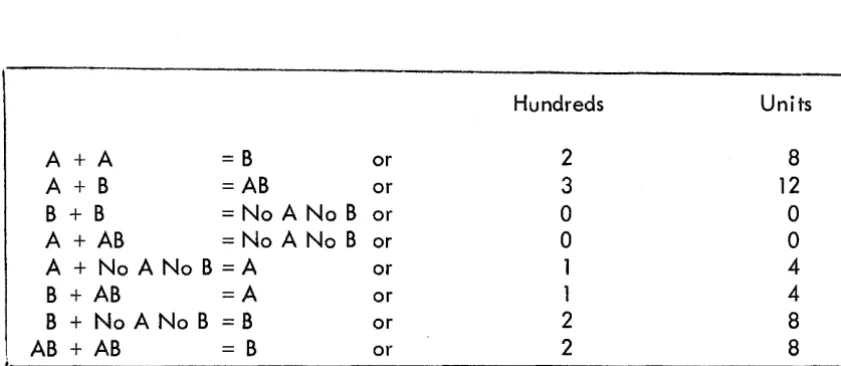
A brief review of the makeup of the 1401 core storage address codes is desir-able. The 1401 has a three character address. The numeric values of the three characters range from 000 to 999, thereby specifying one out of 1000 locations. The zone bits over the hundreds' and units' positions of the address indicate by mod-uJus 16 arithmetic (figure 1) which of the sixteen groups of 1000 core locations is designated. The zone in the units position of the address specifies which quadrant of 4000 storage locations is referenced, while the zone in the hundreds position determines which group of 1000 locations is referenced wthin a quadrant.
The binary character to be converted is used to formulate a unique core address, which then locates the proper two digit octal representation in a table
(figure 2). Ideally th is character is placed directly in the hundreds position of an index register used to access the tabl e . This wi II not work in all cases, however, since only forty of the sixty-four possible character configurations are val id storage address codes. To clarify this procedure let us first examine how this technique words for the forty val id address codes.
The table of two digit octal constants for these forty character configurations is distributed from locations 4087 to 7987, separated by increments of 100 locations (figure 2) e For the conversion, index register 1 is preset to a value of 087 (step 1)
and the character to be converted is moved into the hundreds position of the index register (s·tep 2), thereby replacing the zero. The contents of index 1 can now range from a value of 087 to 3987, depending upon the bit configuration of the character to be converted. Now a move instruction is executed as shown (step 3).
Mew 4000
+
Xl, 0210The two digit octal constant, located at the effective address of 4000 plus the con-tents of index 1, is thereby moved to the print area. For example, an input charac-ter with a bit configuration of a "0" causes the following to take place:
Step 1. Step 2. Step 3.
Index 1 = 087
This generates an effective address of 7487 and the octal constant in the table at this address should be 64, as illustrated below.
BIT IDENTITY BIT STATUS BCD ADDRESS VALUE OCTAL VALUE
B ON
}
3A ON 6
8 OFF
}
4 ON 4
2 OFF 4
OFF
Since the zone bits of any character to be converted are always valid, a legitimate storage address code can be identified by determining that the numeric portion of the character is a value from 0 to 9. For each of the twenty-four characters that do not fit this category, the exact bit configuration of the numeric portion of the character must be determined. This is accompl ished through a series of bit tests (see flowchart figure 3) and index register 1 is then preset according to the following table.
BIT POSITIONS
8
4 2 INDEX 1 SETTING BCDOFF OFF OFF OFF 590 BLANK
ON OFF ON ON 090 11
ON ON OFF OFF 190 12
ON ON OFF ON 290 13
ON ON ON OFF 390 14
ON ON ON ON 490 15
Now only the zone of the character to be converted is moved over to the hundreds position of index register 1, and the octal digits can now be set in the print area with the same move instruction used for the val id address code characters.
The flowchart (figure 3) explains the detailed instruction logic and the core storage layout (figure 2) shows the table distribution and values for the first 1000
locations.
This illustration used a binary to octal transformation, but there are other conversion requirements which fit this table look-up approach. A few examples are I isted here.
1. Five or eight channel paper tape conversion to BCD characters. 2. Fixed point binary numbers to decimal integers.
3. Conversion of column binary cards to row binary cards.
THE RANDOMIZING AND CHAINING APPROACH
This approach is an adaptation of the RAMAC method for randomizing and chaining disk records. To illustrate this technique, we will assume that the octal words assembled from the binary tape in the previous example are actually 7094 program instructions. It is therefore desirable for the programmers that the appro-priate 7094 mnemonic language codes are printed with the octal words to facHitate program debugging. A 1401 routine is needed to look up the mnemonic designation for the octal operation code.
The basic 7094 operation code consists of the second, third and fourth octal digits of each word. The first digit of each word is called the prefix, and with the exception of six instructions, the prefix will always be either 0 or 4, commonly referred to as positive or negative. As there are no eights or nines in the octal system, the other three digits can range in value from 000 to 777. Many of these numbers do not constitute legitimate 7094 operation codes. Some combinations are val id only if the prefix is positive, and some only if the prefix is negative, while some other operation codes represent instructions in both the positive and negative form. Certain operation codes are more complex and require that other digits be decoded for proper instruction execution. These are not relevant to this discussion and they wi II be disregarded. They can be treated by exception or as variations to this table look up approach.
The table of mnemonic language codes is again located in the upper 4000 positions of storage (figure 2). To accomplish the table look up, the three digit operation code is randomized by multiplying by a factor of 5. The answer is a minimum of 0000 and a maximum of 3885. This number must be converted to a three character core storage address. By examining the thousands' position of the result, index register 1 is set according to the following table.
THOUSANDS" POSITION INDEX 1 NUMERIC EQUIVALENT
o
oof.
4000fO*
50002
OO~
60003
0
0*
7000The three low order positions of the multiply field are then added to the contents of index 1, thus providing a three character 140'1 core storage address equivalent to 4000, plus the result of the multiplication. This address will be the test position for each operation code. If there is no wordmark associated with the
test position address, the operation code is not val id. The 7094 word is therefore a data word and a mnemonic interpretation is not printed. When a wordmark is present at the test location, the octal code represents a legitimate instruction. Further tests on this position establ ish the condition for which this operation code is val id, as
indicated below:
1. A "B" bit (-) indicates the operation code is valid only if the prefix is negative.
2. Both" A" and" B" bits (+) indica'te the operation code is val id only if the prefix is positive.
3. A "1" bit indicates the operation code is val id for both a positive and a negative prefix.
If only one form of the operation code is val id, then the mnemonic equivalent is located in the four core locations preceding the test address. Therefore, if the prefix satisfies the condition, the mnemonic constant can be moved to the appropriate position
in the print area. The word is again assumed to be a data word if the prefix is not of the same sign as the test position stipulates.
When both forms of the operation code are val id, a chain core storage address is provided in the three storage positions preceding the test address. This chain address is moved into index register 1. For the positive prefix, the mnemonic language code is located in the four positions preceding the chain address, while for the negative opercJtion code, the mnemonic equivalent is found in the four positions following the chain address. A simple test on the prefix of the 7094 word will therefore determine which mnemonic (using index 1) is to be moved to the print area.
It is interesting to note the distribution pattern of the mnemonics in the table area (figure 2). Two fields of ten characters each, from position 36 to 45 and from positions 86 to 95 in every hundred core locations, remain entirely free. In addition, the clreas from 396 to 485 and from 896 to 985 remain free for every thousand core locations. This, of course, is the result of multiplying an octal number (containing no eiights and nines) by a factor of five. It makes it possible to combine the binary to octal conversion table of the previous discussion with the mnemonic language table.
THE MULTIPASS TABLE LOOK-UP
The illustration used to explain this multipass technique for tables exceeding core storage capacity is an editing program pertaining to airline passenger statistics. The program has to verify the accuracy of the input information and provide a record of the errors found. The tape records to be ed ited are summaries of airl ine passenger routings. The information is in coded form as illustrated by the following example:
LGA FA CHI PJ LAX
These passengers flew from New York (LGA) to Chicago (CHI) by Ficticious Airlines (FA) and from Chicago to Los Angeles (LAX) by Phantom Jetlines (PJ). The editing checks required are as follows:
1. Do the abbreviations represent legitimate city and carrier codes? 2. Do these airlines run a regularly scheduled flight for the cities
reported in the routing?
The table used to edit the tape records frequently has to be revised as new airports are opened and flight itineraries are altered. This makes it practical lro keep the table information in punched cards, so the table can be easily updated to reflect the changes. The table cards consist of the city code, followed by the
identifying codes of the airl ines providing service to that city. The cards are grouped together al phabetically by the first letter of the city code to decrease processing time in the edit phase. The entire table cannot fit into core storage at one time, yet a tape data record may contain any of the city codes. For this reason, the data tape must be passed once for each section of the table loaded.
The program consists of a loading routine and an edit routine. The loading routine loads each city as a table segment of variable length. The length of each segment is determined by the number of airl ines servicing the city. The total number of characters occupied by each table segment is inserted in the first three characters of the segment. This is analogous to the usual procedure for formatting variable
lengths tape records. The segment length is followed by the city code, behind which are placed the applicable airline codes.
The loading routine has several other important functions. It must initial ize a sequence 'of twenty-six constants which represent the starting core locations for each group of city codes with the same first letter. These constants allow the edit routine to I imit its search for a matching city code by examining only that section of the table pertaining to cities with the same initial code letter. The twenty-six constants each have a test character associated with it. This test character is coded by the loading routine. It will indicate to the edit routine whether that group of table cards has been completely loaded in the table, is partially loaded in the table, or is not in core for this edit pass.
The loading routine must accumulate a count of the table area loaded, and compare this to a constant designating the total amount of core storage avai lable for the table. When the table area is filled, or all the cards are processed, the loading routine passes control to the edit routine.
The edit routine accesses a city code in the tape record and looks it up in the table. It uses the first letter of the city code to determine which of the twenty-six constants, set up by the load program, is to be used. The test character is examined first to see if the city code group has been loaded. If this group is not in core, the edit routine proceeds to the next city code in the tape record. If the group has been loaded, the edit routine, using the appropriate constant, initializes the table index register to the starting core location for that city code group. After a city in the tabl:e has been checked for a match, the length of that table segment is added to the table index register. This provides access to the next city code in the table. When a match is found, thE~ edit routine checks the carrier or carriers designated in the rou1ring as servicing the city against the carriers listed in the table segment. The length of the segment, as specified in the first three characters, allows the edit routine to determine when all the airl ine codes have been examined. If no match is found for a city code, the test character for that group of cities must be checked to determine if the group was only partially loaded in the table. If this is the case, no error or completion indication is set.
The edit routine reads and writes the data tape records in the load mode for each pass of the tape. This enables it to indicate with wordmarks the codes already edited and 'the errors found. When a city code has passed the edit successfully, a wordmark is set under the high order position of the three character city abbreviation
in the tape record. Errors are indicated in the following manner:
1. A city code not matched in the table has a wordmark set in each character of the code in the tape record.
2. An airline represented in the routing as servicing a city for which it is not listed in the table, causes wordmarks to be set in all posi-tions of the airline and city code in the tape record.
Hundreds Units
A+A =B or 2 8
A + B = AB or 3 12
B + B = No A No B or 0 0
A + AB = No A No B or 0 0
A + No A No B = A or 1 4
B + AB =A or 1 4
B + No A No B = B or 2 8
AB + AB = B or 2 8
figure 1 - Modulus 16 Arithmetic
Reference: IBM 1401 Data Processing System - Reference Manual A24-1403-5
[image:13.615.101.522.148.331.2]IBM
v '=' woR.])MflRK
\NHRNATIONAl f)USINESS MA( HINf~, \ ORPOfUdICH'l
IBM 1401 DATA PROCESSING SYSTEM
STORAGE LAYOUT
o == #0 vtlOR:J>MIMI< IN-LOWe])
APPLICATION _ _ _ _ _ _ _ _ _ _ ,''-''N-<---'-TLLH.odCLr---'-p-'c~_''~_LJ~ ~ L!L ____ _
l
I
" , / 1 0 0 - 4''17
I
I
I
i
lr-
--_._- --- .. - - --_.- - -.. --- - T---- " - - - -..I ~ J
SYMBOLIC
DATA
I WORD MARK I" ,v, ,II ,t/ t I , ,0 ,II ,J 0 1/ ,~ 'II ,,J tI, Iv. ,t,/_ 81 ,J, ,J ,II, ,,/ ,,/ ,lfiti', ..JObl ~~
D"
,01..-, 1.1I SYMBOLIC II rRC t;"
II
DATA )SA
lRIII,q t TI(J I tr---'1L .1. PM -.i :Ds4 fIrJ TReE. ITRCF rReG iTRfl1 IIR ;PSfi I r£FA IrE~lJ RFT J)S~ I J)SII SI~ I J)sll RNT....1 .JJ.JK :Dstil 1la.2 lL5
I LOCATION 10 '5 10 15 ~ 25 '~ 3 4( 45 5 55 6 6 7 7 85 ~
; WORD MARK 1"1... ,oj ,ii, "'ttl, ..I hi ,;
, SYMBOLIC "TereN
I
I 1)sA J)SIJ J)SA ~Sll 1>$.4 ~_4 3>S~
DATA II rc.aJ, I 720e J naJJl rCf>£ I IcoF I /(0& I --rcDJlJlr£F~ J£rJ> r£~E IrEF.f" r£~6. ITE"£.ll r...SA ~
I LOCA nON 0 5 10 15 ~ 25 3 3 4( 45 5 55 '6 6 '"
I WORD MARK i l l " ,oJ ,II ,J ,.I ,0/ -t/ ,v ,v ,,J .. I , I , J, Ji.l lv, 1.1, 1I ,J, ,c. rI ,t " ,e .t, ~
I SYMBOLIC
WORD MARK I
I SYMBOLIC
, , '5' ,
"TIL"
i I
10 I i 160' I I i [65[
"rrR" "RFT" II R NT" I'R IR"
I~
7 8
FORM X24 6438 2 t
PRINTED IN USA
95
95
IBM
DIAGRAMMING AND CHARTING WORKSHEETApplication _ _ _ _ _ _ _ _ _ _ _ _ _ _ _ _ _ _ _ _ _ _ _ _ _ _ _
Procedure _ _ _ _ _ _ _ _ _ _ _ _ _ _ _ _ _ _ _ _ _ _ _ _ _ _ _ _
[\1 i05 ,06
yes
I~
! ?
-'2'
t
"Tj0 2A
c:
r,
C<, '-~ .,
rJ
8
c~
~.
PAGe. IS"
Date
Drawn By
IJ
For", X22-64 I 3-? Prrnted Irl U.S.A.
Page _ _ _ of _ _
18 I"
_,-,---t --,
Mt ... ' ~CJ{J{i~X 1.11
c;t,o I
"--_~.,(Jj,;; THE. <,'Glit.tl
C"_D6 Ie THE I