DETECTION OF FAULTS IN INDUCTION MOTOR BY USING DWT
Snehal O. Gulhane1, M. R. Salodkar2 1
G.H.Raisoni Csollege of Engineering, Amravati, India
2
Assistant Professor at Electrical engineering department, G. H. Raisoni College of engineering, Amravati, India.
ABSTRACT
Induction motors play a very important role in all the sectors. In industries, these motors have to run continuously in order to drive the load without any breakdown. Due to the continuous use, these motors are prone to the development of faults. Early detection of faults in the motors can help to avoid major failures. Hence it is required to monitor the motors continuously in order to avoid major failures and breakdowns. This paper presents the detection of the motor faults such as overvoltage, phase reversal, single phasing etc. in squirrel cage induction motors.
Keywords:-Induction motor, Types of Faults, Condition Monitoring, Wavelet Transform.
Introduction
The polyphase induction motor is having low cost, simple and rugged construction, absence of commutator, good operating characteristics etc. The distinguishing
feature of such a motor is that it is singly excited machine, although such machines are equipped with field and armature windings. Due to such advantages, these motors are widely used.
Induction motor is also called as asynchronous motor which is made up of two main parts i.e. stator and rotor. As the name suggests, stator is stationary part and the rotor is rotating part. The energy is getting transferred from the stator to the rotor due to the electromagnetic induction principle and hence the motor is called as induction motor. According to construction, there are two types of motors:-
1) Squirrel cage induction motor 2) Slip ring induction motor
The conducting bars are used in squirrel cage induction motors in order to carry the current. These bars are short circuited by end rings and due to which external resistance cannot be added. In case of slip ring induction motor, the polyphase winding is used. The terminals of thispolyphase windings are connected to
GE-International Journal of Engineering Research
Vol. 4, Issue 10, October 2016 IF- 4.721 ISSN(O):(2321-1717), ISSN(P):(2394-420X)
© Associated Asia Research Foundation (AARF) Publication
slip rings. An external resistance can be added into the circuit with the help of slip rings. Squirrel cage induction motors are mostly preferred as it is having the advantages like rugged construction, cheap in cost, having no commutator, suitable for high speed etc.
Though the induction motor is more reliable but the occurrences of faults in it cannot be avoided. Early detection of abnormalities in the motors will help to avoid major failures. Thus, in order to avoid the occurrences of such failures, it is required to diagnose the fault as early as possible. If these faults are not diagnosed on time, it may affect the motor’s performance.
Various Types of Faults
Following are the various types faults which may occur in the three phase induction motor:
1) Mechanical faults 2) Electrical faults
1.Mechanical faults
Following are the mechanical faults which occur in the three phase induction motor:-
a) Air Gap Eccentricity:- In case of healthy motor, the centre of rotation will be same for stator and rotor. But when this centre of rotation is different, we said there is air gap eccentricity. Due to misalignment of stator and rotor, unbalanced radial forces are acted and it damages the stator and rotor. Again, there is production of noise and vibrations.
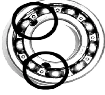
b) Bearing Faults:- Bearings are used in order to reduce the frictional losses. Continuous use of bearings creates stress on them which results in rough running of
[image:2.595.326.508.86.251.2]the bearing. High temperature at bearings is also one of the reason for bearing faults.
Fig. a: Bearing Fault
c) Broken Rotor Bars:- This fault is mainly related with the squirrel cage induction motor. If one of the bars of rotor gets break, there occurs asymmetry in the rotor cage which results in the asymmetrical distribution of rotor currents. And this ultimately results into multiple bar fractures.
2.Electrical Faults
Following are the electrical faults which occur in the three phase induction motor:-
Fig. b: Under Voltage
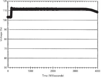
b) Over voltages:- Over voltages are R.M.S. voltage variations that exceeds 110% of the nominal voltage. Several types of initiating events causes the overvoltage. Overvoltage in induction motor will cause reactive current to increase because of which there is production of heat due to eddy current.
Fig. c: Over Voltage
c) Single phasing:- Single phasing is a condition in three phase induction motor where one of the phase out of three phases are cut off. Because of single phasing, there is production of noise and vibrations.
d) Phase reversal:- The three phases of induction motor, suppose R, Y, B, should be properly connected to the load’s phases. If any of the phases gets misplaced during the connection then, there is occurrence of phase reversal. Due to phase reversal, the motor may start to run in opposite direction because of which wear and tear may occur.
Importance of Condition Monitoring As we seen earlier, there are various effects of faults on the performance of induction motor. So condition monitoring has a special importance in the business environment due to following reasons:
a) To reduce the cost of maintenance. b) To predict the equipment failure. c) To improve equipment and
component reliability.
d) To optimize the equipment performance.
e) To improve the accuracy in failure prediction.
In this paper, Wavelet Transform technique is used as a condition monitoring technique. Lets see its description in the upcoming chapter.
Wavelet Transform
Mathematical transformations are applied to signals to obtain further information from that signal that is not readily available in the raw signal. The number of transformations is available which can be applied, among which the wavelet transform is most popular.
[image:3.595.80.255.343.479.2]better in time. On the contrary, low frequency components can be located better in frequency compared to high frequency components.
The frequency and time information of a signal at some certain point in the time frequency plane cannot be known i.e. we cannot know, what frequency components exists at any given time instead, we can investigate what frequency components exists at any given interval of time. This is a problem of resolution and it is the main reason why researchers have switched to wavelet transform.
The advantages of using wavelet transform for diagnosing the induction motor faults are as follows:
1) The main advantage of Wavelet Transform is that, it can work both in time and frequency domain. 2) Wavelet transform is
computationally very fast.
3) By using wavelet transform, it is possible to decompose a signal into component wavelets.
Need of Wavelet Transform
The discretized continuous wavelet transform enables the computation of the continuous wavelet transform by computers. But it is not a true discrete transform. As a matter of fact, the wavelet series is simply a sampled version of the Continuous Wavelet Transform and the information it provides is highly redundant as far as the reconstruction of the signal is concerned. This redundancy requires a significant amount of time and resources. While, the discrete wavelet transform (DWT) provides sufficient information both for analysis and synthesis of the
original signal, with a significant reduction in the computation time.
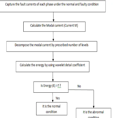
[image:4.595.329.518.409.607.2]Detection of Faults of Induction Motor Here, the faults are detected depending upon the comparative study of energy bar graph. The energy bar graph can be drawn by using the algorithm given below. The program can be developed in MATLAB using the models in MATLAB simulink. One can capture the phase currents for all the three phases. The capturing of individual phase currents requires more time. In order to reduce the time duration of current capturing, we are calculating the modal current and this modal current is then applied to the motor. Daubechies db4 is used to decompose the modal current. And then calculate the energy by using wavelet detail coefficients. These coefficients are calculated for normal and faulty condition.
Fig. d: Algorithm for plotting energy bar graph
greater than 7 and accordingly one can detect the fault. That is whether the motor is operating normally or in faulty condition.
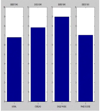
Fig. e: Energy Bar Graph
Conclusion
In this paper, the method of fault detection of induction motor presented. We come to know that Wavelet transform method is most suitable for the detection as it can diagnose the fault in transient condition and it has more advantages than any other method. Here, we performed comparative study of the energy as Energy bar graph is one of the easiest way to detect the fault in the induction motor.
References
[1] AhceneBouzida, Omar Touhami, RachidIbtiouen, Adel Belouchrani, Maurice Fadel and A. Rezzoug, “Fault Diagnosis in Industrial Induction Machines Through Discrete Wavelet Transform”, IEEE transaction on industrial electronics, vol. 58, No. 9, September 2011.
[2] HocineBendjama, Salah Bouhouche and Mohamed SeghirBoucherit, “Application of Wavelet Transform for Fault Diagnosis in Rotating Machinery”, International
Journal of Machine Learning and Computing, vol. 2, No. 1, February 2012.
[3] R. Satish, R. Devarajan, P. Ganga, “ Analysing and Detection of Rotor Faults in Squirrel Cage Induction Motor Drives Using MATLAB”, International Journal of Advanced Research in Electrical, Electronics and Instrumentation Engineering, vol. 4, issue 6, june 2015.
[4] Mrs. Anjali U. Jawadekar, Gajanan Dhole, SudhirParaskar, “Novel Wavelet ANN technique to classify Interturn Fault in Three Phase Induction Motor”, International Journal of Advancements in Technology, vol.2, No. 2 (April 2011).
[5] Chaitali S. Kalaskar, Vitthal J. Gond, “Motor Current Signature Analysis to detect the faults in Induction Motor”, International Journal of Engineering Research and Application, ISSN: 2248-9622, vol.4, Issue 6 (version 1), June 2014, pp. 58-61.
[6] Dr.Shashi Raj Kapoor, “Commonly Occurring Faults in Three Phase Induction Motor – Causes, Effects and Detection – A Review”, Journal of Information, Knowledge and Research in Electrical Engineering, ISSN : 0975-6736, Nov 12 to Oct 13,Vol. 2, Issue 2.