
Fingerprint Matching using Neighbourhood
Distinctiveness
Iwasokun Gabriel
Babatunde
Federal University of Technology, PMB 704, Akure, Ondo State,
Nigeria,
Akinyokun Oluwole Charles
Federal University of Technology, PMB 704, Akure, Ondo State,Nigeria
Angaye Cleopas Officer
National Information TechnologyDevelopment Agency, Abuja, Nigeria
ABSTRACT
The issue of identity management has continued to pose serious security challenge to different organizations. To cub this challenge, emphasis is now been shifted from what you know or have to what you are leading to increasing use of fingerprint, iris voice, face image and other physical biometrics for human verification and identification. Among these, fingerprint has proved most reliable and dependable. This has precipitated the emergence of a good number of Automated Fingerprint Identification Systems (AFIS) with different forms of matching algorithms. This paper presents the formulation and implementation of a minutiae based fingerprint pattern matching algorithm. The algorithm relies on the spatial characteristics defined over the 11 x 11 neighbourhood of the fingerprints core points to determine the matching scores, which exhibit the degree of resemblance for any two images. Results obtained from the implementation of the proposed algorithm show its good performance. Comparative analysis of the obtained FNMR, FMR and computation time values with values obtained from some other research works shows a superior performance of the proposed system.
Keyword: Fingerprint, Pattern Matching, Core Point, Minutiae, FNMR, FMR
1.
INTRODUCTION
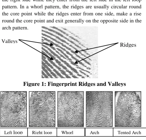
The issue of identity management of individuals, organizations and other public and private institutions poses a great challenge to government worldwide today. Biometric identification has featured prominently for individuals with fingerprint emerging as the dominant one. The dominance of fingerprint has been buttressed by the continuous emergence of different forms of Automated Fingerprint Identification Systems (AFIS). Fingerprints are the results of minute ridges and valleys in the fingers of every person. The ridges are the dark and raised portions while the valleys are the white and lowered portions as shown in Figure 1. The ridges do not change at any time, from birth until death. No matter what happens, they reappear within a short period. In most cases, they appear in any of the five major patterns; namely left loop, right loop, whorl, arch and tented arch as shown in Figure 2 [1-6].
In the loop pattern, the ridges enter from either side, re-curve round the core point and pass out (or tend to pass out) the same side they entered. In the right loop pattern, the ridges enter from
the right side while they enter from the left side in the left loop pattern. In a whorl pattern, the ridges are usually circular round the core point while the ridges enter from one side, make a rise round the core point and exit generally on the opposite side in the arch pattern.
A fingerprint may be described as captured or latent print [7]. A captured print is obtained for different purposes. When a person is arrested in connection with a crime, as part of the booking process, the police or other security agent rolled the arrestee’s fingertip in ink and then impressed it on a card. The card is subsequently stored in libraries (of such cards) maintained by local, state or national agencies. Captured prints may also be obtained using modern day finger scan system [8-9]. The dawning of electronically scanning fingers to obtain fingerprint images and intelligent computer processes and algorithms that enhance, enroll and match prints to an extremely high accuracy level has provided an efficient means of satisfying the need for a full automation of fingerprint identification process. The basic components of a fully automated finger-scan system shown in Figure 3 comprise of components for image acquisition, processing and template generation, matching and storage. These components can be located within a single peripheral or standalone device, or may be spread among a peripheral device, a local PC, and a central server [8].
Latent print in contrast, is typically produced at a crime scene and is usually not readily visible. It occurs when the natural secretions of the skin are deposited on a surface through fingertip contact. The best way to render latent fingerprints visible for photographing is complex and depends, for example, Ridges Valleys
[image:1.595.305.554.213.452.2]Figure 1: Fingerprint Ridges and Valleys
Figure 2: Basic types of fingerprint pattern Left loop Right loop
loop
on the type of surface involved. A ‘developer’, usually a powder or chemical reagent, is mostly used for producing a high degree of visual contrast between the ridge patterns and the surface on which the latent fingerprint was left [7, 10].
A wide margin exists between the uses of fingerprint for identification over other biometrics. The result of the survey conducted by the International Biometric Group (IBG) in 2004 on the use of biometrics for identification shows that fingerprint with 48% of the total use, enjoys high superiority over other biometrics such as hand, iris, voice, signature and face as shown in Figure 4 [11].
The uniqueness of the pattern of friction ridges on a finger makes it immutable and therefore provides a strong mark of identity. Notably, even identical twins are differentiable using their fingerprints [5]. Areas where fingerprints are frequently used for identification include access to military installations, control room and other high profile offices or stores. Others are bank transactions, voting, visa applications, Subscribers Identification Module (SIM) card and examinations [12-13]. Fingerprint is also used for verification where an input (reference) fingerprint is compared with a previously enrolled (template) fingerprint to know if the two are from the same finger or not (1:1 match) [9]. The major reasons for the wide use of fingerprints for identification and verification include:
a. Availability for all individuals irrespective of race, gender or age
b. Availability of easy, smooth operational and cheap fingerprint capturing devices
c. Stability in pattern or form over time.
d. Fingerprint is distinct and highly unique from individual to individual
Most of the existing fingerprint pattern recognition and matching systems rely on the characteristics exhibited by the
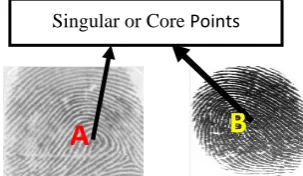
fingerprints core and minutiae points. The core point is the point of maximum turning and is the point at which the gradient is zero. The core points A and B shown in Figure 5 are the points of maximum turning of the ridge structures in the two images. They are also the points where the directional fields experience total changes. The minutiae are the commonest points that uniquely describe a fingerprint image.
Mostly found and important ones are the bifurcations and ridge endings. In Figure 6, circles and squares represent the extracted bifurcations and ridge endings respectively for the thinned image. Other less encountered minutiae points are shown in Figure 7. Sections 2, and 3 of this paper discuss the general terms in pattern matching and the proposed fingerprint pattern matching system respectively while Sections 4, 5 and 6 present the implementation environment, experimental study and the conclusion respectively.
2. PATTERN MATCHING
Fingerprints matching evolved out of pattern matching. Pattern matching involves identifying a complex arrangement of sensory stimuli [14]. Apart from fingerprint, it may also involve character, facial image, signature and so on [15]. Feature based pattern matching is the process of matching the basic features of any of the biometrics of an individual against the features of the recorded template of the same biometric to verify identity [12]. For instance, feature based pattern matching of fingerprint is concerned with the recognition and matching of a set of primitive features of latent fingerprint with enrolled fingerprints in a certified database. It is majorly concerned with finding the pair-wise correspondence between features in the reference and template images using the global and the basic features [16]. Global features include the basic ridge patterns, feature type, Platen
Module
[image:2.595.59.253.126.388.2]Peripheral Figure 3: Components of a finger-scan system.
[image:2.595.56.254.129.232.2]Figure 4: Comparative survey of fingerprint with other biometrics
Figure 5: Fingerprint images and their core points
O A
Singular or Core Points
B
[image:2.595.343.495.161.249.2]A
Figure 7: Major features of the fingerprint
Figure 6: Fingerprint Bifurcation and Endpoints Ridge ending
[image:2.595.317.535.382.559.2]orientation, spatial frequency, curvature and position. It also includes the core and delta areas, type lines and ridge counts. The local features, also known as minutiae points, are the tiny, unique characteristics of fingerprint ridges that are used for positive identification. They contain the information that only exist in the local area and are invariant with respect to global transformation. A fingerprint feature based pattern matching system is considered as widely acceptable if it is reasonably insensitive to distortion and noise and guaranteed the detection of a core in type of fingerprints like the arch that lack a discontinuous of its directional field. In [17], a feature based algorithm for pattern recognition of fingerprint is proposed. The features that were used are the core and minutiae of the fingerprints. These set of points were used because they are the commonest and the same form irrespective of the ridge pattern. Other reasons include easy identification and variation in the type of pattern.
In [27], a feature-based partial fingerprint recognition system with emphasis on the localized features of the partial fingerprints is proposed. A partial fingerprint results in the incomplete image of the finger, which may be as a result of small sensing area (platen) of the fingerprint sensor, improper placement of the fingertip on the platen or Injury on the fingertip [5, 18]. The work provides platform for addressing problems emanated from the miniaturization of the fingerprint sensors that has small sensing areas and capture only a part of the fingertip as well as reducing or eliminating problems associated with inequality in the size of the sensed image and the stored template for effective fingerprint matching. With low or poor quality fingerprint, there is prolonged and delayed task of minutiae detection and extraction. The authors in [19-21] proffered solution to the problems of poor and false results often encountered when detecting basic features from bad (noisy and poor quality) fingerprint by using robust minutiae detection algorithms. The authors in [22] propose a new fast automatic technique for fingerprints recognition and identification. The technique depends greatly on image segmentation in which a fingerprint image is partitioned into two regions; namely the foreground that contains the relevant biometric sample and the background that contains noises. In [23], a pattern recognition and matching algorithm of fingerprint based on core point is proposed. The work provides a fingerprint pattern recognition and matching algorithms that is suitable for online applications.
3. THE PROPOSED PATTERN
MATCHING SYSTEM
The conceptualization of the proposed system is presented in Figure 8. The first subsystem is the fingerprint data-mining engine, which has fingerprint enhancement, minutiae extraction, database of the extracted minutiae and pattern matching as components. The fingerprint data-mining engine is responsible for the enhancement, extraction, storage and processing of features to obtain summarized data which could assist in taking notable decisions on the degree of resemblance of fingerprints. At the fingerprint image enhancement sub-module, the removal of noise and artifacts from the images using the multi-stage fingerprint image enhancement algorithms implemented in [21,
24-26] takes place while the minutiae extraction sub-module extracted minutiae from the enhanced image using the algorithm proposed in [21,26]. A database of the extracted minutiae, which serves as repository of the extracted minutiae is formulated at the minutiae database sub-module. The database assumed a relational database model for defining the relationships among the minutiae from different fingerprints. This ensures effective and dynamic minutiae storage pattern for open-ended and unrestricted growth of the database. The database stored tables of related entities which include fingerprint unique identification number, type, minutia x and y coordinate points, orientation, type of minutia among others.
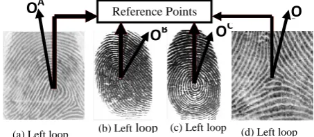
The second sub-system is the pattern-matching module which uses an algorithm that depends on the distances between the image reference and the minutiae points. The algorithm is based on the observation that each minutia has a given number of neighbours and its relative distance to the reference point does not change irrespective of the orientation for a specific size. The reference point may be a core or delta point. The core points OA, OB and OC shown in Figure 9(a), 9(b) and 9(c) respectively are the points of maximum orientations of the ridge structures. They are also the points where the directional field becomes discontinuous [16]. The delta point is the point where the ridge points in three directions. The in-between angles of the three directional ridges are approximately 1200 as shown on point OD of Figure 9(d).
The algorithm used in the proposed system is premised on the assumption that straight lines connect each feature point to other feature points in the image. Figure 10 illustrates typical interconnection lines between a minutia point O and nine (9) other minutiae points A, B, C, D, E, F, G, H and I in an image. The lines are in various directions with lengths proportionate to the distances apart between point O and the minutiae points.
[image:3.595.305.563.222.326.2]The algorithm is in the following phases:
Figure 9: Fingerprint images and their reference points
O
AO
D
O
CReference Points
O A
O
B(a) Left loop (b) Left loop (c) Leftloop (d) Left loop Figure 8: Conceptual diagram of the framework for the proposed hybrid system
Fingerprint Minutiae Extraction
Fingerprint Data Mining Engine
Fingerprint Enhancement
IRS: Image Ridge Segmentation IRN: Image Ridge Normalization RBN: Ridge Binarization RTH: Ridge Thinning; PM: Pattern Matching
FNMR: False Non-Match Rate
CF: Cognitive Filter
EF: Emotional Filter
IRS
IRN
Filtering
RBN/TRH
Database of Extracted Minutiae
[image:3.595.316.543.533.632.2]a. Obtain the core point using the following steps [27]. Firstly, blocks of size S x S are formed on the normalized
fingerprint image.
For each pixel, (p,q) in each block, the gradients (p,q) and (p,q) were computed as the gradient magnitudes in the x and y directions, respectively. (p,q) was computed using the horizontal Sobel operator while (p,q) was computed using the vertical Sobel operator [21].
The local orientation for each block centered at pixel I(i,j) is then computed from:
, , , and Ɵ(i, j) is
the least square estimate of the local orientation of the block centered at pixel (i, j).
The orientation image is then converted into a continuous vector field defined by:
and are the x and y components of the vector field, respectively.
Gaussian smoothing is then performed on the vector field as follows:
(8)
G is a Gaussian low-pass filter of size .
The orientation field O of the block centered at pixel (i,j) is finally smoothed using the equation:
The direction of gravity of progressive blocks (non-overlapping sub block) for each S x S block is determined by using the equations [28]:
Fine tune the orientation field as follows [28]:
If Q(i,j) ≠ 0 then λ= 0.5tan-1(Q/P)
else λ =π/2 if λ < 0 then if P < 0 then
λ= λ +π/2
else: λ= λ +π else if P < 0 then:
λ = π/2
The value λ is calculated as the orientation value of the image.
The blocks with slope values transiting from 0 to pi/2 are located and a path is traced down until a slope that deviates from this range is encountered and that block is marked.
The block that has the highest number of marks will compute the slope in negative y direction and its x and y position will be the core-point.
b. The equations of the straight lines connecting all the feature points in the 11 x 11 neighbourhood of the core point of the image are calculated. Given that points
) and ) shown in Figure 11 are two feature points located in this neighbourhood for an image, the equation of the straight line P1P2 is given by:
(12)
is the gradient of line P1P2 . is defined by:
c. The point of interception of any two straight lines forms a junction point as shown in Figure 12.
The locations of all the junction points in the 11 x 11 neighbourhood of the core point are obtained by solving all possible pair of equations of straight lines. Given that straight lines AB shown in Figure 12 is defined by the equation:
x + y =
and the straight line CD is defined by the equation: x + y =
The junction point J(e,f) is obtained from:
)
)
Figure 11: Presumed feature points
Figure 12: Junction point of straight line formed by feature points
C
D
J(e,f) x + y =
= x + y =
A
B
O
A
B
C
D
E
F
yH
I
G
d. The distance, i between the i th
junction point Ji(ei,fi) and the image core point M( ) is obtained from:
e. For the query and reference images, the degree of closeness, is obtained from:
n is the smaller of the respective number of junction points in the query and reference image, P(i) and I(i) represent the distance between the ith junction point and the core point for the query and reference image respectively.
The cross-correlation coefficient value, C is then computed as the pattern matching score for any two images by using the formula: From this formula, the dissimilar value will be = 0 for exact or same images and, consequently, the cross-correlation will be C = 100.
4.
OPERATIONAL ENVIRONMENT
The major goal is to design and implement a minutiae-based fingerprint pattern matching system based on the spatial characteristics of the minutiae points. For the attainment of this objective, the operational environment for the proposed system is characterized by Microsoft Windows Vista on a Pentium 4 – 2.10 GHz processor with 1.00GB of RAM. Matrix Laboratory (Matlab) Version 7.2 Windows application development system served as frontend engine and My Server Query Language (MySQL) as backend engine. Matrix laboratory windows application development system is a numerical computing system and a fourth-generation programming language developed by MathWorks Inc (www.mathswork.com). It provides exceptional features for image processing that are rare in other programming languages. These features include matrix representation of images with simplified processing tools, specialized plotting functions and data and availability of readily made codes for implementing common algorithms. It also has optional toolboxes for accessing symbolic computing capabilities and an additional package called Simulink that adds graphical multi-domain simulation and Model-Based Design for dynamic and embedded systems. There is also an embedded database toolbox, which supports the importation and exportation of data from several Open Database Connection (ODBC) compliant database management system including MySQL. Matlab’s ODBCs in Windows platform offers greater compatibility and there are readily made routines for building queries and function calls. MySQL is used because of its high support for web and database applications. It is a very flexible and effective tool for the basic operations that are involved in pattern matching. The basic operations are data creation, storage, modification and retrieval [12]. With MySQL, it is simple to build queries, forms and reports that are suitable for web-based Matlab applications. In addition, a combination of
MySQL and Matlab provides greater support for data abstraction, inheritance, polymorphism and encapsulation in a window platform than in any other platform [21].
5.
EXPERIMENTAL STUDY
Experiments were conducted to analyze the performance of the algorithm under different conditions of images as well as generate the metrics that could serve the basis for the comparison of the obtained results with that of related works. The experiments were carried out using the standard FVC2002 fingerprint database (www.bias.csr.unibo.it/fvc2002/download. asp). The Biometric Systems Laboratory of Bologna, Pattern Recognition and Image Processing Laboratory of Michigan and the Biometric Test Center, San Jose of the United States of America jointly formulated the standard database.
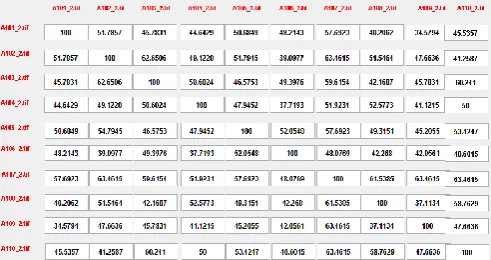
[image:5.595.313.543.252.391.2]The database contains four datasets DB1, DB2, DB3 and DB4 [29-30]. The detail of the datasets is presented in Table 1. The four datasets were of different qualities with each containing 80 fingerprints made up of 5 fingerprints from 16 different fingers. Dataset DB1 and DB2 were acquired using optical fingerprint reader, dataset DB3 was acquired using capacitive fingerprint reader and dataset DB4 was obtained with computer assistance, using the software SFinGE. A subset of ten images from different fingers in Dataset DB4 is shown in Figure 13 with variations in pattern, quality and orientation. The matrix of the obtained pattern matching scores, which represent the extent of match of the ten images is shown in Figure 14. It is shown that a highest matching score of 63.46% exists for image A107_2 and three other images A102_2, A109_2 and A110_2 while the next highest score of 61.53% exists for images A107_2 and A108_2. The least score of 34.57% exists for images A101_2 and A109_2.
Figure 13: Selected images from Dataset DB4
A101_2 A102_2 A103_2 A104_2 A105_2
A106_2 A107_2 A108_2 A109_2 A110_2
[image:5.595.304.550.627.757.2]Table 1: Details of FVC2002 fingerprint database [30]
Database Sensor Type Image size Number Resolution
DB1 Optical Sensor 388 × 374 (142 Kpixels) 100 × 8 500 dpi
DB2 Optical Sensor 296 × 560 (162 Kpixels) 100 × 8 569 dpi
DB3 Capacitive Sensor 300 × 300 (88 Kpixels) 100 × 8 500 dpi
DB4 SFinGe v2.51 288 × 384 (108 Kpixels) 100 × 8 About 500 dpi
TABLE 2: FMR and FNMR values for dataset DB1
Statistics Value (%)
FMR 0
FNMR 15.50
TABLE 3: FMR and FNMR values for dataset DB2
Statistics Value (%)
FMR 0
FNMR 12.50
The closer a score is to 100, the greater the similarity of the images producing it and the greater the possibility they are from the same finger. Similarly, score close to 0 indicates wide difference in the images and increased possibility they are from different fingers.
Three indicators; namely false non-match rate (FNMR), false match rate (FMR) and average matching time (AMT) were measured for the analysis of the performance of the proposed system. These indicators were chosen because they are among the commonest indicators used for measuring the performance of any fingerprint pattern matching systems [9]. FMR is the rate of occurrence of a scenario of two fingerprints from different fingers found to match (matching score exceeding the threshold).
On the other hand, FNMR is the rate of occurrence of a scenario of two fingerprints from same finger failing to match (the matching score falling below the threshold). The FNMR test is accomplished by matching fingerprints from the same finger using the proposed algorithm while FMR test is done through the matching of each fingerprint image of each of the sixteen persons with all other fingerprints from the other persons. The obtained results show that both FNMR and FMR are greatly influenced by the nature and quality of the images. The results obtained for datasets DB1and DB2 are presented in Table 2 and Table 3 respectively. These results reveal that for images obtained using optical fingerprint reader, the proposed algorithm produced an FMR of 0%. This implies that the algorithm is able to identify fingerprint images obtained from different fingers under equal conditions in the two datasets. However, the obtained FNMR values of 15.5% and 12.5% revealed the extent to which the algorithm failed to match substantial number of fingerprint images enrolled from same finger in the two datasets.
A number of factors including variation in enrolment pressure, rotation, translation and contact area [9] are responsible for this. These factors constrained images from the same finger to show unequal quality, contrast and noise levels resulting in irregular feature extractions and different matching scores for different
pairs. The FMR and FNMR results obtained for the dataset DB3 are presented in Table 4. The results show that for the concerned images, the proposed algorithm produced an FMR of 0%. This is also a demonstration of the ability of the algorithm to identify different fingerprint images captured using capacitive fingerprint reader under same conditions. However, the obtained FNMR value of 20.7% revealed the failure rate of the algorithm in its effort to match fingerprint images from same finger. This is also attributed to differences in image qualities. Visual inspection of fingerprints images in dataset DB3 reveals significant breaks and smudged effects on their ridge structures. The enhancement process adversely suffered from these effects as different levels or degrees of artifacts inform of cross over, hole or spike structure [12] were introduced. The presence of artifacts led to the extraction of false minutiae (ridge ending and bifurcation) points whose effects contribute to the high FNMR rate of 20.7%. The highest FNMR value for Dataset DB3 compared to what obtained for the first two datasets establishes its inferiority in term of quality. Dataset DB4’s FMR and FNMR values are presented in Table 5 with FMR of 0% also demonstrates the effectiveness of the propose algorithm in distinguishing fingerprint images obtained from different fingers using computer aids. However, the obtained FNMR value of 14.35% revealed the failure rate of the algorithm when matching images obtained from the same finger.
TABLE 4: FMR and FNMR values for dataset DB3
Statistics Value (%)
FMR 0
FNMR 20.70
TABLE 5: FMR and FNMR values for dataset DB4
Statistics Value (%)
FMR 0
FNMR 14.35
Dataset DB2 has the lowest FNMR average computation time of 0.49 second and 0.59 second for FMR followed by DB1, DB4 and DB3 with average FNMR: FMR computation time of 0.61:0.69, 0.69:0.79 and 0.81:1.07 second respectively. The lowest figure recorded for dataset DB2 is attributed to fewest number of minutiae points in the 11 x 11 neighbourhood of the core points and consequently, smallest number of junction points leading to most reduced computations. Similarly, the highest average computation time recorded for dataset DB3 indicates the availability of highest number of both true and false minutiae points around the 11 x 11 neighbourhood of the core points thereby raising the number of computations. Table 7 presents the FNMR and FMR values for four different algorithms over the same dataset (FVC2002 fingerprint database). Having recorded the lowest FNMR values, the superior performance of the proposed algorithm is established. In addition, it is the only algorithm with an FMR value of zero for all the datasets. No reason is given for the non-availability of FNMR and FMR values for Dataset DB3 and DB4 in [33]. Table 8 presents the obtained FNMR and FMR computations time (measured in seconds) in [32] and the current study. For all the datasets, the proposed algorithm exhibited lower figures, which confirm its superiority in computational speed.
6. CONCLUSION
The implementation of a proposed fingerprint pattern matching algorithm that is suitable for building an Automated Fingerprint Identification System (AFIS) has been presented. Emphasis was on the development of a system that used the spatial characteristics of the fingerprints minutiae and core points to determine the matching scores.
The algorithm used the relative distances between the minutiae points in the 11 x 11 neighbpourhood of the core points because irrespective of orientation, the minutiae points in this region do not change for s specific image size. The essence of confining matching to this region is to reduce the number of computations in the determination of the equations of the interconnection lines and junction points. The results obtained showed the ability of the algorithm to distinguish fingerprints from different sources with average FMR of 0%. However, the ability to match images from same source depends on image qualities. Since a number of images in the used datasets are significantly corrupt due to various effects, the algorithm yielded an average FNMR values of 15.76% with the third dataset mostly affected. The same order of performance was recorded for the FNMR and the average matching time over the datasets. A comparative review of the obtained FNMR, FMR and the computation time values with what obtained for some recently formulated algorithms over the same datasets, revealed best performance for the proposed algorithm. However, the average matching times are still high when compared to results for other algorithms such as the one proposed in [33] which recorded significantly low average matching results. Emphasis will therefore be directed towards the optimization of the proposed algorithm so that the average matching time is considerably reduced. Similarly, efforts will be directed towards ensuring that false minutiae play very minimal or zero role on the matching results.
7. REFERENCES
[1] Eckert W. G. (1996): ‘Introduction to Forensic Science’; New York: Elsevier
[2] FIDIS (2006): ‘Future of Identity in the Information Society’, Elsvier Inc.
[3] Salter D. (2006): ‘Thumbprint – An Emerging Technology’, Engineering Technology, New Mexico State University.
[4] Wayman J., Maltoni D, Jain A. and Maio D. (2005): ‘Biometric Systems’; Springer-Verlag London Limited
[5] Akinyokun O. C. and Adegbeyeni E. O. (2009): ‘Scientific Evaluation of the Process of Scanning and Forensic Analysis of Thumbprints on Ballot Papers’, Proceedings of Academy of Legal, Ethical and Regulatory Issues, Vol. 13, Numbers 1, New Orleans
[6] Yount L. (2007): ‘Forensic Science: From Fibres to Thumbprints’ Chelsea House Publisher.
[7] Michael C. and Imwinkelried E. (2006): ‘A Cautionary Note about Fingerprint Analysis and Reliance on Digital Technology’, Public Defence Backup Center REPOR Volume XXI Number 3 T, pp7-9
TABLE 6: Average Computation time for the four datasets
Dataset Average Matching time (sec)
FNMR FMR
DB1 0.61 0.69
DB2 0.49 0.59
DB3 0.81 1.07
DB4 0.69 0.79
TABLE 7: FMR and FNMR for different algorithms
Ref. [31] Ref. [32] Ref. [33] Current Study
Set FNM R
FMR FNM R
FMR FNM R
FMR FNM R
FMR
[image:7.595.52.286.78.173.2]DB1 52.58 0 89.3 1.7 16.2 0 15.50 0 DB2 50.03 0 88.6 3.7 12.6 0 12.50 0 DB3 73.75 0 91.2 2.4 NA NA 20.70 0 DB4 65.24 .015 81.3 0.9 NA NA 14.58 0
TABLE 8: Matching Time for Different Algorithms
Ref. [32] Current Study
Dataset FNMR FMR FNMR FMR
DB1 2 1.7 0.61 0.69
DB2 4 3.7 0.49 0.59
DB3 2 2.4 0.81 1.07
[image:7.595.299.550.83.152.2]DB4 3 0.9 0.69 0.79
[8] Nanavati S., Thieme M. and Nanavati R. (2002): ‘Biometrics, Identifying Verification in a Networked World’, John Wiley & Sons, Inc., pp15-40
[9] Anil K. J., Jianjiang F and Karthik N. (2010): Fingerprint Matching, IEEE Computer Society, page 36-44
[10] Murray H. N. and Williams G. (2007): ‘Latent Thumb Mark Visualization Using a Scanning Kelvin Probe’; Forensic Science International.
[11] Roberts C. (2005): ‘Biometrics’,(http://www.ccip.govt. nz/newsroom/informoation-notes/ 2005/biometrics.pdf)
[12]Iwasokun G. B (2012): Development of a Hybrid Platform for Pattern Recognition and Matching of Thumbprints. PhD. Thesis, Department of Computer Science, Federal University of Technology, Akure, Nigeria
[13] Henry C L. and Gaensslen R. E. (2001):’Advances in Fingerprint Technology’, CRC Press, Boca Raton, Fla, USA, 2 edition.
[14] Yang S. and Ingrid V (2003): ‘A Secure fingerprint Matching Technique’, WBMA ’03, Nov. 2003, Berkeley, Califonia, USA
[15] Amit Konar (2000): ‘Artificial Intelligence and Soft Computing, Behavioural and Cognitive Modelling of Human Brain’, CRC Press, Inc.
[16] Jiao Yuhua, Yigang ZhangJuncao L and, Xiamu Niu (2008): ‘A Fingerprint Enhancement Algorithm using a Federated Filter’, Information Counter measure Technique Institute, Harbin Institute of Technology
[17] López Alfredo C., Ricardo R. López, Reinaldo Cruz Queeman (2002): ‘Fingerprint Pattern Recognition’, PhD Thesis, Electrical Engineering Department, Polytechnic University.
[18] Tsai-Yang Jea, and Govindaraju Venu (2006): ‘A minutia-based partial fingerprint recognition system’. Pattern Recognition. Vol. 38, 10, pp. 1672-1684.
[19] Espinosa Virginia (2002): ‘A minutiae detection algorithm for fingerprint pattern recognition’, IEEE Systems Magazine, pp 1-7
[20] Chikkerur Sharat, Chaohong Wu, Venu Govindaraju (2004): ‘A systematic approach for feature extraction in fingerprint pattern recognition’, Center for Unified Biometrics and Censors (CUBS), University at Buffalo, NY, USA
[21] Iwasokun G. B., Akinyokun O. C., Alese B. K. & Olabode O. (2012): ‘Fingerprint Image Enhancement: Segmentation to Thinning’, International Journal of Advanced Computer Science and Applications (IJACSA), Indian, Vol. 3, No. 1, 2012
[22] Ali S. M. and Al-Zewary M. S. (1997): ‘A new fast automatic technique for fingerprints recognition and
identification’, Journal of Islamic Academy of Sciences 10:2, 55-60.
[23] Zhang Weiwei, Wang Sen and Wang Yangsheng (2004): ‘Pattern recognition and matching algorithm of fingerprint based on core point’, National Laboratory of Pattern Recognition, Institute of Automation, Chinese Academy of Science, Beijing
[24] Hong Liu, Wau Yifei and Anil Jaiu (2006): ‘Fingerprint image enhancement: Algorithm and performance evaluation’; Pattern Recognition and Image Processing Laboratory, Department of Computer Science, Michigan State University, pp1-30
[25] Raymond Thai (2003): ‘Fingerprint Image Enhancement and Minutiae Extraction’, PhD Thesis Submitted to School of Computer Science and Software Engineering, University of Western Australia, pp21-56.
[26] Iwasokun G. B., Akinyokun O. C., Alese B. K. & Olabode O. (2011): ‘Adaptive and Faster Approach to Fingerprint Minutiae Extraction and Validation’. International Journal of Computer Science and Security, Malaysia, Volume 5 Issue 4, page 414-424.
[27] Iwasokun G. B., Akinyokun O. C. & Olabode O. (2012): ‘A Block Processing Approach to Fingerprint Ridge Orientation Estimation’, Journal of Computer Technology and Application, USA, Volume 3, Pages 401-407.
[28] Navrit K. J. and Amit. K. (2011): ‘A Novel Method for Fingerprint Core Point Detection’, International Journal of Scientific & Engineering Research Volume 2, Issue 4, pages 1-6
[29] Maio D., Maltoni D., Cappelli R. Wayman J. L. and A. K. Jain, "FVC2002: Second Fingerprint Verification Competition," in 16th International Conference on Pattern Recognition, 2002, 2002, pp. 811 - 814.
[30] Li T., Liang C., and Sei-ichiro K.(2009): ‘Fingerprint Matching Using Dual Hilbert Scans’, SITIS, pages 553-559
[31] Perez-Diaz A. J. and Arronte-Lopez I. C. (2010): Fingerprint Matching and Non-Matching Analysis for Different Tolerance Rotation Degrees in Commercial Matching Algorithms, Journal of Applied Research and Technology, Vol. 8 No. 2, page 186-199
[32] Peer P.(2010): ‘Fingerprint-Based Verification System A Research Prototype’, IWSSIP 2010 - 17th International Conference on Systems, Signals and Image Processing, Pages 150-153
![TABLE 8: Matching Time for Different Algorithms Ref. [32] Current Study](https://thumb-us.123doks.com/thumbv2/123dok_us/8083626.783008/7.595.52.286.78.173/table-matching-time-different-algorithms-ref-current-study.webp)
