Workflow and E-Governance: A Case Study in Morocco
ABSTRACT
This paper investigates the relationship between e-governance and workflow systems which are seen as a tool for improving government processes. The study is based on a real case at the ‘Centre Régional d’Investissement’ (CRI) of Marrakech, Morocco. The CRI is a government institution entrusted to coordinate various investment projects at the regional level. This paper presents the implementation of a workflow based platform called Flex-Flow that is intended to implement various administrative procedures and improve the efficiency of administrative services at the CRI.
Keywords
Workflow Systems, e-Governance, Flex-Flow, Corporate Memory, Business Process Reengineering (BPR), Information Control Nets (ICN).
1.
INTRODUCTION
While good governance is considered important, it is also well established that e-governance is the tool that allows achieving it. E-governance refers to the use by government agencies of information technologies such as Wide Area Networks, the Internet, and mobile computing that have the ability to transform relations with citizens, businesses, and other arms of government [1]. It is also clear that software is a key component of the solution. In [2], the author argues that good governance is fundamental and e-governance is instrumental, and no e-governance tool can be successful without focusing attention to process reforms for good governance. The positive impact of e-governance on governance is a reality as acknowledged by many implementations in real life [3] [4]. Good governance dictates the design and shape of e-tools for improving governance outcomes and processes. E-governance can be an effective and efficient tool for good governance if and only if the process reforms have been carried out. In the absence of these reforms, automating complicated government processes will create more problems than it can solve [2]. In other words, it is crucial that one embarks into a phase of reforming business processes, which is known as business process reengineering (BPR), before implementing and automating complicated business processes.
BPR focuses on the fundamental and critical rethinking of an organization’s processes. The organizational processes are evaluated, changed or eliminated, and new processes are added in order to improve performance in terms of costs, service delivery, quality and speed [7]. A typical BPR involve four steps that are: (1) planning, (2) analysis, (3) reconfiguration, and (4) accompanying changes [8]. Planning refers to the collection of information on the process, and the initialisation of the process description. Analysis refers to the crucial rethinking of the process in order to emphasize and analyse serious dysfunctions. Reconfiguration concerns the construction of the new process, with actors, customers and process providers. And accompanying changes means training and support.
BPR implicitly assumes that the workflow of the considered process business is already available; which is not always the case. This task is done by workflow system designers who have the crucial
task of finding the good fragmentation of a process into many steps, in order to automate it [9].
In [9], the author argues that workflow systems are an ideal technology response that fits BPR main goal, which is to improve customer satisfaction. In fact, workflow applications are a set of proactive software that help manage work procedures, coordinate costs and resources, and to supervise the sequence of tasks [10]. For example, in [6], the authors proposed a workflow reengineering
methodology (WRM) which uses workflow management
automation to enable BPR. Authors argue that the main advantage of this approach is that, unlike proposed BPR methodologies that use historical and estimated process data gathered from process participants, WRM uses the accurate, real-time process measurements gathered by the workflow tool to improve workflow efficiency, effectiveness, and flexibility. The methodology consists of 5 phases and 32 component steps, together with associated data collection to facilitate its implementation. The proposed methodology was applied to a case study to improve the processing of on-line equipment manuals and electronic discrepancy reports for a naval organization. Authors claim a significant reduction in cycle time, costs as well as personnel required to manage the process.
Other countries also used workflow systems to improve their government’s processes and services. In [3], authors study the suitability of usage of workflow based methodologies in the emerging e-governance paradigm and present the case study of Wf-Bhulekh, which is a workflow based application for land records management in Orissa, India.
Workflow approach has also been used in [5], where authors propose a framework for putting traditional public services online, combining organizational management and technology advancements. The framework identifies stakeholders who will create or use the public service, describes and models the service, implements the e-government service and evaluates it. Workflow patterns are adopted in order to model the service in a well defined, flexible and reusable graphical way, achieving organizational interoperability of all involved stakeholders. Web services are used for implementing the e-government service as a cost-effective and technical interoperable solution.
The aim of this paper is to show a deployment of a workflow systems at the ‘Centre Régional d’Investissement’ (CRI) of
Marrakech, Morocco, and how workflow methodologies
implemented BPR strategy for improving government services. Section 2 describes the general process of the CRI of Marrakech. Section 3 discusses how the workflow implementation improves government processes. Section 4 introduces workflow’s corporate memory and how the extended system facilitates further process improvement. Section 5 presents the deployment of Flex-Flow with sample screens. Finally, section 5 concludes the paper.
2.
DESCRIPTION
OF
THE
GENERAL
PROCESS
OF
THE
CRI
Marrakech, Morocco, has experienced a significant growth in investments in the past years; which has essentially increased the number of work cases handled by the CRI. Furthermore, the concept
MOHAMED EL KHADIRI
Department of Informatics, University of Cadi Ayyad
Marrakech, Morocco
ABDELAZIZ EL FAZZIKI
Department of Informatics, University of Cadi Ayyad
Step 2
Step 3
Step 4
Step 5
Step 6
Step 7
Step 8
Step 9
Step 10 Step 1
Start
Yes If Type = Confirmative
No
If Type = Definitive
Yes No
If Type= Definitive No
Yes
End
of ‘guichet unique’ has been introduced. The goal of this latter is to facilitate, for potential investors, all administrative procedures for investments by creating a single institution that communicates with the investor. This institution (CRI) [12] is now entrusted to coordinate all the administrative procedures with other government institutions and facilitate this process for the investor.
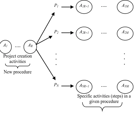
The initial general process at the CRI is given by figure 1 showing
many administrative procedures P1 to PN. Notice all the procedures
have some common activities (Ai1 to AiR). More details will be
[image:2.595.316.555.180.342.2]given in the next section after description of the general process of the CRI.
Fig. 1 Schematic representation of the general process at the CRI, before the streamlining.
3.
WORKFLOW
METHODOLOGY
AS
A
TOOL
FOR
IMPROVING
GOVERNMENT
SERVICES
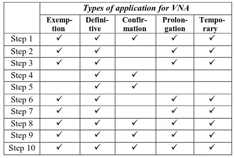
Before the implementation of Flex-Flow, a reengineering of processes was necessary. This was done based on workflow approach and discussed in detail in our previous research [11]. As an example, we present the process reengineering that was undertaken for the ‘Vocation Non Agricole’ (VNA) procedure whose workflow is given in figure 2 and whose steps are defined in table 1 [11]. The model presented is based on workflow methodology. This model is inspired by Information Control Net (ICN) [13]. ICN was created and designed specifically to model office procedures. It captures the control flow, the data flow, goals, actors, roles, and information repositories.
The output of the VNA procedure is the delivery of a certificate that is required for any land developer outside the urban area [12]. This attestation essentially allows an investor to convert an agricultural land to an investment project like a hotel. This procedure involves 10 steps, and some of those steps may be unnecessary, depending on the type of attestation required. In fact, as one can see in table 1, an applicant can trigger one among 5 types of VNA procedures.
The type of procedure triggered by the applicant depends on the characteristics of the land under consideration. In fact, the land can be (i) nude, (ii) already occupied by a project, or (iii) situated in an area covered by a town planning document. In the first case, when the applicant triggers the procedure, he receives a temporary VNA. Upon the completion of the project in a predetermined deadline, noticed by a committee, the applicant receives a confirmative VNA. In the second case, a committee notices the existence of the project,
and the applicant receives a definitive VNA. In the third case, the applicant is provided with an exemption VNA.
Figure 2 shows the initial workflow of VNA procedure, where all steps are executed in sequence, but with some conditions stating whether a particular step is needed.
Those conditions are represented by small diamonds; each one having two outputs, representing two eventualities.
[image:2.595.52.284.214.370.2]The workflow model given in figure 2 has the merit to give a clear view of the procedure of concern, and all steps are transparent for the customer who is a potential investor. This model also facilitates the reengineering phase that is the aim of this subsection.
[image:2.595.353.476.400.745.2]Table 1. Required steps for an VNA procedure, depending on its type. Needed steps are checked.
Fig. 2 Initial workflow of ANAV procedure. Types of application for VNA
Exemp- tion
Defini-
tive
Confir- mation
Prolon- gation
Tempo- rary
Step 1
Step 2
Step 3
Step 4
Step 5
Step 6
Step 7
Step 8
Step 9
Step 10
P1
P2
PN
A1M
A1R
A11
ANM
ANR
AN1
A2M
A2R
A21
Repeated activities
…. ….
Repeated activities
…. ….
. . .
. . .
Repeated activities
…. ….
The steps appearing in table 1 are defined as follows: Step 1: Admissibility of a case file.
Step 2: Sending of the case file to administrations. Step 3: Reception of administrations’ response.
Step 4: Convocation of the commission of official report. Step 5: Decision of the commission of official report.
Step 6: Convocation of committee entrusted with land operations. Step7: Decision of the committee entrusted with land operations. Step 8: Sending of the attestation to the Wali for signature. Step 9: Reception of the attestation signed by the Wali. Step 10: Notification of the investor.
After analysis, we have identified the following opportunities for process improvements.
3.1 Opportunities for parallelism
[image:3.595.310.544.101.236.2]To improve the process in figure 2, we propose to execute the couples tasks (4, 5) and (6, 7), simultaneously. Thus, we obtain the workflow of the new procedure, given in figure 3, where the diamonds with black circles mean that a full split, or a condition rule leading to only one output, can be used, depending on the cases. The parallelism introduced will improve the delays; which is one of BPR’s aims.
Fig. 3 Workflow of the VNA procedure after reengineering.
3.2 Normalizing the process
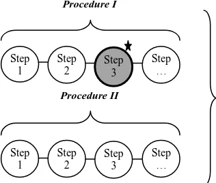
During the VNA procedure, a customer may need to switch to another procedure called ADHOC. In the initial VNA procedure, if such a switching occurs, it is up to the user to remember going back to the initial procedure, and finish the remaining steps. This
[image:3.595.43.285.330.677.2]scenario is described in figure 4 where the procedure II is triggered without any dependency to the ongoing procedure.
Fig. 4 Initial VNA procedure (procedure I), in presence of ADHOC procedure (procedure II).
Because the above scenario can be error prone, we proposed that the workflow has one beginning and one end and make the swiching back to the VNA procedure automatic by clearly defining the dependencies between procedures and let the system track it and remind the user if needed. A scenario emphasizing this fact is given in figure 5 where the execution of step 3 in procedure I is
conditioned to the completion of procedure II.
Fig. 5 VNA procedure, with dependency between the main procedure (procedure I), and the ADHOC one (procedure II).
This normalization will create more satisfaction and less confusion for the user, and ultimately improve the de delivered service.
3.3 Necessity of managing alarms and rules
A workflow system should propose a solution for the management of rules concerning the dependencies among steps in the procedure, the dependencies among procedures, and the management of alarms and delays. In the case of the CRI, there are local regulations that governs the delays of certain procedures, the delays of certain steps, and dependencies among certain procedures
Introducing management of these rules and alarms will facilitate the task for for system users, and will prevent unnecessary delays by alerting users when necessary.
3.4 Necessity of defining roles
The initial procedure, support only the role of a project chief. However, a closer look at the overall process shows that the CRI needs to define different roles and access control for each role [11]. Four roles were proposed; (i) the administrator, (ii) the manager, (iii) the project chief and (iv) the follow up manager.
Step 2
Step 3
Step 4
Step 5
Step 6
Step 7
Step 8
Step 9
Step 10 Step 1
Procedure II
Procedure I
Step 1
Step 2
Step 1
Step 2
Step 3
Step …
Step 3
Step …
Step 1
Step 2
Step 3
Step …
Procedure II Procedure I
Step 1
Step 2
Step 3
Step … Start
Yes If Type = Confirmative No
Conditional full split
If Type = Definitive: use full split
Else if Type = confirmative: execute steps 4 and 5 Else execute steps 6 and 7
Conditional full merge
If Type = Definitive: steps 5 and 7 are required Else: step 5 or 7 is required
[image:3.595.343.501.367.501.2]
The administrator manages overall fixed parameters of the system, The manager executes an internal procedure called “project creation” whose data are necessary for all CRI procedures and assigns the new project to a project chief who then executes the procedures steps, and follows up with the customer (investor).
It is important to note that although the project chief can view data related the current assigned projects, he or she can only modify data related to the procedure. Finally, it is important to notice that projects are assigned to project chiefs, based on their skills. By defining these roles, delimiting access rights to data, and assigning projects based on skills, the CRI becomes more efficient managing its internal data and procedures which contributes to improvement of these government services.
3.5 Consolidating common tasks
In the initial process, when an investor wants to trigger any
administrative procedure, among nine, at this time1, the project
chief enters information related to this procedure, investor information such as name, nationality, passport number (for a foreigner), national card number, whether there is a single investor or an associated group, and investment information such as land, the sector of activity, and investment objectives. Figure 1 gives a schematic representation of the general process with many
procedures P1 to PN. Notice that all the procedures have some
common activities (Ai1 to AiR) which are repeated for each
procedure and thus leading to redundant works and sometimes erroneous data.
To improve the general process at the CRI, we have consolidated
common activities (Ai1 to AiR) in a new internal procedure we
named “project creation”. This procedure is executed before any administrative procedure, and all future executed procedures will benefit from the same data moving forward. The ‘project creation’ procedure has 6 steps and holds key data that need to be consistent for all administrative procedures. These data concern the identification of investor, the identification of project, the investment program, the identification of the land and the infrastructure around the project.
Fig. 6 Schematic representation of the general process at the CRI after streamlining the procedures.
1 In fact, they are forecasting to add other procedures as the CRI expands.
When creating a new project, all needed data about the investor and
investment are stored, and a unique2 project identifier (ID) number
is generated by the system. This ID can be used, later, by the investor, for inquiries and triggering of new procedures; which can leverage existing and historical data. The CRI can also use this ID
number for tracking and reporting. This facilitates the task for both
the investor and government institutions including the CRI.
As shown earlier, the workflow system provided us with the formal methodology and tools for reengineering the general process in the CRI. Concepts like role specifications, alarm settings, traceability, parallelism and normalization, discussed earlier re-configure the government services the CRI provides to investors. The outcomes of the reengineering are essentially better services for investors and better accountability from government institutions.
4.
WORKFLOW
CORPORATE
MEMORY
FACILITATES
PROCESS
IMPROVEMENTS
This section introduces Flex-Flow’s corporate memory (CM) structures and shows how these important data are used for improving CRI processes.
In our previous research [16], we divided CM into three types; (1) organizational memory, (2) work cases memory, and (3) social memory. The first one provides us with general information about how an organization should work (or more precisely, how it is configured to work), the second one emphasizes how it actually works by giving details about current work cases, while the third one captures informal communications relevant to a given work case and provides important data for exception handling. Figure 7 shows the stack of Flex-Flow implementation, Our previous research [16] provides greater details about the stack components and CM structures.
[image:4.595.310.543.486.663.2]The following subsections describe in some details each of the three types of CM and show how the various CM structures of Flex-Flow facilitate process reforms at the CRI.
Fig. 7 Stack of Flex-Flow implementation.
4.1 Organizational corporate memory
This is the type of information provided by workflow systems in general and Flex-Flow in particular [16], before running any instance or work case. Figure 8 shows the organizational structure
2 So long as the triggered procedures belong to a same domain of
activity; otherwise, another ID will be needed.
Client Interface Layer
Procedure Layer
Flex-Flow System Service Layer
Support
Layer Server(s)
Database(s) Role/Right Project
Creation Alarm Management
Session Management
Procedure Management Procedures: P1, P2, P3, P4…
Alarm Setting
Procedure Execution
Configuration Authenti
fication
Correspondences Notes
Organizational Memory
Work cases Memory
Corporate Memory Social
Memory
P1
P2
PN
A1M
A1R+1
ANM
ANR+1
A2M
A2R+1 ….
….
. . .
. . .
….
A1 …. AR
Specific activities (steps) in a given procedure Project creation
activities New procedure
1
[image:4.595.45.286.499.700.2]of Flex-Flow’s CM, describing the relationship between Flex-Flow conceptual entities.
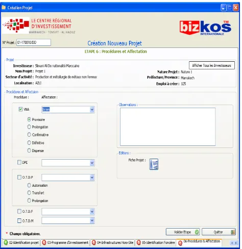
[image:5.595.310.538.120.239.2]From this model, one can derive key information about the organization at hand, namely the roles and access rights, procedural details, and rules that governs process execution at the CRI. As an example, the screen of figure 18 shows the affectation of a VNA procedure to the project chief Ikram. One can also see the list of procedures and their different types, in the current implementation. Hence, this screen emphasizes the existence of an organizational structure before one run of any work case.
Fig. 8 Entity relationship (ER) diagram for the organizational structure of Flex-Flow’s corporate memory.
4.2 Work cases corporate memory
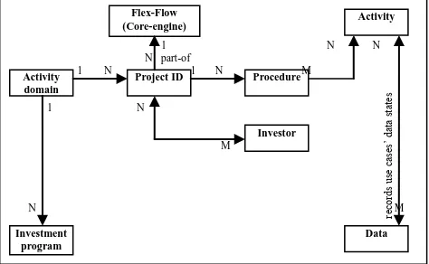
Work cases CM is defined as the collection of information related to instances or use cases that were run or currently running, in the system [16]. From figure 9, one can easily derive all key information related to an investment program carried by a use case in the CRI, giving details such as investment type, sector classification, and investment objectives.
Fig. 9 ER diagram for the use cases structure of Flex-Flow’s corporate memory.
4.3 Social corporate memory
This section will introduce the structure of Flex-Flow’s social CM and how a social tool like ‘Internal Notes’ (IN) provides additional information missed by the formal system. IN is essentially a communication tool which allows all the users of the system, regardless of their roles within an organization, to write up notes to any other user in the system [16]. The notes are intended to mimic “yellow stickers”. IN module is integrated with Flex-Flow so that it is aware of the system organizational and use cases information. Namely current use case ID, role, and procedure at hand. This
[image:5.595.47.287.196.342.2]information provides a context for all informal communication carried out in IN.
Fig. 10 Flex-Flow corporate memory extension.
In summary, the workflow system allows the IN tool to dynamically pull organizational and use cases information, to create a pertinence link between some informal communications and the rest of the workflow information. Figure 10 provides a summary of the above information flow. Our previous research [16] [14] provides greater details about IN design and implementation.
The workflow awareness provides our extended system with the ability to capture structured and distilled informal communication and making it part of the enterprise CM. Without the relevancy link, this social memory could have been lost.
[image:5.595.306.547.436.591.2]The extended data structure contains information relevant to the project, but has no place holder in the formal structure or model. This data is important because it has discussion forums and potential resolutions for exceptions throughout the process and generally useful information on how to handle special circumstances.
Fig. 11 ER diagram for the social structure of Flex-Flow’s corporate memory.
4.4
How
corporate
memory
structures
contribute to process reforms at CRI
Fig.12 Framework for process improvement at CRI
Project ID Activity Activity domain Investment program Investor Flex-Flow engine (Core-engine) Procedure Notes ID Relevancy engine (Core-engine) Data is r eleva nt procedure is relevant re leva nc y N
1 1 N
N part-of N M 1 N 1 N N
1 M N N M N M 1 Flex-Flow (Core-engine)
Project ID Procedure
Activity domain Data Investor Activity Investment program re cor ds us e ca se s’ da ta state s
1 N N N part-of
1 N 1 N M
1 N
M
N M Flex-Flow
(Core-engine)
Procedure Actor
Activity Data Role 1
M M responsible-of
player-of
precedence N N 1 N N M
M
executor-of N used-in
M
Organizational information
Workflow system (WFS)
WFS Interface informs about: -Use cases ID
-Roles -Procedures
-Activities Workflow awareness
Interface Relevan
cy link Social memory
Organization al memory
Use cases memory Extended corporate memory
Traditional corporate memory Extended corporate memory
Improvement Organizational Structure Organizational CM Use cases CM Social CM Use case instance
[image:5.595.44.281.482.628.2] [image:5.595.311.544.685.774.2]While the different types of CM structures contribute differently to process improvement, we have come to notice that they are all linked by common framework for the process improvement. Figure 12 shows the framework for process improvement. In fact, it emphasizes how a use case instance becomes a component of organizational and use cases CM, as it references organizational structure parameters such as roles, rules, procedures, and deadlines. It also gives us a historical log of how the same use case was actually executed in the real world providing project ID, the name of investor, country of origin, investment type, business classification, and timings. In addition, it provides data regarding exceptions that might occur. These combined data becomes the basis for social CM, which provides us a forum for exception handling and problem resolutions through informal communications which constitutes a rich feedback for process improvement.
The following subsections provide some examples of how the framework of figure 12 is carried out.
4.4.1 Reconfiguration of delays
The investor, when engaged in a project and to maintain the various incentives that the state provides, must respect some specific deadlines with regard to project execution. Sometimes, the investor encounters some extraordinary circumstances which block the execution of the investment project. For example, sometimes, there are strikes in some public institutions, which present a hurdle for the investor to meet a specific deadline or certain public institutions simply do not respond in time for some reason or other. While the use cases CM structure provides good data to identify those exceptions, the social CM structure provides the forum to discuss those exceptions and potential remedies [16]. These formal communications have a direct relevancy link to project IDs, investor, and the procedure in question. Management also has access to the same forums and contributes to it like all users. And when an exception persists, the management of the CRI has the ability to reconfigure some aspect of the organization structure and modify the deadlines between certain activities (steps) to make the process closer to the real world experience and thus improving the process for both project chiefs and customers (investors).
4.4.2 Improving workload
When Flex-Flow was initially deployed at the CRI, the manager was entrusted with the execution of the project creation procedure (6 steps), for all procedures. This procedure insures that management validates the key objectives of the investment; which will set the stage for all future administrative procedures undertaken by the investor. While this procedure consolidates the whole process and makes it more efficient for future administrative procedures, it burdens the manager with a lot of works and as a result, the historical use cases clearly showed a slowdown of procedure execution at the managers’ level. To remedy this situation, it was decided to reconfigure the organizational structure and create the new role of ‘under manager’. This new role expanded the right of project chiefs to undertake the task of project creation in their area of expertise, thus distributing the workload cross the various project chiefs and taking advantage of their expertise to expedite the process. It is the feedback from historical use cases and organizational structure that highlighted the need for this reconfiguration and guided the process designers through this improvement.
4.4.3 Handling of required fields and related issues
The management has initially requested that the “*” labeled fields must be provided by project chiefs in any given procedure. To understand the impact of this requirement, we recall from our previous contributions [7][11] that the CRI handles about 10
procedures currently. Each procedure has between 3 and 20 activities, and each procedure must be preceded by the project creation procedure which involves 6 activities. If we assume that each activity has an average of 10 fields, and that 50% of the fields are required, one can imagine the impact of such a requirement. Hence, we have seen many internal notes complaining that users of the system don’t have the needed information to complete the procedure. The management of CRI reacted swiftly and asked the consulting company to provide the mean for handling these exceptions.
The consulting company introduced a solution to bypass the mandatory fields requirements and interpret those fields as ‘not available’. As a result, the user should be allowed to carry on the procedures and generated documents that are currently over 60, will show “ND” for not available data. This solution helped all the parties to embrace the new system. In fact, in a six months period, over 700 projects were created in the system, and users have great appreciation of the system as it helps them automate various tasks.
5.
FLEXFLOW
DEPLOYMENT
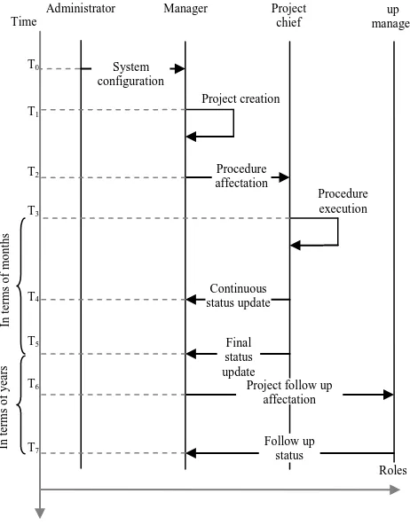
Figure 13, shows the framework interactions among the different
stakeholders involved in its management, through time (from T0 to
T7). The administrator first configures the system and creates the
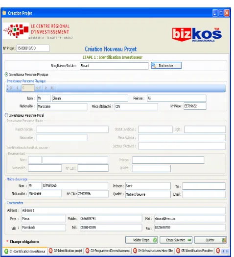
[image:6.595.306.537.404.700.2]users’ accounts. After, upon the request of an investor, the manager creates a new project, triggers the requested procedure and affect it to a project chief. Figure 14 through Figure 18 provide some user interfaces for this phase. The project chief then executes the procedure and sends, continuously, information about the current status to the manager, as well as the final status when the procedure is achieved. Figure 19 provide a sample screen for the VNA procedure,
Fig. 13 The framework interactions among the different stakeholders involved in the management of Flex-Flow.
Administrator Manager Project
chief
Follow up manager
System configuration
Project creation
Procedure affectation
Continuous status update
Final status update
Project follow up affectation
Procedure execution
Follow up status
Roles Time
T0
T1
T2
T3
T4
T5
T6
T7
In
ter
ms
of
ye
ar
s
In
ter
ms
of
mont
Fig. 14 Sample screen, project creation: creation of an investor object.
[image:7.595.49.285.70.322.2]Fig. 15 Sample screen, project creation: identification of the investor.
Fig. 16 Sample screen, project creation: filling of project information: identification of project.
[image:7.595.48.287.363.625.2] [image:7.595.314.549.367.626.2]Fig. 18 Sample screen, project creation: assigning the project to AVNA project chief.
Fig. 19 Sample screen, VNA procedure
6.
CONCLUSION
This paper was concerned with the investigation about the relationship between workflow systems and e-governance. In fact, it has demonstrated that workflow systems are a tool for the implementing e-government services. In addition, workflow methodologies and solutions provide the framework needed for process modelling, re-engineering, and enhancement. We are currently in the process of collecting user’s feedback. We intend
to provide future enhancements and integrated tools that will leverage current workflow system structures, including CM structures, to provide decision support at key areas of the systems.
For example, we intend to provide decision support module that will help assess the aggregate infrastructure requirements for existing and prospective projects, and help in impact analysis. For this reason, we also foresee integrating geographical information
system (GIS) to provide relevant geographical data.
REFERENCES
[1] Manorama T., “Lokvani (voice of the masses): A case study of e-governance in rural India,” The International Information & Library Review, vol. 39, no. 3-4, pp. 194-202, 2007.
[2] Mohanty P. K., “Using e-Tools for Good Governance & Administrative Reforms,” available at http://www.cgg.gov.in/workingpapers/eGovPaperARC.pdf. [3] Susana K. M. et al., “Workflow Based e-Governance
Applications: Case Study of Wf-Bhulekh,” available at http://www.csi-sigegov.org/2/22_317_2.pdf.
[4] Shivanthi W., “Revolution within the evolution: the Sri Lankan attempt to bridge the digital divide through e-governance,” The International Information & Library Review, vol. 36, no. 4, pp. 319–327, 2004.
[5] Maria N. et al., “Agricultural e-government services: An implementation framework and case study,” Computers and Electronics in Agriculture , vol. 70 , no. 2, pp. 337–347, 2010. [6] LT Sharon M. B., Magdi N. K., “Workflow Reengineering: A
Methodology for Business Process Reengineering Using Workflow Management Technology,” in Proceedings of The Thirtieth Annual Hawwaii International Conference on System Sciences, Hawwaii, USA, 1997.
[7] De Jager A., Van Reijswoud V., “E-Governance in the developing world in action: the case of DistrictNet in Uganda,”
The Journal of Community Informatics, vol. 4, no. 2, Special Issue: E-Governance and Community Informatics, 2008.
[8] Protis Consulting, “Business Process Reengineering,” available at http://www.protis-consulting.com/pdf/2-brp.pdf
[9] Selmin N. L., “Processus coopératifs et workflow, ” available at http://crinfo.univ-paris1.fr/users/nurcan/pc_wf.html.
[10] Soubbarayer S., “Les enjeux du workflow,” in Proceedings of IT FORUM'94, Télécom Paris, Paris, France, 1994.
[11] El Khadiri M. and El Fazziki A., “How workflow approach can facilitate Business Process Reengineering: A case study in Marrakech,” in Proceedings of International Workshop about Industrial and Logistic Systems, Marrakech, Morocco, 2010. [12] www.crimarrakech.ma, Accessed on jully, 2011
[13] Ellis C. A. and Keddara K., “Dynamic Change Within Workflow Systems,” CU-CS-667-93, University of Colorado, Department of Computer Science, August 1993.
[14] El Khadiri M., El Fazziki A., Clarance (Skip) E., “Enterprise workflow, corporate memory, and decision-making,” in Proceedings of International Conference on Multimedia Computing and Systems, Ouarzazate, Morocco, 2011.
[15] www.bizkos.com/Notes_Internes.pdf, Accessed January 2012. [16] El khadiri. M., and El fazziki. A.: “Extended Corporate
[image:8.595.311.549.70.317.2]