Experimental Investigation on the Shear Behaviour of Concrete Beams
Reinforced with GFRP Reinforcement Bars
Noor Azlina Abdul Hamid
1, 2, a, Azmi Ibrahim
2, b, Rendy Thamrin
3, cand Hanizah Abdul Hamid
2, d1
Faculty of Civil and Environmental Engineering, Universiti Tun Hussein Onn Malaysia, Johor, Malaysia
2
Faculty of Civil Engineering, Universiti Teknologi Mara, Shah Alam, Selangor, Malaysia 3
Faculty of Engineering, Universiti Andalas, Padang, Indonesia a
azlinah@uthm.edu.my, bazmii716@yahoo.com, crendy@ft.unand.ac.id, dhanizah_ah@yahoo.com
Keywords: reinforced concrete beams, GFRP bars, shear behaviour, stirrups
Abstract. This paper presents the experimental results of shear behaviour on concrete beams longitudinally reinforced with glass fiber-reinforced polymer (GFRP) reinforcement bars. Totally sixteen concrete beams were tested under static load. Half of the tested beams were longitudinally reinforced with GFRP reinforcement bars, while, the other half were reinforced with conventional steel reinforcement bars. The beams were prepared with varying test variables, such as shear span-to-effective depth ratios (a/d), amount and types of longitudinal reinforcement bars and stirrup spacing. The experimental results show that the ratios of a/d and stirrup spacing significantly influence the ultimate capacities of the beams. Moreover, more closely spaced diagonal shear cracks were resulted in GFRP reinforced concrete (RC) beams compared to steel RC beams.
Introduction
Commercially, fiber-reinforced polymer (FRP) is available in the form of carbon, aramid and glass fibres. Due to superior advantages compared to steel, the increasing consideration for use in civil infrastructures applications ranging from new construction structural system to the repair and rehabilitation works grow rapidly over the past decades. In addition, the utilization of FRP composites as a reinforcing material in concrete structure, including its flexibility which can be formed as continuous sheets, rods and plates, has raised high concerns among industries and researchers on the feasibility of FRPs [1]. Moreover, a new innovation of hybrid structural system which combines FRP composites and conventional structural materials such steel and concrete, currently being a major focus for the future direction of FRP composites [2].
In comparison among types of FRP, GFRP possesses the lowest tensile strength but it has the advantage of being least expensive. However, this composite material has proven to have high strength and to be noncorrosive and lightweight relative to the conventional steel. Research works related to the use of GFRP bars to replace longitudinal steel bars have been performed [3-6]. Nevertheless, very little research has been conducted to study the shear behaviour of FRP RC beams due to the difficulty in understanding its mechanism of failure. In addition, due to the incomparable strength of steel and FRP, different consideration of design concepts would affect the shear performance of the beam. Test results have shown that GFRP RC beams without shear reinforcement failed in shear for over-reinforced beams, whereas beam in under-reinforced section failed in flexure with excessive deflection [4]. Even, beam with GFRP stirrups failed in a flexure-shear mode, and it also indicate that as the amount of longitudinal bars increases the flexure-shear strength is also increased [7]. Thus, according to previous study, further research is needed in understanding the shear performance of GFRP beams with different test variables.
Experimental Investigation on the Shear Behaviour of Concrete Beams
Reinforced with GFRP Reinforcement Bars
Noor Azlina Abdul Hamid
1, 2, a, Azmi Ibrahim
2, b, Rendy Thamrin
3, cand Hanizah Abdul Hamid
2, d1
Faculty of Civil and Environmental Engineering, Universiti Tun Hussein Onn Malaysia, Johor, Malaysia
2
Faculty of Civil Engineering, Universiti Teknologi Mara, Shah Alam, Selangor, Malaysia 3
Faculty of Engineering, Universiti Andalas, Padang, Indonesia a
azlinah@uthm.edu.my, bazmii716@yahoo.com, crendy@ft.unand.ac.id, dhanizah_ah@yahoo.com
Keywords: reinforced concrete beams, GFRP bars, shear behaviour, stirrups
Abstract. This paper presents the experimental results of shear behaviour on concrete beams longitudinally reinforced with glass fiber-reinforced polymer (GFRP) reinforcement bars. Totally sixteen concrete beams were tested under static load. Half of the tested beams were longitudinally reinforced with GFRP reinforcement bars, while, the other half were reinforced with conventional steel reinforcement bars. The beams were prepared with varying test variables, such as shear span-to-effective depth ratios (a/d), amount and types of longitudinal reinforcement bars and stirrup spacing. The experimental results show that the ratios of a/d and stirrup spacing significantly influence the ultimate capacities of the beams. Moreover, more closely spaced diagonal shear cracks were resulted in GFRP reinforced concrete (RC) beams compared to steel RC beams.
Introduction
Commercially, fiber-reinforced polymer (FRP) is available in the form of carbon, aramid and glass fibres. Due to superior advantages compared to steel, the increasing consideration for use in civil infrastructures applications ranging from new construction structural system to the repair and rehabilitation works grow rapidly over the past decades. In addition, the utilization of FRP composites as a reinforcing material in concrete structure, including its flexibility which can be formed as continuous sheets, rods and plates, has raised high concerns among industries and researchers on the feasibility of FRPs [1]. Moreover, a new innovation of hybrid structural system which combines FRP composites and conventional structural materials such steel and concrete, currently being a major focus for the future direction of FRP composites [2].
Experimental Program
In this study, the comparison was made between the shear performance of steel and GFRP RC beams which identified as BSM and BGM respectively. Totally sixteen RC beams were designated with different amount and types of longitudinal reinforcement bars, a/d and steel stirrup ratios (refer Table 1). Eight specimens were longitudinally reinforced with 16 mm diameter of steel bars, while another eight specimens reinforced with 16 mm diameter of GFRP bars. The beam dimension was 200 mm wide, 400 mm deep with 2000 mm and 3000 mm long due to two types of shear span length (a = 550 mm and 1100 mm). The beams were designed accordingly to available design codes and guidelines in the literature [8-10]. Two design codes of “Structural Use of Concrete – BS8110-1:1997” and “Building Code Requirements for Structural Concrete and Commentary – ACI 318-08” were used for the design of steel RC beams. Since the designation of FRP reinforced concrete beams are slightly differ from conventional beams, the code provisions according to the “Guide for the Design and Construction of Structural Concrete Reinforced with FRP Bars – ACI 440.1R-06” was used.
[image:2.595.94.497.403.676.2]In this study, the failure modes of BSM are governs by steel yielding before the concrete strain at the compression area reached the maximum permissible value of 0.0035 [11]. For shear reinforcement, 2-legged steel stirrups of 8 mm diameter (mild steel) were spaced at 50 mm and 150 mm centre to centre at the shear region. These two kinds of spacing were calculated based on BS8110 code provisions in order to investigate the shear performance of the beams with minimum and adequate amount of stirrups. In each specimen, strain gauges were position at selected locations at longitudinal bars, stirrups and concrete which were labelled as X (see Fig. 1). The deflection of the beam was measured by at mid-span and two loading points.
Table 1. Detail of test variables
Material Properties. All specimens were cast with normal grade concrete with a targeted compressive strength on the 28-days as 30 MPa. Ready-mixed concrete was used with 20 mm maximum aggregate size. From direct tensile test, elastic modulus of 207 GPa, yield stress of 512 MPa and yield strain of 0.0026 were obtained for steel bars in BSM specimens. While in BGM specimens, sand-coated GFRP V-Rods that manufactured by pultrusion process which comprise of E-glass fibres in vinyl ester resin matrix were used. The mechanical properties of GFRP bars were used accordingly from the specification provided by manufacturers. The tensile strength, modulus
Specimens a a/d L La Lt ot al
(mm) (mm) (mm) (mm) s (mm) ρs (%) N ρs = ρs' (%)
BSM-01 550 1.6 1500 250 2000 50 1.01 2 0.6
BSM-02 550 1.6 1500 250 2000 50 1.01 3 0.9
BSM-03 550 1.6 1500 250 2000 150 0.34 2 0.6
BSM-04 550 1.6 1500 250 2000 150 0.34 3 0.9
BSM-05 1100 3.1 2600 200 3000 50 1.01 2 0.6
BSM-06 1100 3.1 2600 200 3000 50 1.01 3 0.9
BSM-07 1100 3.1 2600 200 3000 150 0.34 2 0.6
BSM-08 1100 3.1 2600 200 3000 150 0.34 3 0.9
BGM-01 550 1.6 1500 250 2000 50 1.01 2 0.6
BGM-02 550 1.6 1500 250 2000 50 1.01 3 0.9
BGM-03 550 1.6 1500 250 2000 150 0.34 2 0.6
BGM-04 550 1.6 1500 250 2000 150 0.34 3 0.9
BGM-05 1100 3.1 2600 200 3000 50 1.01 2 0.6
BGM-06 1100 3.1 2600 200 3000 50 1.01 3 0.9
BGM-07 1100 3.1 2600 200 3000 150 0.34 2 0.6
BGM-08 1100 3.1 2600 200 3000 150 0.34 3 0.9
Shear Reinforcement
Longitudinal Reinforcement
Experimental Program
In this study, the comparison was made between the shear performance of steel and GFRP RC beams which identified as BSM and BGM respectively. Totally sixteen RC beams were designated with different amount and types of longitudinal reinforcement bars, a/d and steel stirrup ratios (refer Table 1). Eight specimens were longitudinally reinforced with 16 mm diameter of steel bars, while another eight specimens reinforced with 16 mm diameter of GFRP bars. The beam dimension was 200 mm wide, 400 mm deep with 2000 mm and 3000 mm long due to two types of shear span length (a = 550 mm and 1100 mm). The beams were designed accordingly to available design codes and guidelines in the literature [8-10]. Two design codes of “Structural Use of Concrete – BS8110-1:1997” and “Building Code Requirements for Structural Concrete and Commentary – ACI 318-08” were used for the design of steel RC beams. Since the designation of FRP reinforced concrete beams are slightly differ from conventional beams, the code provisions according to the “Guide for the Design and Construction of Structural Concrete Reinforced with FRP Bars – ACI 440.1R-06” was used.
In this study, the failure modes of BSM are governs by steel yielding before the concrete strain at the compression area reached the maximum permissible value of 0.0035 [11]. For shear reinforcement, 2-legged steel stirrups of 8 mm diameter (mild steel) were spaced at 50 mm and 150 mm centre to centre at the shear region. These two kinds of spacing were calculated based on BS8110 code provisions in order to investigate the shear performance of the beams with minimum and adequate amount of stirrups. In each specimen, strain gauges were position at selected locations at longitudinal bars, stirrups and concrete which were labelled as X (see Fig. 1). The deflection of the beam was measured by at mid-span and two loading points.
Table 1. Detail of test variables
Material Properties. All specimens were cast with normal grade concrete with a targeted compressive strength on the 28-days as 30 MPa. Ready-mixed concrete was used with 20 mm maximum aggregate size. From direct tensile test, elastic modulus of 207 GPa, yield stress of 512 MPa and yield strain of 0.0026 were obtained for steel bars in BSM specimens. While in BGM specimens, sand-coated GFRP V-Rods that manufactured by pultrusion process which comprise of E-glass fibres in vinyl ester resin matrix were used. The mechanical properties of GFRP bars were used accordingly from the specification provided by manufacturers. The tensile strength, modulus
Specimens a a/d L La Lt ot al
(mm) (mm) (mm) (mm) s (mm) ρs (%) N ρs = ρs' (%)
BSM-01 550 1.6 1500 250 2000 50 1.01 2 0.6
BSM-02 550 1.6 1500 250 2000 50 1.01 3 0.9
BSM-03 550 1.6 1500 250 2000 150 0.34 2 0.6
BSM-04 550 1.6 1500 250 2000 150 0.34 3 0.9
BSM-05 1100 3.1 2600 200 3000 50 1.01 2 0.6
BSM-06 1100 3.1 2600 200 3000 50 1.01 3 0.9
BSM-07 1100 3.1 2600 200 3000 150 0.34 2 0.6
BSM-08 1100 3.1 2600 200 3000 150 0.34 3 0.9
BGM-01 550 1.6 1500 250 2000 50 1.01 2 0.6
BGM-02 550 1.6 1500 250 2000 50 1.01 3 0.9
BGM-03 550 1.6 1500 250 2000 150 0.34 2 0.6
BGM-04 550 1.6 1500 250 2000 150 0.34 3 0.9
BGM-05 1100 3.1 2600 200 3000 50 1.01 2 0.6
BGM-06 1100 3.1 2600 200 3000 50 1.01 3 0.9
BGM-07 1100 3.1 2600 200 3000 150 0.34 2 0.6
BGM-08 1100 3.1 2600 200 3000 150 0.34 3 0.9
Shear Reinforcement
of elasticity and ultimate strain of the bars are 920 MPa, 56779 MPa and 1.6% respectively. As for shear reinforcement, vertical steel stirrups with elastic modulus of 162 GPa, yield stress of 440 MPa and yield strain of 0.0028 were obtained from the tensile test.
[image:3.595.113.428.128.236.2]
Figure 1. Tested specimen of BSM-03 and BSM-04
Experimental Results and Discussion
The test results obtained from the experimental program were summarized (refer Table 2).
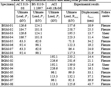
Table 2. Experimental results and analytical predictions
Since the beams were prepared with different shear span length, significant influence can be seen from two types of failure mode. It is clearly shown that the beams with lesser a/d ratio (i.e.; BSM-01 to BSM-04) experienced higher capacity compared to beams which have greater a/d ratios (i.e.; BSM-05 to BSM-08). Similar results was found in beams which reinforced with GFRP bars i.e.; BGM-01 with 1.6 a/d ratios exhibit high capacity up to 233.2 kN rather than BGM-05 with a/d=3.1 that only reached 99.0 kN when it failed. It is shown that the ultimate capacity increases as the shear span-to-depth ratios decreases. In addition, two modes of failure, shear and flexure were observed from the test results. Sudden formation of diagonal crack can be found in the shear span zone followed by beam failure (BSM-03, BSM-04, BGM-03 and BGM-04). Additionally, the inclination of shear cracks growth rapidly as the load increase. While, beam failed in flexure experienced by one of the following condition i.e.; rupture of tensile longitudinal reinforcement for beam BGM-01, BGM-05, BGM-06, BGM-07 and BGM-08 and also concrete crushing on the top of
P P
400 mm
a a
La La
L X
X
X X X
X X
X X X
As'
As
200 mm
3
5
4
m
m
Specimens ACI 318-08
BS 8110-1:1997
ACI 440.1R-06 Ultimate
Load, Pf
Ultimate Load, Pf
Ultimate Load, Pf
Ultimate Load, Pmax
Displacement, δmax
Failure mode
(kN) (kN) (kN) (kN) (mm)
BSM-01 126.6 124.1 157.6 10.9 Flexure
BSM-02 184.7 181.8 258.7 25.5 Flexure
BSM-03 126.6 124.1 195.5 13.7 Shear
BSM-04 186.7 181.8 223.3 11.4 Shear
BSM-05 63.3 62.0 71.8 34.2 Flexure
BSM-06 92.4 90.1 122.3 19.2 Flexure
BSM-07 63.3 62.0 86.4 24.0 Flexure
BSM-08 92.4 90.1 117.3 21.9 Flexure
BGM-01 192.1 233.2 14.4 Flexure
BGM-02 226.6 281.6 21.1 Flexure
BGM-03 192.1 139.0 12.6 Shear
BGM-04 226.6 181.3 16.1 Shear
BGM-05 96.1 99.0 33.1 Flexure
BGM-06 113.3 132.1 37.1 Flexure
BGM-07 96.1 92.8 39.9 Flexure
BGM-08 113.3 125.6 43.7 Flexure
Experimental results
of elasticity and ultimate strain of the bars are 920 MPa, 56779 MPa and 1.6% respectively. As for shear reinforcement, vertical steel stirrups with elastic modulus of 162 GPa, yield stress of 440 MPa and yield strain of 0.0028 were obtained from the tensile test.
[image:3.595.126.483.322.604.2]
Figure 1. Tested specimen of BSM-03 and BSM-04
Experimental Results and Discussion
The test results obtained from the experimental program were summarized (refer Table 2).
Table 2. Experimental results and analytical predictions
Since the beams were prepared with different shear span length, significant influence can be seen from two types of failure mode. It is clearly shown that the beams with lesser a/d ratio (i.e.; BSM-01 to BSM-04) experienced higher capacity compared to beams which have greater a/d ratios (i.e.; BSM-05 to BSM-08). Similar results was found in beams which reinforced with GFRP bars i.e.; BGM-01 with 1.6 a/d ratios exhibit high capacity up to 233.2 kN rather than BGM-05 with a/d=3.1 that only reached 99.0 kN when it failed. It is shown that the ultimate capacity increases as the shear span-to-depth ratios decreases. In addition, two modes of failure, shear and flexure were observed from the test results. Sudden formation of diagonal crack can be found in the shear span zone followed by beam failure (BSM-03, BSM-04, BGM-03 and BGM-04). Additionally, the inclination of shear cracks growth rapidly as the load increase. While, beam failed in flexure experienced by one of the following condition i.e.; rupture of tensile longitudinal reinforcement for beam BGM-01, BGM-05, BGM-06, BGM-07 and BGM-08 and also concrete crushing on the top of
P P
400 mm
a a
La La
L X
X
X X X
X X
X X X
As'
As
200 mm
3
5
4
m
m
Specimens ACI 318-08
BS 8110-1:1997
ACI 440.1R-06 Ultimate
Load, Pf
Ultimate Load, Pf
Ultimate Load, Pf
Ultimate Load, Pmax
Displacement, δmax
Failure mode
(kN) (kN) (kN) (kN) (mm)
BSM-01 126.6 124.1 157.6 10.9 Flexure
BSM-02 184.7 181.8 258.7 25.5 Flexure
BSM-03 126.6 124.1 195.5 13.7 Shear
BSM-04 186.7 181.8 223.3 11.4 Shear
BSM-05 63.3 62.0 71.8 34.2 Flexure
BSM-06 92.4 90.1 122.3 19.2 Flexure
BSM-07 63.3 62.0 86.4 24.0 Flexure
BSM-08 92.4 90.1 117.3 21.9 Flexure
BGM-01 192.1 233.2 14.4 Flexure
BGM-02 226.6 281.6 21.1 Flexure
BGM-03 192.1 139.0 12.6 Shear
BGM-04 226.6 181.3 16.1 Shear
BGM-05 96.1 99.0 33.1 Flexure
BGM-06 113.3 132.1 37.1 Flexure
BGM-07 96.1 92.8 39.9 Flexure
BGM-08 113.3 125.6 43.7 Flexure
0 100 200 300 400
0 100 200 300 400
B
G
M
E
x
p
. U
lt
. L
o
a
d
(
k
N
)
BSM Exp. Ult. Load (kN) a/d = 1.6
a/d = 3.1
compression zone in beam BSM-01, BSM-02, BSM-05 to BSM-06 and BGM-02. In addition, the occurrence of cracks in shorter shear span length less than that beam with longer shear span length (see Figure 2).
a) RC beams with a/d = 1.6
[image:4.595.59.530.150.298.2]b) RC beams with a/d = 3.1
Figure 2. Crack patterns between steel (BSM) and GFRP (BGM) RC beams
[image:4.595.84.510.442.774.2]Large numbers of closely spaced cracks were seen in GFRP RC beams compared to steel RC beams. Due to higher tensile strength of GFRP bars, the capacity between BGM and BSM is slightly higher (Fig. 3). In beam which was designed with closer stirrups exhibited higher amount of shear capacity compared to beam with lower stirrup ratios. Moreover, the shear capacity of BGM specimens was slightly higher than BSM specimens. However, in case of beams failed in shear i.e.; BSM-03, BSM-04, BGM-03 and BGM-04, the ultimate loads and also the shear capacity of stirrups in BGM was lower than BSM (Fig. 4). Thus, the expected shear failure was achieved due to lower a/d and stirrups ratio provided in the beams.
Figure 3. Experimental ultimate loads between BSM and BGM
a) BSM-03 (a/d = 1.6, s = 150 mm) b) BGM-03 (a/d = 1.6, s = 150 mm)
Figure 4. Strains recorded in stirrups for beams failed in shear
0 100 200 300 400
0 100 200 300 400
B
G
M
E
x
p
. U
lt
. L
o
a
d
(
k
N
)
BSM Exp. Ult. Load (kN) a/d = 1.6
a/d = 3.1
compression zone in beam BSM-01, BSM-02, BSM-05 to BSM-06 and BGM-02. In addition, the occurrence of cracks in shorter shear span length less than that beam with longer shear span length (see Figure 2).
a) RC beams with a/d = 1.6
b) RC beams with a/d = 3.1
Figure 2. Crack patterns between steel (BSM) and GFRP (BGM) RC beams
[image:4.595.209.378.444.578.2]Large numbers of closely spaced cracks were seen in GFRP RC beams compared to steel RC beams. Due to higher tensile strength of GFRP bars, the capacity between BGM and BSM is slightly higher (Fig. 3). In beam which was designed with closer stirrups exhibited higher amount of shear capacity compared to beam with lower stirrup ratios. Moreover, the shear capacity of BGM specimens was slightly higher than BSM specimens. However, in case of beams failed in shear i.e.; BSM-03, BSM-04, BGM-03 and BGM-04, the ultimate loads and also the shear capacity of stirrups in BGM was lower than BSM (Fig. 4). Thus, the expected shear failure was achieved due to lower a/d and stirrups ratio provided in the beams.
Figure 3. Experimental ultimate loads between BSM and BGM
a) BSM-03 (a/d = 1.6, s = 150 mm) b) BGM-03 (a/d = 1.6, s = 150 mm)
Conclusions
Based on the test results presented in this paper, the following conclusions can be drawn:
• Beams with lesser a/d ratios shows higher ultimate capacity compared to beam with greater a/d ratios.
• Shear capacity of GFRP RC beams is lower compared to steel RC beams.
• The use of GFRP bars as longitudinal reinforcement bars affect the shear performance and patterns of cracking.
• High amount of GFRP bars increased the ultimate capacity and deflection of the beams.
• Closes diagonal cracks significantly developed in GFRP RC beams.
• Higher strain values were recorded on stirrups in beam reinforced with GFRP bars rather than stirrups in steel RC beams.
Acknowledgements
The experimental work presented in this paper was conducted in the Heavy Structures Laboratory of Univ. Tun Hussein Onn Malaysia and Univ. Teknologi Mara, Shah Alam which supervised under Dr. Rendy Thamrin and Prof. Dr. Azmi Ibrahim. All support is gratefully acknowledged.
References
[1]. T. Uomoto, H. Mutsuyoshi, F. Katsuki, and S. Misra, Use of Fiber Reinforced Polymer Composites as Reinforcing Material for Concrete. Journal of Materials in Civil Engineering, 2002.14(3): p. 191-209.
[2]. L.C. Hollaway, A Review of the Present and Future Utilisation of FRP Composites in the Civil Infrastructure with Reference to their Important In-Service Properties Journal of Construction and Building Materials, 2010. 24: p. 2419-2445.
[3]. F.M. Wegian, and H.A. Abdalla, Shear Capacity of Concrete Beams Reinforced with Fiber Reinforced Polymers. Journal of Composite Structures, 2005. 71: p. 130-138.
[4]. A.F. Ashour, Flexural and shear capacities of concrete beams reinforced with GFRP bars.
Construction and Building Materials, 2006. 20(10): p. 1005-1015.
[5]. M. Guadagnini, K. Pilakoutas, and P. Waldron, Shear Resistance of FRP RC Beams: Experimental Study. Journal of Composites for Construction, 2006. 10(6): p. 464-473. [6]. T. Stratford, and C. Burgoyne, Shear Analysis of Concrete with Brittle Reinforcement.
Journal of Composites for Construction, 2003. 7(4): p. 323-330.
[7]. T. Alkhrdaji, M. Wideman, A. Belarbi and A. Nanni, Shear Strength of GFRP RC Beams and Slabs. Proc. CCC 2001, Composites in Construction, Porto Portugal, L.Juvandes and R.Furia, Eds., 2001: p. 409-414.
[8]. British Standard Institution (BSI), BS 8110-1: 1997 Structural Use of Concrete, Code of Practice for Design and Construction, Part 1, BSI, London. 1997: p. 172.
[9]. American Concrete Institut (ACI), Building Code Requirements for Structural Concrete (ACI 318-08) and Commentary. American Concrete Institute, Farmington Hills (MI), 2008: p. 465.
[10]. American Concrete Institut (ACI), Guide for the Design and Construction of Structural Concrete Reinforced with FRP Bars (440.1R-06). 2006: p. 44.
[11]. P. Bhatt, T.J. MacGinley, and B.S. Choo, Reinforced Concrete, Design Theory and Examples, Third Edition, Taylor & Francis, 2006: p. 583.
Conclusions
Based on the test results presented in this paper, the following conclusions can be drawn:
• Beams with lesser a/d ratios shows higher ultimate capacity compared to beam with greater a/d ratios.
• Shear capacity of GFRP RC beams is lower compared to steel RC beams.
• The use of GFRP bars as longitudinal reinforcement bars affect the shear performance and patterns of cracking.
• High amount of GFRP bars increased the ultimate capacity and deflection of the beams.
• Closes diagonal cracks significantly developed in GFRP RC beams.
• Higher strain values were recorded on stirrups in beam reinforced with GFRP bars rather than stirrups in steel RC beams.
Acknowledgements
The experimental work presented in this paper was conducted in the Heavy Structures Laboratory of Univ. Tun Hussein Onn Malaysia and Univ. Teknologi Mara, Shah Alam which supervised under Dr. Rendy Thamrin and Prof. Dr. Azmi Ibrahim. All support is gratefully acknowledged.
References
[1]. T. Uomoto, H. Mutsuyoshi, F. Katsuki, and S. Misra, Use of Fiber Reinforced Polymer Composites as Reinforcing Material for Concrete. Journal of Materials in Civil Engineering, 2002.14(3): p. 191-209.
[2]. L.C. Hollaway, A Review of the Present and Future Utilisation of FRP Composites in the Civil Infrastructure with Reference to their Important In-Service Properties Journal of Construction and Building Materials, 2010. 24: p. 2419-2445.
[3]. F.M. Wegian, and H.A. Abdalla, Shear Capacity of Concrete Beams Reinforced with Fiber Reinforced Polymers. Journal of Composite Structures, 2005. 71: p. 130-138.
[4]. A.F. Ashour, Flexural and shear capacities of concrete beams reinforced with GFRP bars.
Construction and Building Materials, 2006. 20(10): p. 1005-1015.
[5]. M. Guadagnini, K. Pilakoutas, and P. Waldron, Shear Resistance of FRP RC Beams: Experimental Study. Journal of Composites for Construction, 2006. 10(6): p. 464-473. [6]. T. Stratford, and C. Burgoyne, Shear Analysis of Concrete with Brittle Reinforcement.
Journal of Composites for Construction, 2003. 7(4): p. 323-330.
[7]. T. Alkhrdaji, M. Wideman, A. Belarbi and A. Nanni, Shear Strength of GFRP RC Beams and Slabs. Proc. CCC 2001, Composites in Construction, Porto Portugal, L.Juvandes and R.Furia, Eds., 2001: p. 409-414.
[8]. British Standard Institution (BSI), BS 8110-1: 1997 Structural Use of Concrete, Code of Practice for Design and Construction, Part 1, BSI, London. 1997: p. 172.
[9]. American Concrete Institut (ACI), Building Code Requirements for Structural Concrete (ACI 318-08) and Commentary. American Concrete Institute, Farmington Hills (MI), 2008: p. 465.
[10]. American Concrete Institut (ACI), Guide for the Design and Construction of Structural Concrete Reinforced with FRP Bars (440.1R-06). 2006: p. 44.