Journal of Chemical and Pharmaceutical Research, 2013, 5(12):681-689
Research Article
CODEN(USA) : JCPRC5
ISSN : 0975-7384
Robot vision system design and implementation based on Open CV
Jiansheng Peng
1,2, Qingjin Wei
2, Qiwen He
2,
Yong Qin
2,
Zhuocheng Huang
2, Yiyong
Huang
2,
Marong Pan
2, Baoying Lin
2, Degui Yang
2, Siyuan Luo
2and Changfeng Liang
21
National Key Laboratory of Communication, UEST of China Chengdu, China
2
Department of Physics and Mechanical & Electronic Engineering, Hechi University, Yizhou, China
_____________________________________________________________________________________________
ABSTRACT
Studying Combined OpenCV image processing algorithm libraries with machine vision technology, build a robot vis ion system. OpenCV vision algorithm is the core of the system, dual cameras as the system input, using VC++ 6.0 pr ogram interface and tools to write Windows applications, build a robot vision system architecture. By way of the dev elopment environment is configured correctly, make use of the function of OpenCV algorithms, vision measurement t echnology, video processing and image processing technology, and to improve and optimize the vision algorithms to achieve camera calibration, realize Camera single and binocular target calibration, and improve the calibration ac curacy and speed. To through Optimize the OpenCV vision algorithms applied to robot vision measurement, the Ope nCV algorithms plays a better role in enhancing the visual measurement speed and accuracy. Shorten the developm ent cycle of the visual system and Shorten the development cycle of the visual system.
Key words: Machine vision measurement, OpenCV, camera calibration
_____________________________________________________________________________________________
INTRODUCTION
In the field of robot control, visual control is currently an important research direction and ones of the hotspots in the current. Robot vision measurement is not only an important research to robot vision of control, but also to achieve the basic of visual control. Robot vision measurement system is instead of human eyes to identification, track and measure the target use the machines[1,4]. Currently, both at home and abroad have studied robot vision measurement technology and achieved good research. In the early days, robot vision measurement just studied for two-dimensional vision measurement, such as Adept robotic assembly systems, robot soccer and so on in the United States[5,8]. However, in the two-dimensional vision measurement system, the distance between the camera and the measure plane must be fixed, therefore, makes the application of two-dimensional vision measurement system subject to greater restrictions. The center of Xi'an Jiaotong university CIMS to establish the line laser - Machine Vision Measuring System, the measurement system principally multi-sensor fusion technology[9,10]. Sensor data Since a single can not be extracted enough information to complete the application-specific tasks, so take multi-sensor information fusion, capturing more information, reducing the ambiguity of understanding, improve the efficiency of data.
SYSTEM ARCHITECTURE Function and Structure
Image acquisition
System of robot vision
Camera Calibration
Monocular
Calibration calibrationBinocular
Calibratio n results show Camera
start processingImage
Fig.1 Robot vision system function block diagram
The system to divide module is based on visual measurement of camera calibration principle, each module to complete the corresponding function:
Camera Start: As an input of system and is responsible for establishment a interact bridge of system software and outside information. In the implementation of single-target timing, you need to switch and select start the camera, and in the twin goals of the timing, they have to start two cameras.
Image Acquisition: acquiring image frames according to a certain rate through the camera, available to the visual system for image processing or video processing.
Image processing: for the camera to get some raw image processing, in order to get a better results of camera calibration.
Single target set: solving the camera of internal and external parameters to determine the relative position of the camera.
Binocular Calibration: Solving the structural parameters between cameras that measure the geometry between the two cameras.
System hardware structure
System hardware platform determines the visual measurement speed and accuracy of the results of late, the correct choice of hardware platform is the key. The system uses dual camera as the hardware platform to achieve calibration of binocular vision measurements camera, shown in Fig.2.
Fig.2 System hardware platform
The system of vision system binocular constitutes with two types of USB camera, the camera uses of high quality CMOS pixel sensor, a multi-level precision manufacturing of the lens coating and a maximum resolution of 640 × 480.The video frame rate is up to 30 frames/sec, focus mode to manual focusing. Two USB camera fixed in a horizontal plane, the two cameras need together and the distance between them have fixed and the distance need to accurately measure and then applied to the binocular vision measurement.
System Software Platform
which have opened source, and then the system software development platform determines consists of a visual programming environment library of OpenCV. Since OpenCV 1.0 version suitable for Microsoft Visual C + + 6.0 was called, so the system software development platform is Microsoft Visual C + + 6.0, MFC class library.
MFC provides a number of base classes that allow programmers to customize and extend the application of the class. In addition, MFC has good portability, portable to a variety of platforms.
Overall system architecture
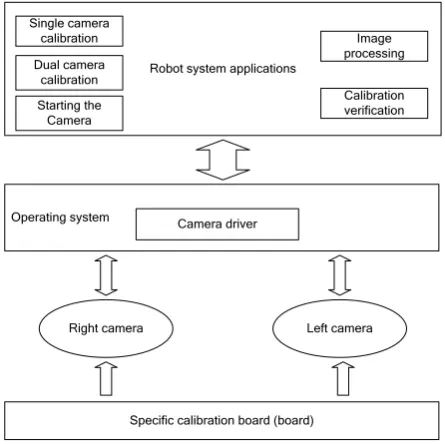
According to the design requirements, the choice of hardware and software platforms, putting the system software and hardware platforms together, to construct the overall architecture of the system shown in Fig.3.
Right camera Left camera Robot system applications
Single camera calibration
Operating system Camera driver
Specific calibration board (board) Dual camera
calibration Starting the
Camera
Image processing
Calibration verification
Fig.3 The overall structure of the robot vision system diagram
First, it needs to create specific calibration plate, placed in front of the dual cameras. Then, fixing the two cameras and to keep a certain distance between them. When performing calibration, connect the camera to the computer, drivers the camera work by operating system, camera by shooting calibration board image at different angles, and finally to the system software processing and computing. System applications collected a variety of functions, including selective access to the camera, camera calibration, image processing.
Calibration Plate
[image:3.595.194.417.210.433.2]Camera calibration using the calibration plate is not fixed, any suitable characterization of objects can be used as the calibration objects, but the fact such as that the rules of checkerboard pattern are chosen [[iv]]. After search of previous research data, pattern of flat checkerboard than three calibration objects easier to handle, so the system uses a flat checkerboard as calibration objects. In OpenCV is also based on planar objects to multiple in the field of view. Using the mode of black and white squares alternating, as shown in Fig.4, which can ensure the measurement are not offset on either side.
Fig. 4 Standard 7 × 7 checkerboard map
the view of a number of the board, and then look for the corner of each image on the chessboard, finally use multiple views all corners of image coordinates and three-dimensional to calculated the internal and external parameters of cameras.
SYSTEM SOFTWARE DESIGN Software Overview
Robot vision system software requires a high interactivity, real-time, reliability and stability. This design uses running under Windows XP system development platform Visual C + + 6.0, libraries MFC, etc., to developed a human-computer interface based on a single document.
MFC (Microsoft Foundation Class Library) is a Microsoft Foundation Class Library, encapsulates the most Win32API function, and provides an application framework, OLE support, database support, GM, etc., simplifies the development of Windows program designed to facilitate the application.
Camera calibration software design
The system intuitive embodied in the visual measurement process and displayed on the software interface. For example, all corner points on the board to be drawn and displayed in the camera calibration. Each image will get back of camera, that each frame image is continuously displayed on the software user area of the image control, so you can see effect on the video. Program using the timer to achieve video capture, video capture and display process shown in Fig.5.
Start and initialize Start
Get a frame ON timer, time ,
Timed to 30ms ,
Displayed on the picture control
Yes No
30ms the camera
Fig.5 Video capture and display program flow chart
After successful launch of the camera, firstly to get display the size of the video user area, that the size of device environment, the process is to point to the device context of the client area, then to get a device context handle, finally use Cwnd class GetClientRect () function to get the size of user area. The Timer role is use certain intervals to display the image on the picture control, when the frame rate is close to regular time, the video will be shown very smooth.
Starting the Camera Start
Get calibration image
Positioning chessboard corner
Find all corners
Drawing board corners and display
Calculation of calibration parameters
Save and display calibration results
No
Yes
Fig. 6 Single target set Program flow chart
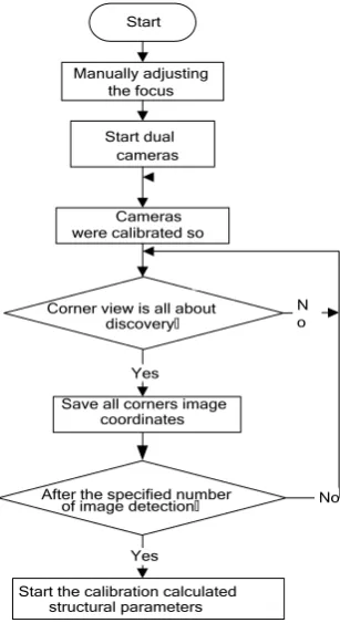
[image:5.595.228.382.432.714.2]Binocular camera calibration not only to draw the internal parameters for each camera, but also need to measure the relative position between the two cameras through calibration, namely the right camera relative to the three-dimensional translation and rotation parameters of the camera left. In OpenCV, the parameters of T and R to be calculated by function cvStereoCalibrate ().The software binocular calibration implementation process as shown in Fig.7.
Start
Manually adjusting
Cameras
Corner view is all about discovery,
Save all corners image
After the specified number
Start the calibration calculated Yes
Yes the focus
Start dual cameras
were calibrated so
coordinates
of image detection,
structural parameters
N o
No
Fig.7 Double target set Program flow chart
parameters of the camera, and calibrat the average obtained repeatedly. After calculating the internal and external parameters of each camera, we can find the parameters R and T according to the above relation.
SYSTEM TEST Single objective test set
Firstly the system must perform a single target set, the system calibrats the left and right camera namely. Clicking on the "single target set" button before, you need to enter the information of calibrated parameter. The chessboard distance, each row and column number of corner points should be consistent with the actual calibrated information, In the process of single target, the more the number of calibration board images (two images or more), the calibration results would be more accurate. In addition, each calibrated board image and the angles of camera imaging plane should be large possibly, so it can improve the precision of calibration results. Because the angle of the board needs to be changed the board angle, the system calibrates each checkerboard image every 1s. Fig.8 shows the calibration process of calibration diagram which was complete.
Fig.8 A total of 25 times the calibration chart
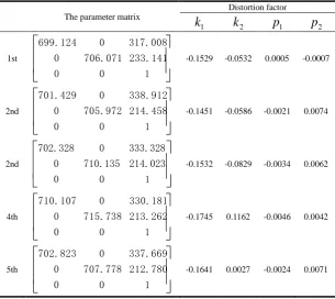
Table 1 the left of the camera calibration parameters
The parameter matrix
Distortion factor
1
k
k
2p
1p
21st
1 0 0 233.141 706.071 0 317.008 0 699.124-0.1529 -0.0532 0.0005 -0.0007
2nd
1 0 0 214.458 705.972 0 338.912 0 701.429-0.1451 -0.0586 -0.0021 0.0074
2nd
702.328 0 333.328
0 710.135 214.023
0 0 1
-0.1532 -0.0829 -0.0034 0.0062
4th
1 0 0 213.262 715.738 0 330.181 0 710.107-0.1745 0.1162 -0.0046 0.0042
5th
1 0 0 212.780 707.778 0 337.669 0 702.823 [image:7.595.156.457.389.565.2]-0.1641 0.0027 -0.0024 0.0071
Table 2 the right of the camera calibration parameters
The parameter matrix
Distortion factor
1
k
k
2p
1p
21st
1 0 0 223.894 703.666 0 317.533 0 698.814-0.1671 0.0179 -0.0049 0.0022
2nd
1 0 0 221.771 714.291 0 317.066 0 708.360-0.2082 0.2268 -0.0047 0.0026
3rd
1 0 0 230.476 709.892 0 328.631 0 706.033-0.1821 0.0945 -0.0000 0.0055
Continued Table 2 the right of the camera calibration parameters
The parameter matrix
Distortion factor
1
k
k
2p
1p
24th
1 0 0 213.262 715.738 0 330.181 0 710.107-0.1745 0.1162 -0.0046 0.0042
5th
1 0 0 212.780 707.778 0 337.669 0 702.823-0.1641 0.0027 -0.0024 0.0071
binocular calibration test
The plate of chessboard calibration is placed closer to the two camera positions (the visual area of dual camera), Then you start the camera to get image, Performing binocular calibration to calculate the structural parameters R and t between camera, it obtain rotation matrix R and translation vector t between the two cameras with the cvStereoCalibrate() which come from OpenCV.
After starting the camera calibration board, you held the board in the viewable area of camera, it can start to calibrate binocular with clicking on the "execute binocular calibration". Because of the influence of external light, it may appear some situation sometimes where a frame which return at the same time can’t find all corners, you should determine that it can find the corner of two views or not before saving the two coordinates of image views in the program. Then it only save the coordinates of corner whit two coordinates found at the same time. The calibration process is shown in Fig.9
Fig.9 binocular calibration chart
25 images be calibrated in each left and right views , At last, it put the parameters and distortion which were obtained from the camera around a single objective and the corner coordinates of left and right views about the camera double target as the input parameters of cvStereoCalibrate (),Calculating the rotation matrix R and translation matrix t which contact about cameras, The results of binocular calibration is shown in Formula 1,we can see the qualitative of double target become better than single calibration target from Formula 1.
9712
.
0
0004
.
0
2382
.
0
0388
.
0
9894
.
0
1399
.
0
2351
.
0
1451
.
0
9610
.
0
R
,t
16
.
6983
1
.
4975
5
.
0276
(1)CONCLUSION
Designed to take advantage of Microsoft's MFC library can develop powerful Windows application. OpenCV vision algorithms will function as the core of the system, combined with VC + MFC aids and basic library functions 6.0, making the system software is simple, fast, reliable, good stability, portability and other functions. Powerful images and matrix operations and ability to provide excellent OpenCV algorithms have overcome the complex mathematical calculations, making the system calibration function has been greatly guarantee.
Acknowledgements
The authors are highly thankful for the Guangxi Natural Science Foundation(ID: 2013GXNSFBA019282) ,Guangxi university research projects (ID: 2013YB205), Hechi College special projects (2003ZX-N003),Chinese College Students' Innovative Entrepreneurship Training Program(ID: 201310605008, 201310605009,201310605010)and Guangxi Students Projects of Innovation and Entrepreneurship Training Program (ID: 1100,1101,1109,1110,1111).
REFERENCES
[1]Seidel PA, Boehnke K: Research and Education in Robotics: Eurobot 2009. Edited by Gottscheber A, Obdrzalek D, Schmidt C, vol. 82; 2010: 144-157.
[2]Peng H, Zou X, Xiong J, Wu D, Shen J, She Z: Frontiers of Advanced Materials and Engineering Technology, Pts 1-3. Edited by Chen R, Sun D, Sung WP, vol. 430-432; 2012: 1963-1966.
Edited by Zhang H, Jin D, Zhao XJ, vol. 675; 2013: 72-76.
[4]Benjamin DP, Funk C, Lyons D: Multisensor, Multisource Information Fusion: Architectures, Algorithms, and Applications 2013. Edited by Braun JJ, vol. 8756; 2013.
[5]Vaughan B, Han JG, Gilmartin E, Campbell N: Acta Polytechnica Hungarica 2012, 9(1):7-17. [6]Quintian Pardo H, Calvo Rolle JL, Fontenla Romero O: Dyna-Colombia 2012, 79(175):24-33.
[7]Peng Jiansheng, Li Xing, Qin Zhiqiang, Li wei. Journal of Digital Information Management, 2012,10:277-283.
[8]Chen M, Cai Z, Wang Y, Ieee: 2012 10th Ieee International Conference on Industrial Informatics. 2012: 94-98. [9]Zhang Yujin, Image Analysis[M], Beijing: Tsinghua University Press, 2005.