The Study of Rolling Temperature Condition Influence on
the Formation of Hot Strip Cross-Section Rolled on the
Longitudinal - Wedge Mill
Mashekov S.A.
1, Mashekova A.S
2,*, Smailova G.A
1, Bekmukhanbetova Sh.A.
11Kazakh National Technical University named after K.I. Satpayev. Department of Machine Tool Technology, Material Science and
Mechanical Facilities Technology, Almaty city, 050000, Republic of Kazakhstan
2Nazarbayev University, School of Engineering, Mechanical Engineering Department. Astana city, 010000, Republic of Kazakhstan
*Corresponding Author:[email protected]
Copyright © 2014 Horizon Research publishingall rights reserved.
Abstract
The mill of new construction is proposed in the article. To calculate the specialized metal forming processes the software of finite element analysis - MSC Super Forge MSC Visual Nastran 4D was used. Stress-strain state (SSS) of the rolled workpiece and heavy-loaded units of the proposed mill was calculated. The influence of the rolling temperature regimes on formation of hot-rolled strips cross-section was investigated. The hot-rolled strips were rolled on longitudinal wedge mill. It is proved that the workpiece is deformed in the conditions of “soft” SSS in a mill of new construction, in other words the amount of the elastic deformation and displacement of the rolls units are small. The investigation has also proved sufficiently high fixity of the joints of roller assembly work stand as well as that the equivalent voltage does not exceed the maximum permissible value for the material strength in heavy-loaded units of the mill.Keywords
Rolling, Temperature Conditions, Longitudinal-Wedge Mill, Hot-Work Strips1. Introduction
In recent decades, requirements on the tolerances of the hot-rolled strip cross-section are decreased in the world production, owing to the general trend of increasing quality requirements for sheet metal [1]. This is true for most thin hot strips with a thickness of 0.8 - 1.5 mm directly used in mechanical engineering and construction, and for strips with a thickness of 1.8 - 3.0 mm, sent as a tackle on the cold rolling mills in order to produce from them automotive sheet or other product mix with stringent requirements for flatness and surface conditions [2, 3, 4, 5].
It should be noted that to regulate transverse and longitudinal crown and flatness of the rolled strips it is required to advance the power parameters and heat
treatment of the rolling, hot rolling mill rolls, the elastic profile and grinding profiling rolls. Thus in order to reduce deviation of standardized characteristics of hot-rolled strips cross-section (lateral variation in thickness, taper, local variations of thickness, vertex off set) up to values defined by the tighter tolerance sit is necessary to influence on the aforementioned factors affecting the accuracy of the formation of the cross-section [6,7,8,9,10].
Some modeling aspects of the elastic flattening and thermal regime of strips and hot rolling mill rolls were published in the last 15-20 years [6,7,8,9], however a comprehensive study which allows to calculate the geometric parameters of rolled sheets depending on the technological parameters of the rolling process and control actions is absent so far. The absent of such research is due to the complexity of the problem and the need to carry out industrial research on a large, high-performance steel equipment where very little prospects for scientific experiments.
Thus, improvement of power parameters, as well as the thermal regime of rolling strip and cooling rolls systems of hot rolling mills is an actual task not only for the hot rolling mill plants, but also for the whole flat rolled products manufacturing [10]. Effective solution to this problem is possible on the basis of the improvement of rolling equipment and roller systems, the development of automatic control systems in thickness, profile and flatness of rolled bands, creating new ways of rolling and roller systems for their implementation.
In our opinion, the best method to control cross gage interference and flatness is the optimization of the drafting schedule and the efforts of hot rolling. To this end, a design of rolling mill was developed [11], which allows assigning rational technological parameters of rolling.
2. Equipment, Materials and
Methodology of the Research
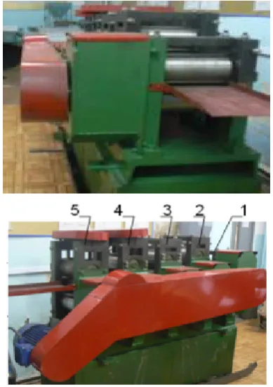
Rolling of the strips was made on the newly designed longitudinal-wedge mill (Figure 1) [11].The longitudinal-wedge mill for rolling strips from steel and alloy contains the workstand, electric motor, clutch, bearing non-driven rollers, workers drive rollers, base frame, a support plate. The cage, that have AC motor drive, comprises working and supporting rolls with constant diameter, whereas in consequent located cages the diameter of working rolls decreases, and the diameter of the supporting rolls increases in the rolling direction. In this case, the rotation of the rolls is carried out through individual clutch gear box, gear set, pinion stand and spindles, whereas the diameters of the work and backup rolls are determined by the formula, respectively:
(
)
)
1
(
1
1 1 1 1 + + + ++
+
⋅
⋅
⋅
=
i i i i i i ii
h
h
D
n
n
s
s
D
;(
)
(
1)
1 1 1
1
1
− − − −+
+
⋅
⋅
⋅
=
j j j j j j j js
s
n
h
n
D
h
D
; (i = 1, 2, …, N; j = N,…2, 1),where hi, hj = the thickness of the rolledstrip in ior jmill stand;
niand nj=frequency of rotation of the rollers ior jmill stand; N = serial number of the mill stand;
siand sj = forward slip on the output from ior jmill stand rolls.
[image:2.595.81.276.432.708.2]1, 2, 3 - four-rolls workstands without pressure device; 4,5 - four-rolls workstands with pressure device.
Figure 1. Five-workstands longitudinal wedge mill
Inthe proposed mill horizontal axis of upper and lower rollers of the first three mill stands without pressing mechanism is shifted from the rolling axis in the vertical direction by the amount of
0
,
25
2i pi n
i
k
D
x
=
⋅
⋅
⋅
α
∆
where Dpi = diameter of new work rolls of i mill stand, mm;
kп = coefficient of regrind;
αi = permissible angle of capture for rolls of i mill stand. It should be noted that the predetermined distance between the work rolls from one stand to another increases the amount of forward slip.
In order to conduct a comprehensive research computer simulation of the industrial rolling mill of the proposed construction was carried out.
Computer simulation of the rolling process was the study of the stress-strain state (SSS) of rolled sheet and separate heavy-duty elements of mill stands. It is complicated process because of the large number of defining parameters and ambiguous nature of their influence [12]. The correct formulation of the problem, even for simple rolling, leads to a system of integral-differential equations, which is not possible to solve analytically. However, currently for such tasks is widely used finite element method implemented in the software products of finite-element analysis [12]. One of the software products of finite element (FE) analysis, which specialized in calculation of metal forming processes, are MSC Super Forge and MSC Visual Nastran 4D. The accuracy of the calculations and the effectiveness of the above software products for computer simulation of rolling confirm the experience of the leading industrial companies in Japan, the U.S. and the EU, such as Ford, BMW, Toyota Motor Co, DENSO, etc.
The task of the massive SSS study of relatively thick plate during the rolling is contact, elasto-plastic and nonlinear, taking into account temperature regime deformation, and large displacements and deformations. For these purposes FE software was applied to analyze nonlinear, non-stationary metal forming processes. Calculations were carried out in a volume setting including the temperature field.
A three-dimensional geometric model of a relatively thick sheet was built in the CAD program Inventor, and imported into the CAE program MSC Super Forge. During the creation a finite element model of a thin slab three-dimensional volume element CTETRA (quadrangular tetrahedron) was used for modeling three-dimensional bodies.
The technical characteristics of work stands of the proposed and enlarged laboratory mill were used in order to calculate the SSS. Semi-finished rolled stock with a thickness h0 = 5 мм was used for hot 1,0×200 mm strip
rolling at 1200°C in the continuous five stands mill.
simplification will allow to simulate the rolling process at steady state without a large computational cost. Calculation time of the rolling process in each stand was 30 minutes on a computer Pentium Duo with a time frequency of 3.4 GHz and 2 GB of RAM.
In MSC Super Forge tools made absolutely rigid and provide only the properties of the thermal conductivity and heat transfer, in other words the thermal conductivity, specific heat and density are taken into consideration, and mechanical properties are ignored. SH15 was assigned from a database of materials as a tool material. Density and thermal properties for this material was assigned by default by the program.
The interaction between the hard roll and deformable material of the workpiece is modeled by the contact surfaces, which describe the contact conditions between the surfaces of rolls and the surface of a relatively thick sheet. The modeling contact conditions are constantly updated to reflect the rotation of the rollers and the deformation of a material that allows simulating sliding between the roll and the material of the workpiece. The contact between the roller and the thick sheet was modeled by Coulomb friction, the friction coefficient was 0,3. S20C material was assigned from the material database (According to the standards of CIS countries S20C corresponds to St08kp). The chemical composition of the steel SHKH15 and S20C is presented in the handbook [13].
Temperature regime during the rolling is composed of a heat exchange between the roll, a thin slab and the environment, as well as the effect of heat due to deformation of the metal. Rolling process takes place at room temperature, so the initial temperature of the roll was set to 200С.
Working stand of the proposed mill is a multi-machine including spinning mill rolls, bearings, base frame, mounting mechanisms of rolls, fastening devices and other components and spare parts. The construction of such a machine is very complex and time-consuming process that requires a large amount of calculation and graphic works.
Given the above, the method of calculation implemented using the program of finite element analysis MSC Visual Nastran4D. Computer simulation system MSC Visual Nastran 4D allows to explore the kinematics, dynamics, mechanisms with the possibility of stress-strain and thermal conditions, as individual units, and the mechanism as a whole.
The following operations were made during the design of the work stand mills in MSC Visual Nastran 4D:
creation a geometric model of each part and assembly units of working stand mills;
selection of material for items and their mechanical and physical properties (modulus of elasticity, mass density, Poisson's ratio, tensile strength, etc.);
formation of kinematic and static boundary conditions;
creation of the detail finite element mesh;
determination of the stress-strain state;
assessment of the level of obtained elastic strains and stresses in the volume of each part relatively of the required stiffness and strength criteria and the introduction of appropriate changes in the design of the mill (solid model of the machine).
The initial data for the calculation are the solid-state geometry of the mill construction, strength and these curing conditions attached to them, and the terms of the kinematic coupling pairs of the design stand mills.
3D geometric model of the assembling camp was built in the CAD program Inventor, and by the built-in translator and with accepted kinematic constraints it was imported into the MSC Visual Nastran 4D environment. This approach allows improving the communication stage of the automatic design of complex mechanisms.
The method of geometric dimensions parameterization of the structure was used in order to enable automatic adjustment of geometry model of the roll. This method allows making appropriate modifications to the instrument based on the calculation results of the elastic flattening and bending rolls.
In a preliminary analysis of the mill, based on the symmetry condition of the design elements, as well as to simplify the design scheme, the most power-laden components such as rollers, chromed, crates and neck rolls were taken to the calculation. The collision and friction in the rolls and stand mills were taking into account in the calculations.
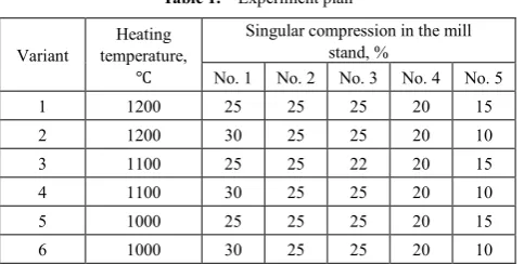
[image:3.595.313.555.631.753.2]For laboratory experiments the strip with a length of 200 mm and with a cross-section of 5 × 200 mm from steel 08kp was used. The strips were performed by electrical discharge cutting from hot-rolled sheet in the delivery condition. These strips were heated in a furnace with the velocity 20℃/min up to temperatures shown in Table 1, and were kept for 30 min. During the experiment the compression modes and rolling temperature were varied (Table 1). After heating and during the rolling process the temperature was measured by fast and reliable thermocouple probes (type K thermocouple probe (NiCr-Ni)) of a single-channel instrument for measuring temperature Testo 925 (Testo AG, Germany). Measured temperature range was from 50 to +1200℃. Error: 40...+900℃ - ± 0,5℃+0,3% from the measured value; - + 900…+1200℃ - ±0,7℃+0,5% from the measured value. Resolution: 0,1℃ (-50 till +199,9℃), 1℃ (in the rest measurement range).
Table 1. Experiment plan
Variant temperature, Heating
℃
Singular compression in the mill stand, %
No. 1 No. 2 No. 3 No. 4 No. 5
1 1200 25 25 25 20 15
2 1200 30 25 25 20 10
3 1100 25 25 22 20 15
4 1100 30 25 25 20 10
5 1000 25 25 25 20 15
In the laboratory conditions the strip flatness defects and variation in thickness were measured at the free sheet location on the plane of control table by iron ruler, indicator, caliper and micrometer with dial plate. The geometrical dimensions of the workpiece were measured by caliper and micrometer.
3. Results and Discussion
Rolling process in the proposed mill can be divided into four stages. Therefore, for visualization of the calculated
data the four stage percentage of the total deformation time were taken, thus the following intervals have been chosen: the first stage 20, the second stage 40, the third stage 60, and the fourth stage 80 percent of full-time deformation.
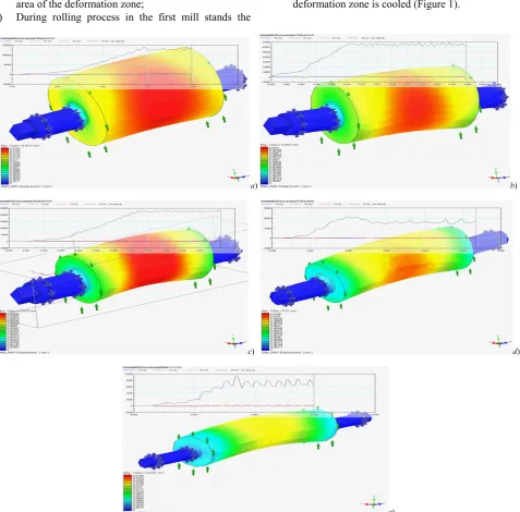
The distribution pattern of the temperature field in a thin slab rolling in the stands of a new mill is presented in Figure 2 (due to the large volume the stress-strain state and the rolling forces are not shown). Actual temperature values are given in the digital form on the respective color diagrams.
а) b)
c) d)
e)
[image:4.595.60.549.224.697.2]а – stand mill 1; b – stand mill 2; c – stand mill 3; d – stand mill 4; e–stand mill 5
Based on the obtained results of numerical simulations it is found:
1) Efforts ofhot rolling, resulting in a new mill stands are greatly reduced (from 2 to 10 times) in the rolling direction when processing in a new mill (Figure 3); 2) During the rolling process in the first mill stands at a
strain (ε) and at a stress (σi) the initial moment of the rolling focuses on the zones of capturing metal by the mill rolls. With increasing compression of ε and σitransferred from the surface to the center and the edges of the deformable piece. Further increasing the compression results in a more uniform distribution of ε and σiin the central zone of the workpiece, and at the end the intensity passage of the strains and stresses are concentrated in the center of the entrance area of the deformation zone;
3) During rolling process in the first mill stands the
temperature decreases in the contact areas "hot metal-rolls". In later stages of rolling through the heat forming and friction, the temperature at the center of deformation aligned (Figure 2). However, in the end of the passage the portions of the workpiece being in the output of the deformation cools sharply;
4) When rolling in the second, third, fourth and fifth mill stands zones of intense concentration of ε and σiin the process of rolling mixed up gradually from the center to the peripheral zone of the deformation; 5) When rolling in the second, third, fourth and fifth
mill stands the high temperature zones is moving together with the deformation zone from the start till the end of the passage. In this case, the contact area of deformable metal roller and the area outside the deformation zone is cooled (Figure 1).
а) b)
c) d)
[image:5.595.68.546.259.729.2]e)
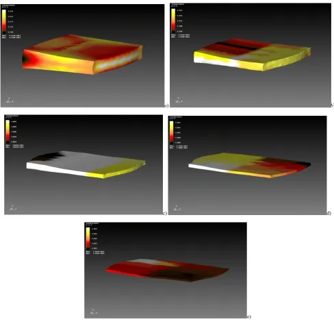
Figure 3 shows the pattern of the total displacement distribution (elastic flattening and bending rolls) of the rolls during the rolling of billet with the above non-uniform temperature field at the new mill.
Conducted calculations of the finite-element models showed that:
- picture of the distribution of total movements in three directions consistent with the deformed shape of the rolls. The maximum value of displacement is 0.0178mm observed in the middle of the rolls;
- under the influence of applied vertical forces the rolls bend in the direction of force, and the roll neck is elastically deformed in the same direction, the maximum value for the elastic deformation of roll barrel is 0.00008 and to roll neck is 0.00044;
- voltage in the rolls body varies in the range from 0 to 1.1 e+8Pa, and the maximum stress occurs in the roll neck. The maximum gained value of effective stress is 1,1е+8 Pа, which does not exceed the maximum permissible value for the strength of the material 1.380e +9Pa;
- rolling in the last stands of the proposed mill, especially in unsteady phase of the rolling, the resonance vibration increases which are accompanied by vibrations of the rolled strip in the last interstand intervals (Figure 3). The growth time of the vibration of amplitude in non-stationary phase is equal to 1 – 2 s. However, at the steady stage the rolling process is stabilized, which prevents breakage of the strip and increases the accuracy of the produced strip.
In general, the amount of elastic deformation, and moving elements of the rolls is low, which indicates a high rigidity of the work stand roller assembly. This guarantees a lateral variation in thickness and flatness of the rolled strips within the required tolerances.
It can be concluded that the compensation of the workers rolls movement in the last stands of the new mill can be accomplished by increasing the convexity of the work rolls at each new filling. In this case, the work rolls should be prepared with profiling 0.03 - 0.05 mm.
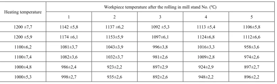
Research results of the temperature distribution after rolling in every mill stand presented in the Table 2, which
shows that the temperature of the strip dropped during the transition from one stand mill to another one.
Comparison of the theoretical results and experiment research showed their good correspondence. For the temperatures of the surface band of the rolled strips relative difference of the results does not exceed 10%.
Comparing the theoretical results and the results of experimental research it is necessary to take into account that stochastic causes, such as inhomogeneity of the structure and mechanical properties of the strips, reality of structure and characteristic of the mechanical properties of strips metal under the action of working degree, inaccuracy of the compression during the rolling process, can influence on the accuracy of the obtained results.
The results of experimental research show that the temperature of the strip increases due to heat of forming and friction caused by the increased speed of rolling in the last mill stands of the mill.
The analysis of cross-sectional gage interference of rolled strips showed that their value for strips with width of 1.4 mm deviates from 0.025 to 0.035 mm. The average value of the cross-sectional gage interference of hot-rolled strips is 0,03 mm. In this case, the minimum value of gage interference have those strips which are rolled at 1200 ° C with a small compression in the final stand. The gage interference of the strips increases with increasing compression in the final stands and decreasing temperature.
Cross-sectional gage interference of hot-rolled strips, rolled on the examine mill, satisfies the requirements of the standards for 100% of the strip’s length, except end sections (96%).
Statistical research of the rolled strips flatness for proposed continuous mill showed that the average value of flatness defects amplitude is 2.2 - 3.2 mm, thereby the flatness decreases as the temperature of the rolled strips increases.
[image:6.595.64.550.601.748.2]Thus, the use of new semi-industrial mill of hot rolling allows decreasing cross-sectional gage interference and therefore to increase operational efficiency of the automatic control system of the strips gauge or without any automatic control system the strips of the high quality can be rolled.
Table 2. Temperature condition of experiment rolling
Heating temperature Workpiece temperature after the rolling in mill stand No. (℃)
1 2 3 4 5
1200 ±7,7 1142 ±5,8 1137 ±6,2 1092 ±5,3 1113 ±5,4 1106±5,8
1200 ±5,9 1174 ±6,1 1153±5,9 1097±6,1 1124±6,8 1112±6,6
1100±6,2 1081±3,7 1043±3,9 996±3,8 1016±3,3 958±3,6
1100±7,4 1082±3,6 1032±3,7 981±2,6 1009±2,8 974±2,6
1000±4,8 986±2,4 923±2,2 897±2,9 924±2,9 897±2,7
4. Conclusion
1. The analysis of the results of theoretical and
experimental research shows
satisfactory convergence of their results and confirms the principal possibility of using MSC.SuperForge software for theoretical calculations of SSS;
2. To control the gage and flatness interference, as well as to reduce the effort of rolling from one mill stand to another in the rolling direction a construction of new longitudinal wedge rolling mill has been designed;
3. Roll bending simulation proved that the elastic deflection of rollers is decreased by reducing the pressure of rolling when the thin strips rolled on a new mill and consequently, cross-sectional gage interference of rolled strips decreases and the flatness of rolled strips improves;
4. Quantitative data was obtained and fundamental relationships of SSS change during rolling process in the longitude wedge mill were set;
5. Rolling of thin strips on the new semi-industrial mill was conducted and obtained that the use of the new mill of hot rolling allows to decrease cross-sectional gage interference of the strips.
REFERENCES
[1] Antipin V.G..Advances in the production of thin steel strips. // Мoscow: «Ferrous metallurgy information» JSC. Statement«Metallurgy offerrous metals», 2002, No.8,p. 3-9. [2] Maksimov E.A. Improvement of the strip flatness. //
National metallurgy. Equipment. 2005, No. 1, p. 22-27. [3] G. Boulton, T. Domanti, T. Gerber, G. Wallace. Strip edge
shape control. Achieving profile & Flatness in Flat Products. IOM Conference, Birmingham. January 2006, pp. 57–64. [4] Maksimov E.A. The use of the rolling mill stands with the
adjustable roll gap profile. // National metallurgy. Equipment. 2006, No. 11, p. 46-49.
[5] Maksimov E.A. The exploring of new mechanism to reduce pressure and improve compressions at asymmetrical rolling / / Metalworking. - 2010- № 1 - p. 46-49.
[6] Maksimov E.A. Quality improvementand strips flatness enhancement from corrosion resistance steel during self-control process of asymmetric rolling. // Metal technology. 2010, No. 9, p. 19-24.
[7] V.E. Lunev, I.G. Shubin, M.I. Rumyantsev and others. The management of roughness of feeds by asymmetric rolling / / Production of steel. - 2003. - No. 6. - p. 28-29.
[8] Maksimov E.A. The flatness of sheet metal. The between deformational and new kinematic criteria of flatness of strips during the rolling / / National Metallurgy. Equipment. - 2006. - № 9. - p. 45-51.
[9] Ju.Sidorov, A.Miroux, R.Petrov, L.Kestens. Microstructural and crystallographic aspects of conventional and asymmetric rolling processes // Acta materials. - 2008. - 56, № 11. - p. 2495-2507.
[10] Agheyev L.M. The managing impacts on the shape of the strip in the rolling / / Proceedings of 4th Congress of Rollermen, Magnitogorsk, 16-19 October, 2001. Vol.1. - Moscow, 2002. - p. 192-197.
[11] S.А. Mashekov, E.Z. Nugman, А.S. Mashekova, etc. A continuous strip rolling mill for steel and alloy. PatentNo. 20969.//Published. 16.03.2009.Statement №3.
[12] Ivanov K.M., Shevchenko V.S., Yurgenson E.E. The Finite Element Method in the technological problems of metal forming. Text edition. Saint Petersburg: MechanicalEngineeringInstitute, 2000. p. 217.