ISSN: 1992-8645 www.jatit.org E-ISSN: 1817-3195
4X4 CIRCULAR PATCH PHASED ARRAY FOR AIRBORNE
APPLICATIONS
1
U.SRINIVASA RAO, 2P.SIDDAIAH
1
Associate Professor, Vignan’s Lara Institute of Technology & Science, Guntur, Andhra Pradesh, India
2
Acharya Nagarjuna University (ANU), Guntur, Andhra Pradesh, India
E-mail: [email protected], [email protected]
ABSTRACT
This paper concentrates on design, modeling, simulation and performance analysis of a Microstrip Line Quarter Wave Transformer-fed 4x4 Circular Patch phased array. The substrate material RTDuorid5880 used for this has thickness of 1.588mm and relative permittivity (εr) is 2.2. The design frequency is 2GHz and VSWR ≤ 2. The proposed 4x4 Circular Patch phased array is modeled and simulated by using ANSOFT HFSS 15.0. The gain of this array is 16.963 dB with return loss of -24.91dB. The phased array is steered for 100, 200, 300, 420 and 450 with a bandwidth of 31.9 MHz. This proposed Phased array is very useful for L band airborne applications such as satellite navigation, mobile wireless communication, radar and telemetry, tracking, and command (TTC) for mini satellites.
Keywords: Quarter Wave Transformer, RTDuorid5880, Circular Patch, Return Loss.
1. INTRODUCTION
In recent Years, the phased array antenna technology an emerging technology day to day, there has been an increasing demand for high gain and narrow beam antennas in the fields of communication as well as the radar. The high gain is used for long distance communication and the narrow beam is useful for finding the direction of the system. The beam scanning or steering is needed to search the object or target in a given volume of the space.
These general limitations with the mechanical scanning. In mechanical scanning, the entire antenna system should be mechanically rotated to steer the beam form one position to another. A
practical limitation encountered with the
mechanical inertia of the antenna and angular accelerations in re positioning beam, these gives rise to distortion in the radiation.
To overcome these limitations one has to go for electronic scanning for electronic beam scanning in which no mechanical inertia is involved. The method of positioning an electromagnetic beam in space by electric means with the antenna aperture physically remaining fixed is called electronic scanning or electronic beam steering.
There is a need for beam steering to perform different function modes of an aircraft like ground
mapping for navigation, search and track of ground and air targets.
Phased array antennas with beam steering capability attractive not only sophisticated applications but also in terms of low power consumption in radar and wireless communication application. In electronic beam steering the signal is transmitted in the desired direction hence there is no interference.
2. LITERATURE SURVEY
Microstrip antennas are one of the most popular geometries because they are light weight occupies less volume, inexpensive to fabricate and can be easily made conformal to the host body like air craft, space craft, missiles and satellites.. The attractive features of the microstrip enhanced their application in the recent past and stimulated an ever increasing attention from all around to investigate their performance further. Of all the shapes of the microstrip radiator the circular patch tends to be smaller than other configurations. In some applications, such as arrays, circular geometries provide certain advantages over others, since the feed can be connected at any point along the periphery of the circular microstrip. The circular patch is matched to 50Ω feed line via quarter wave transformer [1-3].
ISSN: 1992-8645 www.jatit.org E-ISSN: 1817-3195 Radiators,. In this paper, it was shown practical
circular patch radiators may exhibit usual scanning properties in a planar phased array configuration. In this paper it is concluded that small array provides reliable results for scanning angles greater than 600
off broadside. The principal method of
investigation is the small array using 8x8 element, but two waveguide simulators were used to check the results.
Frank W. CIPOLLA [5] was investigated on A 7.5 GHz Microstrip Phased for Aircraft for aircraft-to-Satellite communication. In this paper, the maximum size of the proposed antenna array of 8x8 rectangular lattice is 17.9x16.3 cm. the gain of the proposed antenna is 20dBic and bandwidth 500MHz. the beam is steered to 600 when the spacing between the elements is 0.51λ and it is steered to 450 when the spacing between the elements is 0.56λ.
Greg Zomchek, Sharad laxpati [6] presented on s-band phased array for satellite applications. A microstrip Wilkinson splitter followed by a quearter wave transformer was designed and integrated with dual feed square patch in HFASS to provide LHCP Centered at 2.78GHz resulting in an 8.7% bandwidth and the beamwidth is steered in ±120. An s-band phased array was designed for communication between a satellite in geostationary orbit and spacecraft in lower earth orbit.
A research paper on Design and analysis of high gain millimeter wave microstrip antenna array for wireless applications by K. Shambavi, Zachariah C Alex, T. Naveen Phani Krishna[7]. A tranmisssion line model is used to design antenna array and simulated using IE3d software. The proposed antenna array of 8x8 able to gice a maximum gain of 18.48 dB and beamwidth of 10.490.
A research paper, presented by P. Sai Vinay Kumar, P. Jagadamba, M.N. Giri Prasad [8] on a phased antenna arrays of 4x4 square grid with circular patch for radar applications designed at 1.35 GHz frequency. The antenna array simulations are carried out by using HFSS software. In this paper the proposed phased antenna steered ±100 in elevation direction and are useful for many types of
applications such as Satellite navigation,
Telecommunications, Aircraft surveillance,
Amateur radio, Digital Audio Broadcasting and Astronomy.
The main aim of the proposed QWT Fed 4X4 array antenna is to get the high gain, high directivity, high efficiency, narrow beamwidth and
to enhance the beam steering capability from 00 to 450 in elevation direction.
3. DESIGN OF PROPOSED CIRCULAR
PATCH ANTENNA
The design of the circular microstrip patch array begins with single element. The circular microstrip patch antenna design can be divided into three stages, namely design of the circular patch, the quarter wave transformer and the microstrip feed line. Each of these stages is presented in detail below.
2.1 Design of Circular Patch
Radius of the patch:
The radius 'R' of the circular patch can be found from the following equation [3]:
R = radius of the patch in mm;
h = height of the patch substrate in mm;
fr = resonant frequency in Hz;
εr = effective dielectric constant of the substrate.
Using the above expression the calculated radius is 28.52 mm for 2 GHz operating frequency, with RTDuorid5880 substrate having dielectric constant of 2.2 and height of the substrate is 1.588 mm.
2.2 Design of the Quarter wave Transformer
Impedance matching is an important aspect in the design of microwave and millimeter circuitry since impedance mismatch may severally deteriorate the
overall performance of electronic system.
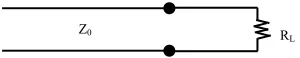
Impedance matching is necessary for the best possible energy transfer from stage to stage. Consider a transmission line with characteristic impedance Zo with a resistive load RL as shown in
Figure 1. If Zo = RL then the maximum power
[image:2.612.349.499.641.670.2]delivered to the load.
Figure 1: Transmission Terminated with Resistive Load
If Zo ≠ RL, then we have to use a matching
network in the transmission line. There are different methods to match the source impedance
Z0 R
ISSN: 1992-8645 www.jatit.org E-ISSN: 1817-3195 with the load. They are L Network, single stub
[image:3.612.106.289.184.260.2]tuners and quarter wave transformers. A Quarter Wave Transformer (QWT) whose length is ¼ of wave length is a simple and useful device for matching real load impedance to source impedance as shown in Figure 2.
Figure 2: Transmission Line with Matching Network (QWT)
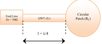
[image:3.612.110.283.312.387.2]Similarly we can design microstrip line QWT to match 50Ω line and the circular patch as shown in Figure 3.
Figure 3: Circular Patch Matched with Feed Line Via QWT Microstrip Line
The input impedance of the QWT is geometric average of the Zo and RL. [11]
(2)
Where
Z0 = Characteristic Impedance of the Feed Line = 50Ω
RL = Input impedance of the circular patch = 340Ω
From the above values the calculated impedance of QWT is 130Ω.
2.3 Design of a Microstrip line feed
To excite the circular microstrip patch, a 50Ω microstrip line is used. The widths of the QWT & microstrip line calculated with the known values ZT=130Ω, Zo=50Ω and dielectric constant of the
substrate εr (2.2) using the standard equations is
given below [12].
The calculated widths of 50Ω microstrip line and QWT is 4mm and 0.7mm respectively
Dimensions of proposed single circular patch antenna is given in Table 1
TABLE 1: Calculated Dimensions of Proposed Single CPA
Parameter Value(mm)
Radius of CPA (R) 28.52
Height of the substrate (h) 1.588
Length of the substrate (Ls) 138.52
Width of the substrate (Ws) 60
Length of QWT (Ltr) 28.62
Width of the QWT (Wtr) 0.74
Length of the feed line (Lf) 10
Width of the feed line (Wf) 4
[image:3.612.324.526.343.510.2]The geometry of the proposed circular patch antenna fed with QWT is shown in Figure 4.
Figure 4: Geometry of the Circular Patch Antenna
The modeled structure of single circular patch antenna is as shown in Figure 5 with a maximum size of antenna as 200mmX350mmX24mm.
Figure 5: Structure of Modeled Single Circular Patch Antenna.
Feed Line
Zo = 50Ω QWT (ZT)
Circular Patch (RL)
l = λ/4
Z0 R
L
ISSN: 1992-8645 www.jatit.org E-ISSN: 1817-3195
4. DESIGN AND ANALYSIS OF 4X4
CIRCULAR PATCH PHASED ARRAY ANTENNA
The array factor for N elements in general is [10]
(6)
Where
The direction of the major radiation from an array can be controlled by changing the phase excitation between the elements. It is then logical to assume that the maximum radiation can be oriented in any direction to form a scanning array.
The single QWT fed circular patch antenna is used as the array element for this 4x4 planar array. The spacing between elements in X-direction 100mm and Y-direction 150mm is maintained to get desired radiation characteristics. All the elements are fed with the same amplitude and difference in phase. The structure of modeled and simulated 4x4 circular patch phased array antenna is shown in Figure 6.
[image:4.612.312.528.57.212.2]
Figure 6: 4x4 Circular Patch Phased Array
5. SIMULATED RESPONSE OF 4X4
CIRCULAR PATCH PHASED ARRAY ANTENNA
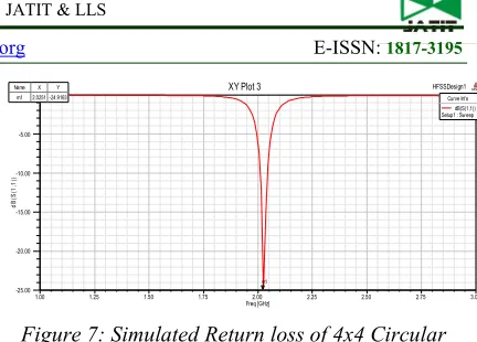
The simulated return loss, VSWR and Bandwidth of the proposed QWT Fed 4x4 Circular Patch Phased Array are as shown in Figure 7-9.
Figure 7: Simulated Return loss of 4x4 Circular Patch Phased Array
Return loss is a measure of the reflected energy from a transmitted signal. It is a logarithmic ratio measured in dB (decibel) that compares the power reflected by the antenna to the power that is fed into the antenna from the transmission line.
The larger the value of return loss the less is the energy reflected. For good impedance matching resonant frequency must lie below -10dB.
[image:4.612.317.538.376.484.2]The obtained return loss of the proposed QWT Fed 4x4 Circular Patch Phased Array antenna at 2GHz is -24.91dB.
Figure 8: Simulated VSWR of 4x4 Circular Patch Phased Array
VSWR stands for Voltage Standing Wave Ratio. VSWR is a measure of matched impedance. The parameter VSWR is a measure that numerically describes how well the antenna is impedance matched to the radio or transmission line it is connected to. The smaller the VSWR the better the antenna matched to the transmission line and the more the power delivered to the antenna. For the perfect matching VSWR = 1, there is no reflection and return loss. In the real system it is very hard to achieve a perfect match, so it is defined that having VSWR < 2 is good matching system.
The obtained VSWR of the proposed QWT Fed 4x4 Circular Patch Phased Array antenna at 2GHz is 1.1872.
1.00 1.25 1.50 1.75 2.00 2.25 2.50 2.75 3.00
Freq [GHz] -25.00
-20.00 -15.00 -10.00 -5.00 0.00
d
B
(S
(1
,1
))
HFSSDesign1
XY Plot 3 ANSOFT
m1
Curve Inf o dB(S(1,1)) Setup1 : Sw eep Name X Y
m1 2.0251 -24.9163
0.92 1.00 1.50 2.00 2.50 3.00
Freq [GHz] 0.00
125.00 250.00 375.00 500.00 625.00 736.66
V
S
W
R
(1
)
HFSSDesign1
XY Plot 2 ANSOFT
MX1: 2.0239 1.1872
[image:4.612.89.306.444.628.2]ISSN: 1992-8645 www.jatit.org E-ISSN: 1817-3195
Figure 9: Simulated Bandwidth of 4x4 Circular Patch Phased Array
The Bandwidth is defined as the range of frequencies over which antenna parameters like
bandwidth, gain input impedance, VSER,
Beamwidth, VSWR and are within the specified value are called bandwidth. It is the range between upper cut-off frequency and lower cut-off frequency at -10 dB. Bandwidth indicates range of frequency for which an antenna provides satisfactory operation
The obtained Bandwidth of the proposed QWT Fed 4x4 Circular Patch Phased Array antenna at 2GHz is Bandwidth 31.9MHz.
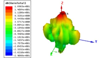
The simulated gain, directivity efficiency and half-power beam widths in both elevation and azimuth directions of the proposed QWT Fed 4x4 Circular Patch Phased Array are as shown in Figure10-14.
Figure 10: Simulated Gain of 4x4 Circular Patch Phased Array
Gain is a measure of the ability of the antenna to direct the input power into radiation in a particular direction and is measured at the peak radiation intensity. The gain of an antenna in a given direction is the amount of energy radiated in that direction compared to the energy an isotropic antenna would radiate in the same direction when driven with the same input power. The gain of the antenna is depends on the aperture size.
[image:5.612.91.521.69.198.2]The obtained gain of the proposed QWT Fed 4x4 Circular Patch Phased Array antenna at 2GHz is 16.963 dB
Figure 11: Simulated Directivity of 4x4 Circular Patch Phased Array
Directivity of an antenna is a measure of the concentration of the radiated power in a particular direction. If the antenna had 100% radiation efficiency, all directivity would be converted to gain. The directivity is depends on the radiation pattern of the antenna.
[image:5.612.101.275.452.554.2]The obtained directivity of the proposed QWT Fed 4x4 Circular Patch Phased Array antenna at 2GHz is 17.106 dB
Figure 12: Simulated Efficiency of 4x4 Circular Patch Phased Array
Efficiency is the ratio of power actually radiated to the power put into the antenna terminals. It also can be calculated as radiation resistance divided by total resistance. A high efficiency antenna has the most power present at the antenna’s input radiated away whereas a low efficiency antenna has most of the power absorbed as losses within the antenna. The losses within an antenna are usually the conduction losses and dielectric losses.
The obtained efficiency of the proposed QWT Fed 4x4 Circular Patch Phased Array antenna at 2GHz is is 98%
Figure 13: Simulated Elevation HPBW of Circular Patch Phased Array.
1.01 1.50 2.00 2.50 3.00 3.50 3.70
Freq [GHz] -35.94
-25.00 -12.50 -2.31
d
B
(S
(1
,1
))
HFSSDesign1 XY Plot 7
MX1: 2.0431 MX2: 2.0112
-10.3905 -10.3859
0.0319
Curve Info dB(S(1,1)) Setup1 : Sw eep
40.00 80.00 120.00 160.00
90 60 30 0 -30
-60
-90
-120
-150 -180
150 120
HFSSDesign1
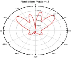
Radiation Pattern 3 ANSOFT
Curve Inf o xdb20Beamw idth(3) rETotal
ISSN: 1992-8645 www.jatit.org E-ISSN: 1817-3195 The angle between the points in the main lobe
that are down from the maximum gain by 3 dB is called Beamwidth. It is also known as the Half Power Beamwidth (HPBW) is typically defined for each of the principle planes.
[image:6.612.318.523.90.172.2]The obtained elevation half power beam width (HPBW) of the proposed QWT Fed 4x4 Circular Patch Phased Array antenna at 2GHz is 21.43570.
Figure 14: Simulated Azimuth HPBW Of Circular Patch Phased Array.
The obtained Azimuth half power beam width of the proposed QWT Fed 4x4 Circular Patch Phased Array antenna at 2GHz is 12.77560.
6. BEAM STEERING OF 4X4 CIRCULAR
PATCH PHASED ARRAY
The proposed phased array is steered at an angle of 100, 200, 300, 420 and 450 in elevation direction by changing the progressive phase between the elements.
[image:6.612.94.301.178.293.2]The phase difference between the elements in both the directions is 600, the elevation beam is steered at 100 with a Half Power Beam Width (HPBW) of 18.83740 as shown in Figure 15.
Figure 15: Simulated Elevation Beam Steered At 100.
The phase difference between the elements in both the directions is 1220 and the elevation beam is steered at 200 with a HPBW of 22.87860 as shown in Figure 16.
Figure 16: Simulated Elevation Beam Steered At 200.
[image:6.612.318.427.249.332.2]The phase difference between the elements in both the directions is 1560 and the elevation beam is steered at 300 with a HPBW of 21.66900 as shown in Figure 17.
Figure 17: Simulated Elevation Beam Steered At 300.
[image:6.612.319.430.408.505.2]The phase difference between the elements in both the directions is 1780 and the elevation beam is steered at 420 with a HPBW of 24.96190 as shown in Figure 18.
Figure 18: Simulated Elevation Beam Steered At 420.
[image:6.612.98.296.499.609.2]The phase difference between the elements in both the directions is 1800 and the elevation beam is steered at 450 with a HPBW of 25.31210 as shown in Figure 19.
Figure 19: Simulated Elevation Beam Steered At 450.
40.00 80.00 120.00 160.00 90 60 30 0 -30 -60 -90 -120 -150 -180 150 120 HFSSDesign1
Radiation Pattern 4 ANSOFT
Curve Info xdb20Beamw idth(3) rETotal
Setup1 : LastAdaptive Freq='2GHz' Phi='90deg' 12.7755 20.00 40.00 60.00 80.00 90 60 30 0 -30 -60 -90 -120 -150 -180 150 120 HFSSDesign1
Radiation Pattern 3 ANSOFT
m3
Curve Info xdb20Beamw idth(3) rETotal
Setup1 : LastAdaptive Freq='2GHz' Phi='0deg' 18.8374 12.00 24.00 36.00 48.00 90 60 30 0 -30 -60 -90 -120 -150 -180 150 120 HFSSDesign1
Radiation Pattern 3 ANSOFT
m1
Curve Inf o xdb20Beamw idth(3) rETotal
Setup1 : LastAdaptive Freq='2GHz' Phi='0deg' 22.8785
12.00 24.00 36.00 48.00 90 60 30 0 -30 -60 -90 -120 -150 -180 150 120 HFSSDesign1
Radiation Pattern 3 ANSOFT
m2
Curve Inf o xdb20Beamw idth(3) rETotal
Setup1 : LastAdaptive Freq='2GHz' Phi='0deg' 21.6590
10.00 20.00 30.00 40.00 90 60 30 0 -30 -60 -90 -120 -150 -180 150 120 HFSSDesign1
Radiation Pattern 3 ANSOFT
m1
Curve Info xdb20Beamw idth(3) rETotal
Setup1 : LastAdaptive Freq='2GHz' Phi='0deg' 24.9619
10.00 20.00 30.00 40.00 90 60 30 0 -30 -60 -90 -120 -150 -180 150 120 HFSSDesign1
Radiation Pattern 3 ANSOFT
m1
Curve Inf o xdb20Beamw idth(3) rETotal
Setup1 : LastAdaptive Freq='2GHz' Phi='0deg'
[image:6.612.322.439.581.675.2]ISSN: 1992-8645 www.jatit.org E-ISSN: 1817-3195
7. DISCUSSION
[image:7.612.91.300.418.506.2]The proposed 4x4 phased array is successfully modeled and simulated by using ANSOFT HFSS 15.0 and the radiation characteristics of array are as summarized in the table 1.
TABLE 2: Radiation characteristics of the proposed CPA
S.No. Parameter Value
1 Frequency 2 GHZ
2 VSWR 1.1872
3 Return loss -24.9163dB
4 Bandwidth 31.9 MHZ
5 Gain 16.963 dB
6 Directivity 17.106dB
7 Efficiency 98%
8 Elevation HPBW 21.43570
9 Azimuth HPBW 12.77560
The phased array is also steered for 100, 200, 300, 420 and 450 by changing the progressive phase between the elements and the beamwidth are discussed in below table 3.
TABLE 3: Beamsteering Angles and Elevation Half Power Beamwidths
S.No Beamsteering
Angle
Elevation Half Power Beamwidth
1 100 18.83740
2 200 22.87860
3 300 21.66900
4 420 24.96190
5 450 25.31210
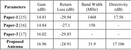
The following table 4 shows the comparison of various antenna parameters like return loss, gain, bandwidth and directivity of the existing methods with the proposed method.
TABLE 4: Comparison of Proposed array results with Reference papers
Parameters Gain
(dB)
Return Loss (dB)
Band Width (MHz)
Directivity (dB)
Paper-1 [15] 14.81 -29.94 1468 17.56
Paper-2 [16] 14.84 -27.1 150 -
Paper-3 [17] 16.02 -29.85 - -
Proposed
Antenna 16.96 -24.91 31.9 17.106
From the above table the gain of the proposed QWT Fed 4x4 Circular Patch Phased Array antenna is 16.96dB, which is highest compare to other papers. As gain increases the distance between
transmitter receiver increases, which can be used for long distance communications.
8. ADVANTAGES
The main advantage of the proposed work includes High Gain, High directivity, Narrow beamwidth, Highest efficiency, Light weight and low volume, Low profile planar configuration which can be easily made conformal to host surface, Low fabrication cost, hence can be manufactured in large quantities and Supports both, linear as well as circular polarization.
9. APPLICATIONS
The proposed QWT Fed 4x4 Circular Patch Phased Array antenna can be used in Airborne
Applications such as Wireless Mobile
communication, Satellite navigation Systems, radar and telemetry, tracking, and command (TTC) for mini satellites.
10. CONCLUSION
4x4 Circular Patch Phased Array was designed and successfully simulated. The gain of proposed array is 16.963 dB, VSWR is 1.1872, return loss is -24.9163 dB, Bandwidth is 31.9 MHz, elevation HPBW is 21.43570, Azimuth HPBW is 12.77560 and the elevation beam is steered in various directions for various phase angles. The radiation characteristics obtained for the proposed array is very much useful for L band airborne applications such as satellite navigation, mobile wireless communication, radar and telemetry, tracking, and command (TTC) for mini satellites.
ACKNOWLEDGEMENTS
Extending our grateful thanks to the authorities of Acharya Nagarjuna University (ANU) for their support and encouragement to write this paper.
REFERENCES
[1] Shen, L. C., et al., "Resonant Frequency of a Circular Disk Printed-Circuit Antenna," IEE Trans. On antennas and Propagation, Vol.AP-25, 1977, pp. 595-596.
[2] Watkins, j., "Circular Resonant structures in Microstrip," Electron. Lett. Vol. 5, 1969, pp. 524-525.
[3] Manoj Singh, Ananjan basu and S.K.Koul, “ Circular Patch Antenna with Quarter wave
Transformer Feed for Wireless
Communications”,” IEEE
[image:7.612.89.302.587.668.2]ISSN: 1992-8645 www.jatit.org E-ISSN: 1817-3195 [4] “Phaed Array Simulation Using Circular Patch
Radiators”, Klaus Solbach, IEEE Transitions. Antennas and propagation Vol.AP43, No.8; p.p.1053-1058, Aug 1986.
[5] “A 7.5GHz micro strip phased array for aircraft-to-satellite communication” F.W. Cipole, IEEE Transactions. Vol.AP29, No.1, P.P.166-170, Jan 1981.
[6] “S Band Phased Patch Array Design for Satellite Apllications”, Grer Zomchek, Sharad Laxpati, IEEE, 7803-8883, 2005.
[7] K. Shambavi, Z C Alex, T. N. P. Krishna, “Design and Analysis of High Gain Millimeter wave Microstrip Antenna Array for Wireless Applications”, Journal of Theoretical and Applied Information Technology.
[8] P.S.V.Kumar, P. Jagadamba, M. N. Giri
Prasad, “” Performance analysis of 4x4 Circular Patch Phased Array Antenna Using HFSS”, International Journal of Innovative
Research in Electrical, Electronics,
Instrumentation and control Engineering”, ISSN: 2321 – 2004 (O), 2321-5526(P), Volume-4, Issue 3. March 2016.
[9] Ramesh Kumar, Gian Chand, Monish Gupta, Dinesh Kumar Gupta, “Circular Patch Antenna with Enhanced Bandwidth using Narrow Rectangular Slit for Wi-Max Application,” IJECT Vol. 1, Issue 1, December 2010. [10]Balanis, C.A., Antenna Theory Analysis and
Design, John Wiley & Sons, New York, 1997. [11]I.J. Bhal and P. Bhartia, Microstrip antenna,
Artech House, Dedgham, MA, 1980.
[12]Pozar, D.M. Microwave Engineering, John Wiley & Sons, New York, 1998.
[13]"Antenna Engineering," in R.C. Johnson and H. Jasic (Eds.), Microstrip Antenna (2nd ed.), McGraw Hill, New York, 1984.
[14]I.J. Bhal and P. Bhartia, Microstrip antenna, Artech House, Dedgham, MA, 1980.
[15]James, J.R., P.S. Hall, and C. Wood, Microstrip antenna: Theory and design, Peter Peregrinus, London, UK, 1981.
[16]“Design & Development of a 32 Elements X-band phased array antenna for Airborne & Space Borne SAR Payloads”, A.K.M. Shafaat Ali, Majsa, Raza, Mussadiq Ali Shah, IEEE, Conference, Precedings, Jan 2012.
[17]Tommy Reynalda. A munir, E Bharata “ Characterization of 4x4 High Gain Microstrip array antenna for 3.3ghz wimax application”,
The 6th International Conference on
telecommunication systems, services and
applications 2011,