Full Length Research Article
ANALYSIS OF FLOW THROUGH RECTANGULAR MINI CHANNEL WITH SURFACE IRREGULARITIES
*Anooplal, B., Binoy Baby and Joseph, C. J.
Department of Mechanical Engineering SJCET Palai
ARTICLE INFO ABSTRACT
This paper presents numerical investigations on forced convection in mini-channels with realistic cross-sectional shapes. The numerical study is based on Finite Difference solution of the governing equations, incorporating actual irregular cross-sectional profile of fabricated channel in the flow domain, using image processing. Numerical studies have been performed using ANSYS Fluent 13.0 to obtain the temperature distributions and calculate heat transfer parameters in water flow through mini-channel. The Nusselt number values were compared and contrasted with apparent regular geometry as well as the actual irregular geometry. The findings suggest that some of the observed deviations in the performance of small channels, compared to theoretical results, are possibly due to the assumption of regular domain shapes while performing theoretical analysis.
Copyright © 2015 Anooplal et al. This is an open access article distributed under the Creative Commons Attribution License, which permits unrestricted use, distribution, and reproduction in any medium, provided the original work is properly cited.
INTRODUCTION
Investigations on the flow and heat transfer behaviour of mini channels, both experimental and theoretical, have been compiled in many publications. While performing theoretical analysis, or using theoretical results to make comparisons with experimental results, often it is assumed that the channels possess regular geometrical shapes, with perfectly defined surfaces. In reality, the actual cross-sectional geometries produced by the fabrication techniques could be much different from these assumed perfect geometries, so that the assumption does not predict the performance correctly in an analysis. Single-phase convective heat transfer in a compact heat sink of hydraulic diameter 300 µm and depth 800 µm with relative roughness in the range 4–6% was investigated experimentally, by Shen et al. (2006). The friction factors and the local and average Nusselt number values were deviated significantly from theoretical predictions, depending on the surface roughness and the cross-sectional aspect ratio. Experimental investigation by Jiang et al. (1997) on the laminar flow of liquid in silicon micro channels with different cross-sections has shown that, for non-circular ducts, the values of Cf & Re are smaller than predicted values. Wu and Cheng (2003) performed experimental studies on laminar heat transfer and pressure drop in water flowing
*Corresponding author: Anooplal, B.,
Department of Mechanical Engineering SJCET Palai
through trapezoidal silicon micro-channels and reported that the values of Nusselt number and the apparent coefficient of friction depended greatly on different geometric parameters. The effect of the channel wall roughness on adiabatic flow in circular micro-channels has been studied by Celata et al. (2006). An increase in the friction factor was observed for the smallest diameter of 126 µm studied, with respect to classical results. It was concluded that this increase was caused by the actual deformation of the channel circularity, rather than the increased friction at the roughened wall.
Silva et al. (2008) investigated the influence of surface phenomena on micro scale flows using Micro Particle Image Velocimetry (MPIV). Investigations on a micro- channel of hydraulic diameter 637 µm with rough walls having relative roughness 1.6% and a very irregular cross- sectional shape showed that the Poiseuille numbers differed by 11% with respect to that in a channel with smooth walls. This emphasized the need to account for wall roughness in the analysis of flow in channels of small dimensions. An approximate model has been developed by Bahrami et al. (2007) to investigate the pressure drop in smooth mini channels and micro channels of arbitrary cross-sections, with incompressible, laminar and fully developed flow. The results were found to be functions of only the geometrical parameters of cross-section. Based on reported work in the literature, Suresh et al. (2003) have pointed out that in micro channels;
ISSN: 2230-9926
International Journal of Development Research
Vol. 5, Issue, 04, pp. 4265-4270, April,2015
International Journal of
DEVELOPMENT RESEARCH
Article History:
Received 09th January, 2015
Received in revised form 27th February, 2015
Accepted 21st March, 2015
Published online 30th April, 2015
Key words:
the flow behaviour is strongly affected by the hydraulic diameter and aspect ratio of the channel. It was summarized that, research on single-phase flow in micro channels has to be focused on three aspects: (i) effect of channel dimension and geometry (ii) critical Reynolds number and (iii) correlations in terms of fluid properties and micro-channel geometry. Due to the surface irregularities, fluid flow and heat transfer parameters such as the friction factor and Nusselt number can be expected to deviate from values predicted by conventional correlations considering regular cross-sections. Judy et al. (2005) pointed out surface irregularities affect the cross-sectional shape, and the flow area, thus affecting both the frictional and inertial effects. Etching process and the micro machining process produce surface with irregularities which alter the apparent cross sectional geometry of channels, the effects of which are predominant in small dimension channels. The flow and heat transfer parameters in this can be expected to deviate from values predicted by conventional correlations since the surface irregularities affect the geometrical parameters such as perimeter and flow area, cross sectional shape, the surface roughness.
[image:2.595.310.560.192.312.2]Hakamada et al. (2008) was fabricated micro-channel with a three dimensional configuration by spacer method, in which spiral aluminium was compacted with copper powder at 300MPa and sintered at 1173K. After sintering aluminium wire was removed by alkali leaching. They proposed that the spacer method is an effective fabricating method for three dimensional configuration micro channels, compared to conventional methods. Pan et al. (2009) proposed a novel multi cutter milling process for multiple parallel micro channels. This method could be used for cost effective commercial applications and mass production of micro channel arrays. Experimental investigations under different machining conditions have been conducted for the feasibility of the new fabrication method. Binoy and Sobhan (2012) investigate a two-dimensional, fully developed, convective heat transfer in compact passages, incorporating the effects of the surface irregularities by finite-difference method. The results are validated experimentally using Michelson interferometry.
Fig. 1. Fabricated micro channels by Multi Cutter Milling Process (Pan et al., 2009)
MATERIALS AND METHODS
The configuration of the rectangular mini- channels fabricated on an aluminium substrate is shown schematically in Fig. 2.
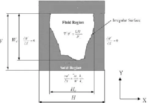
[image:2.595.309.552.445.615.2]In this arrangement, the channels have a uniform cross-section of width W, height H, and a length L. In the computation domain, it is assumed that the substrate dissipates heat uniformly into the fluid. Water is used as the cooling fluid, which flows at a constant rate through the channels. Schematic of the typical cross- section of the mini-channel, used as water as the cooling fluid, which flows at a constant rate through the channels. Schematic of the typical cross-section of the mini-channel, used as the computational domain is shown in Fig. 3, along with the non-dimensional governing equations and boundary conditions.
Fig. 2. Physical model of a mini-channel arrangement (Binoy Baby and Sobhan, 2014)
[image:2.595.56.272.537.691.2]Corresponding to the fabricated channels used in the present work, the bottom and side walls are aluminium as the channels are fabricated on an aluminium block, and have irregular surface profiles. The channel is fabricated using the micro-machining process. The actual surface profiles for the aluminium walls, obtained using microscopy and boundary tracing technique, has been incorporated in the analysis.
Fig. 3. Domain of Computational Analysis, with non- dimensional governing equations and boundary conditions (Binoy Baby and
Sobhan, 2014)
The general assumptions based on which the mathematical model is formulated are the following:
Velocity is considered to be zero at all boundaries except at channel inlet and outlet.
1. There are no radiation effects. 2. The flow is unidirectional. 3. Buoyancy effect is neglected.
4. Cavitation effects are ignored. 5. The flow is incompressible 6. Steady state analysis.
The buoyancy effect is neglected as heat transfer characteristics are being invest majority of the length of the mini-chan developed condition. Temperature field is d Fluid used for the analysis is wate incompressible. Following are the governing
(i) The momentum equation
(ii)The energy equation:
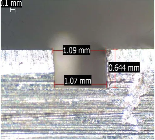
The no-slip boundary condition is used at of the substrate. The boundary conditions analysis include the symmetric boundar temperature, uniform constant heat flux boundary. The analysis is divided into two p deals with the construction of a regular channel and its analysis. Second phase a rea section) mini channel is constructed an analysis a real mini channel is to be obtai coordinates of points is to be taken from a m help of MATLAB. The photograph is show steps used to obtain the coordinates of th follows (i) Read the image (ii) Noise rem thresholding (iii) conversion to bina Determination of coordinates of a pixel Trace the boundary from the specified p image and plot the boundary. The boun shown in the Fig. 5.
Fig. 4. Micrograph of the cross-section of
forced convection tigated since the nnel is in the fully defined as steady. ater, hence it is
g equations
at the solid walls s for heat transfer ry conditions in x on the bottom phases; first phase rectangular mini al (irregular cross- nd analysed. The tained for that the micrograph with the wn in Fig. 4. The he channel are as moval and image ary image (iv) on boundary (v) pixel. Display the undary obtained is
[image:3.595.311.550.57.260.2]f mini channel
Fig. 5. Surface profile o
RESULTS AND DISCUSSION
[image:3.595.307.557.501.734.2]The first step in the analysis through a regular mini chan drawn in ANSYS 13 workbenc called as fluid domain becaus fluid flow actually taking plac called as solid domain because for our consideration. Constru with similar geometries of always a considerable differen rectangular channels that can c technologies around us and the have considered in the first consider the actual difficulties rectangular duct in a metal, as profile as shown in Fig. 6, as a
Fig. 6. Geometry of real mini
of the boundary obtained
S AND DISCUSSION
s is the evaluation of the flow nnel. The required geometry is ch. The inner rectangular duct is use it is the region in which the lace. The outer rectangular duct is e it is made of aluminium metal uct rectangular mini channel the real channel. There are nce between the actual possible cut, in a metal with the available e ideal rectangular channel that stage. By giving the space to ties that can face in order to cut a assume geometry with a random
actual case of duct.
[image:3.595.40.287.515.739.2]Boundary Conditions
Following are the boundary conditions defined for the simulation:
Inlet temperature = 28.8 ℃
Mass flow rate at inlet = 0.00027638 kg/s Inlet pressure = 1 atm.
Wall = No slip wall
Fluid = Incompressible fluid (water)
When a real fluid flow past a solid body or a solid wall, the fluid particle adhere to the boundary and condition of no slip occurs. This means that the velocity of fluid close to the boundary will be same as that of the boundary. The following results are obtained from the analysis after completing the analysis in the FLUENT. These results are obtained with the help of CFD-POST. The results for each phase of analysis are shown below
Rectangular Mini Channel
[image:4.595.64.528.79.240.2]The rectangular section with dimensions L=100mm, 1.09 x 0.644mm was analysed and the following results were obtained. The Fig. 7 shows the velocity profile of the flow.
Fig. 6. Geometry of real mini channel drawn in Workbench
[image:4.595.311.555.412.622.2]It is observed that the velocity is maximum at the inside and minimum at the layer near the channel surface. It is due to the friction formed between the wall and the fluid layer. The maximum velocity observed is 0.741m/s for a mass flow rate of 0.00027638 kg/s. There is no variation in velocity along the length in the channel. Fig.8. shows the distribution of temperature of liquid alone at the outlet. It can be seen that minimum temperature at the centre and maximum temperature near the surface. The Fig. 9. shows the variation of Nusselt number along the length, in the fully developed region the Nusselt number was found to be 3.58. This value is in par with the theoretical Nusselt number value for rectangular section.
Fig. 8. Temperature distribution of liquid alone at the outlet
Real (irregular cross-section) Mini channel
The rectangular section with dimensions L=100mm, irregular was analysed and the following results were obtained. The Fig. 10. shows the velocity profile of the flow. It is observed that the velocity is maximum at the inside and minimum at the layer near the channel surface. It is due to the friction formed between the wall and the fluid layer. The maximum velocity observed is 0.725m/s for a mass flow rate of 0.00027638 kg/s. Velocity is same along the length.
Table 1. Details of mini channel analysed
Regular mini channel
Geometric dimensions L=100mm, 1.09x0.644mm
Flow rate 0.00027638 kg/s
Inlet Fluid Temperature 301.8 K Thermo Physical Property Aluminium
Thermal Conductivity Aluminium=237W/mK, Water=0.628 W/m-K
Density Water=995 kg/m3
Irregular mini channel
Geometric dimensions L=100mm, irregular
Flow rate 0.00027638 kg/s
Inlet Fluid Temperature 301.8 K Thermo Physical Property Aluminium
Thermal Conductivity Aluminium=237 W/m K, Water=0.628 W/m-K
Density Water=995 kg/m3
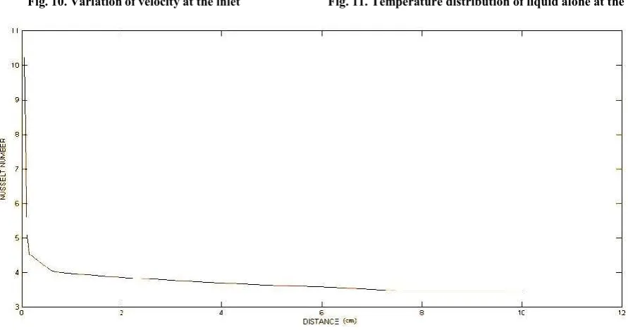
[image:4.595.38.291.554.740.2]Fig. 9. Variation of Nusselt number along the length of the channel
Fig. 10. Variation of velocity at the inlet Fig. 11. Temperature distribution of liquid alone at the outlet
[image:5.595.53.546.319.506.2] [image:5.595.77.523.520.754.2]Temperature distribution of liquid alone at the outlet is shown in Fig.11, the cold water carries away heat from the surface of the channel. The temperature is maximum near the surface and minimum centre of the flow. The Fig. 12. shows the variation of Nusselt number along the length, in the fully developed region the Nusselt number was found to be 3.47. This value is deviated from the theoretical Nusselt number value for rectangular section.
Validation of the results obtained
For validating the results obtained Nusselt number values are compared with the theoretical value of Nusselt number. It was found that the Nusselt number of real cross-section (irregular geometry) is deviated from the theoretical value. This deviation of Nusselt number is due to the change in geometry of the real (irregular) cross- section channel.
Conclusion
A numerical model has been utilized to analyse fully developed laminar flow in mini channel incorporating the actual cross-sectional geometry with the surface irregularities in the boundaries. Boundary profile captured using MATLAB. Flow and heat transfer characteristics of irregular-cross-section channels are compared with those with smooth regular cross-section geometry, and the deviations are studied. The Nusselt number for the channel with irregular cross section is observed to be 3.1% lesser than those for channels with regular smooth surface geometry and 3.9% lesser than the theoretical value. The computational results for a channel with surface irregularities have been benchmarked with theoretical result. The investigation suggests that accurate prediction of flow and heat transfer characteristics of channels of small cross-section requires consideration of surface irregularities in defining the domain of analysis while performing numerical computations with a view to compare with theoretical results. Comparisons of experimental results with theoretical or computational results based on an assumption of regular surface geometries would often be mistaken as actual deviations, which could be wrongly interpreted as due to fundamental differences in the flow behaviour in small-cross-section channels.
REFERENCES
Shen, S. J. L.; Zhou, Xu. J. J. and Chen, Y., 2 0 0 6 . Flow And Heat Transfer In Micro-Channels With Rough Wall Surface, Energy Conversion and Management, Vol. 47, Issues 11–12, pp. 1311–1325.
Jiang, X. N.; Zhou, Z. Y.; Huang, X. Y. and Liu, C. Y., 1997. Laminar Flow Through Micro-channels Used For Micro- scale Cooling Systems, IEEE/ CMPT, Electronic Packaging Technology Conference, 1st ed., Proceedings of the 1997, pp. 119 – 122
Wu, H. Y. and Ping Cheng., 2003. An Experimental Study Of Convective Heat Transfer In Silicon Micro-channels With Different Surface Conditions, International Journal of Heat and Mass Transfer, Vol. 46, Issue 14, pp. 2547–2556. Celataa, G. P.; Cumob, M.; McPhaila, S. and Zummo, G.
2006. Characterization Of Fluid Dynamic Behaviour And hannel Wall Effects In Micro-tube, International Journal
of Heatand Fluid Flow, Vol. 27, Issue 1, pp. 135–143.
Gonçalo Silva, Nuno Leal and Viriato Semiao, 2008. PIV and CFD Characterization Of Flows In A Micro-channel Velocity Profiles, Surface Roughness And Poiseuille Numbers, International Journal of Heat and
Fluid Flow, Vol. 29, Issue 4, pp. 1211–1220.
Bahrami, M., M.M. Yovanovich and J.R. Culham, 2007. A novel solution for pressure drop in singly connected microchannels of arbitrary cross-section, Int. J. Heat MassTransfer 50, 2492–2502.
Suresh, V.; Garimella. and Sobhan, C. B. 2003. Pressure Drop of Fully-Developed, Laminar Flow in Micro-channels of Arbitrary Cross-Section, Journal of Fluids Engineering/ Transport In Micro-channels A Critical Annual review of heat transfer, Vol. 128, Issue. 5, pp. 1-50.
Judy, J.; Maynes, D. and Webb, B. W. 2005. Characterization Of Frictional Pressure Drop For Liquid Flows Through Micro-Channels, International Journal Of Heat And Mass Transfer, Vol. 45, pp. 3477-3489 (9).
Hakamada, M.; Asao, Y.; Kuromura, T.; Chen, Y.; Kusuda, H. and Mabuchi, M. 2008. Processing Of Three Dimensional Metallic Micro Channels By Spacer Method, Material Letters, Vol. 62, pp. 1118-1121.
Pan, M.; Zeng, D. and Tang, Y. 2009. Feasibility Investigations On Multi Cutter Milling Process: A Novel Fabrication Method For Micro Reactor With Multiple Micro-channels, Journal Of Power Source, Vol. 192, pp. 562-572.
Binoy Baby and Sobhan, C. B. 2012. Investigations On Forced Convection In Compact Passages With Surface Irregularities, Heat Transfer Engineering, Vol.33(13), pp.1105–1119
Binoy Baby and Sobhan, C. B. 2014. Numerical And Experimental Investigations On Forced Convection In Meso-Channels With Irregular Geometry Of Cross- Section, International Journal of Heat and Mass Transfer, Vol. 70, pp. 276-288.