ISSN: 2278 – 7798 All Rights Reserved © 2014 IJSETR
2400
A SURVIELLANCE ROBOT WITH AUTOMATIC CHARGING UNIT FOR HOME SECURITY
N. Sravanthi
Dept.of Electronics and Communication Engineering Vardhaman college of Engineering
Hyderabad, India
J.Krishna Chaithanya
Dept.of Electronics and Communication Engineering Vardhaman college of Engineering
Hyderabad, India
Abstract- Now days, it is easy to keep guards outside the
house for home security. But always we cannot rely on guards. In some cases, people will lock the house for long days The proposed system is composed of a surveillance robot and a docking station. The palm-sized surveillance robot has a triangular shape with three wheels. It communicates with the general wireless home router through Wi-Fi. It communicates with the docking station through ZigBee and serves as a mobile wireless sensor network gateway. The docking station has a trapezoidal structure with an arc-shaped docking interface. A docking method based on the self-localization of the robot and the infrared detectors of the docking station is proposed. The robot can return to the docking station for recharging operations when the on-board battery is too low. The experimental results show that the prototype robot achieved a success rate of 90% after 60 different docking attempts1.
Keywords-ARM, Zigbee, Sensors module,CMOS Cam, Relay Unit
I. INTRODUCTION
Home security is one of the typical applications of home robots. In traditional home security systems, monitoring devices are usually mounted on fixed locations such as doors, windows and walls. A home surveillance system based on an embedded system with multiple ultrasonic sensor modules has been presented in If any intruder passes through the ultrasonic sensing area, the ultrasonic transmission will be blocked by the human body.
The technique is followed in the project to reduce the energy consumption of robot. In this project the robotic unit can be charged using wireless power transmission method. The development of a patrol robot system for home security with some interaction functionalities has been presented in The system integrates a variety of sensors to gather environmental information and detect abnormal events such as fire alarm, intruder alert and gas leakage.
Fig. 1 Architecture.
II. SYSTEM DESIGN
The surveillance robot can work in three modes according to user requests and task properties:
i. patrolling mode ii. first responder mode iii. remote control mode.
In the patrolling mode, the surveillance robot wanders around in the rooms or follows predefined routes autonomously. When security related information is acquired, it will be sent to the home server for further analysis. In the first responder mode, the surveillance robot is programmed to work in cooperation with other fixed monitoring devices.
When one of those devices reports a security event to the surveillance robot, it will navigate to the target region to perform on-site inspections. It overcomes obstacles on its routes by making a detour. In the remote control mode, the surveillance robot will be guided to the region of interest under control of a remote user. Users can access the home security system through various terminals such as PCs, PDAs and mobile phones.
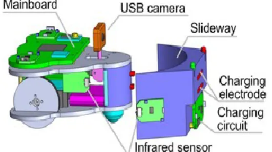
Fig. 2. CAD model of the proposed surveillance robot and the docking station.
The docking interface of the robot is a semi cylinder with two charging electrodes on the front. The charging electrodes are installed on elastic supports so that the impact of the docking station in the docking process can be effectively buffered. The docking interface of the docking station has an arc shape that can guide the robot to finish electrical connections with the docking station. The proposed architecture of the docking interface can tolerate a robot position error up to 7cm and an angle error up to 60 degrees when the robot is performing the docking action.
ISSN: 2278 – 7798 All Rights Reserved © 2014 IJSETR
2401
III.
BLOCK DIAGRAM
Fig. 3. Hardware components of the surveillance robot.
Fig. 4. Hardware components of the docking station.
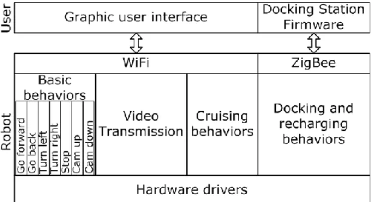
Fig. 5. Software architecture of the surveillance robot.
The software architecture of the surveillance robot is shown in Fig. 5. The embedded program in the robot can implement basic locomotion behaviors and other high-level behaviors such as video transmission, cruising, docking and recharging. The robot communicates with the docking station through ZigBee and serves as a mobile wireless sensor network gateway. More docking stations can be added to the system by serving as additional wireless end nodes. Therefore it will be more flexible for docking and recharging the robot. The graphic user interface at the host computer communicates with the robot through WiFi. In the WiFi network, the robot changes its role to an end device.
IV.
DOCKING STATION
Fig. 6. Outline of the docking area.
Each side of the docking station has an IRsensor to detect obstacles ahead. According to the outputs ofthe IR sensors, the relative position between the robot and the docking station can be determined. Thereforethe robot will connect to the docking station automatically. During the docking process, the IR sensors on the robot will temporarily stop working to avoid interfering with the IR sensors on the docking.
ISSN: 2278 – 7798 All Rights Reserved © 2014 IJSETR
2402
1. Locomotion Control:
Fig 7. Locomotion model of the surveillance robot.
The proposed surveillance robot is designed with a rear-wheel differential drive structure. Its locomotion model. We select a center point O that is located in the center of the rear axle for locomotion modeling. Using the trajectory of the center point as the robot trajectory, we get the locomotion.
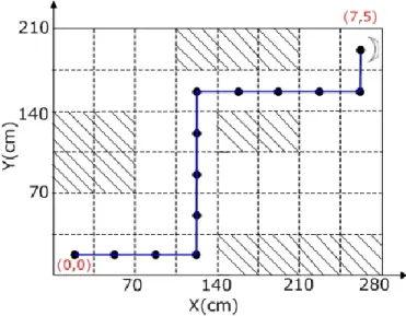
Fig 7. Grid map of the robot workspace. The shadowed grid cells represent the areas occupied by obstacles. The
blue line indicates an example path from the grid coordinates (0, 0) to (7, 5).
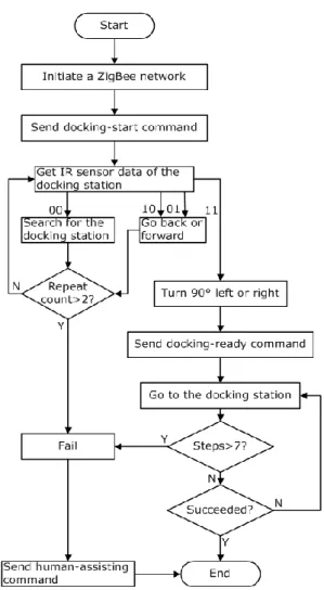
1. DOCKING METHOD
If the surveillance robot wants to recharge by itselfwhenever the battery voltage is low, it must be able tonavigate back to the docking area and connect with thedocking station automatically. Some key techniques include self-localization, global and local path planning, docking and charging status detection, and fault-tolerant processing. Before reaching the docking area, the robot mainly depends on its own locomotion capabilities to work. In the final docking process, the robot
and the docking station work cooperatively to complete the task.
Fig 8: The Final Docking Process When The Robot Is Detected By One Of The IR Sensors On The Docking
Station
V.
HARDWARE DESIGN
The hardware for the rangefinder can be broken down into three functional units, the receiving circuit, the transmitting circuit, and the MCU circuit. The receiver and transmitter circuits can work independently of the MCU, which made testing with a signal generator quite useful. This allowed one of us to work on the hardware while the other worked on the software independently and not require one to be dependent on the other for testing.
1.ARM Processor:
The ARM7 family includes the ARM7TDMI, ARM7TDMI-S, ARM720T, and ARM7EJ-S processors. The ARM7TDMI core is the industry’s most widely used 32-bit embedded RISC microprocessor solution. Optimized for cost and power-sensitive applications, the ARM7TDMI solution provides the low power consumption, small size, and high performance needed in portable, embedded applications. The ARM7TDMI core uses a three-stage pipeline to increase the flow of instructions to the processor. This allows multiple simultaneous operations to take place and continuous operation of the processing and memory systems. As the processor is having a high speed it is easy to make the communication between the RF module and the Image acquisition module.
2.Wireless Communication
The XBee and XBee-PRO OEM RF Modules were engineered to meet IEEE 802.15.4 standards and support the unique needs of low-cost, low-power wireless sensor networks. The modules require minimal power and provide reliable delivery of data between devices. The modules operate within the ISM 2.4 GHz frequency band and are pin-for-pin compatible with each other The XBee®/XBee-PRO OEM RF Modules interface to a host device through a logic-level asynchronous
ISSN: 2278 – 7798 All Rights Reserved © 2014 IJSETR
2403 serial port. Through its serial port, the module can
communicate with any logic and voltage compatible UART; or through a level translator to any serial device (For example: Through a Digit proprietary RS-232 or USB interface board)
VI.
DESIGN FLOW
Fig. 9. Flowchart of the docking station control in the docking process.
Fig.10. Flowchart of the surveillance robot control in the docking process.
VII. EXPERIMENTAL RESULTS
Fig. 11. Trajectories of the the surveillance robot during the process of navigating back to the docking area.
ISSN: 2278 – 7798 All Rights Reserved © 2014 IJSETR
2404
Fig. 12.Video frames cut from the video captured during the process of navigating back to the docking area for
recharging
VIII.
CONCLUSION
In order to cover the entire room , the robot module can able to turn in various angle with manual and automatic control. Under the absence of human the processor will keep the camera in the sleep mode. The technique is followed in the project to reduce the energy consumption of robot. In this project the robotic unit can be charged using wireless power transmission method. Ultrasonic signal confirms the robot that it is in power transmission region. This project uses the Matlab platform for the image visualization.
IX.
REFERENCES
[1] E. Sato, T. Yamaguchi, and F. Harashima, [1] G. Song, Z. Wei, W. Zhang and A. Song, “A hybrid sensor network system for home monitoring applications”, IEEE Trans Consum Electron, Vol. 53, No. 4, pp. 1434-1439, 2007. [2] G. Song, Y. Zhou, Z. Wei and A. Song, “A smart node architecture for adding mobility to wireless sensor networks,” Sens Actuators A Phys, vol. 147, no. 1, pp. 216–221, 2008. [3] G. Song, K. Yin, Y. Zhou and X. Cheng, “A Surveillance Robot with Hopping Capabilities for Home Security,” IEEE Trans Consum Electron, Vol. 55, No. 4, pp. 2034-2039, 2009. [4] C. D. Nugent, D. D. Finlay, P. Fiorini, Y. Tsumaki and E. Prassler, “Home automation as a means of independent living,” IEEE Trans. Autom. Sci. Eng., Vol. 5, No. 1, pp. 1-8, Jan 2008.
[5] Yoo Oh, Jae Yoon, Ji Park, Mina Kim and Hong Kim, “A name recognition based call-and-come service for home
robots”, IEEE Trans Consum Electron, Vol. 54, No. 2, pp. 247-253, 2008.
[6] Y. W. Bai, L. S. Shen and Z. H. Li, “Design and implementation of an embedded home surveillance system by use of multiple ultrasonic sensors”, IEEE Trans Consum Electron, Vol. 56, No. 1, pp. 119-124, 2010.
[7] W. Lao, J. Han and Peter H.N. de With, “Automatic video-based human motion analyzer for consumer surveillance system”, IEEE Trans Consum Electron, Vol. 55, No. 2, pp. 591-598, 2009.
[8] Y. Zhao and Z. Ye, “A low cost GSM_GPRS based wireless home security system”, IEEE Trans Consum Electron, Vol. 54, No. 2, pp. 567-572, 2008.
[9] I.K. Hwang and J.W. Baek, “Wireless access monitoring and control system based on digital door lock”, IEEE Trans Consum Electron, Vol. 53, No. 4, pp. 1724-1730, 2007. [10] C. Chang, K. Chen, H. Lin, C. Wang and J. Jean, “Development of a patrol robot for home security with network assisted interactions”, in SICE Annual
Conference 2007, Kagawa University, Japan, 2007, pp. 924-928.
[11] Y. Kim, H. Kim, S. Lee and K. Lee, “Ubiquitous home security robot based on sensor network”, in IEEE/WIC/ACM Int. Conf. on Intelligent Agent Technology, Hong Kong, China, 2006, pp. 700-704.
[12] R.C. Luo, P.K. Wang, Y.F. Tseng and T.Y. Lin, “Navigation and mobile security system of home security robot”, in IEEE Int. Conf. on Systems, Man
and Cybernetics, Taipei, Taiwan, 2006, pp. 169-174.
[13] R.C., Luo, T.Y. Hsu, T.Y. Lin and K.L. Su, “The development of intelligent home security robot”, in IEEE Int. Conf. on Mechatronics, Taipei, Taiwan, 2005, pp. 422-427. [14] Se-gon Roh, J. H. Park, Y. H. Lee, Y. K. Song, K. W. Yang, M. Choi, H.-S. Kim, H. Lee, and H. R. Choi, “Flexible docking mechanism with error-compensation capability for auto recharging system of mobile robot,” Int. Journal of Control, Automation, and Systems, vol. 6, no. 5, pp. 731-739, 2008.
[15] W. Grey Walter, “The Living Brain”, W.W. Norton, New York, 1963.