Log Angles: Characteristic Angles of Crystal Orientation Given
by the Logarithm of Rotation Matrix
*1Kunio Hayashi
1,*2, Motoki Osada
2,*3, Yuki Kurosu
1,*2, Yoji Miyajima
1and Susumu Onaka
1,*4 1Department of Materials Science and Engineering, Interdisciplinary Graduate School of Science and Engineering, Tokyo Institute of Technology, Yokohama 226–8502, Japan2Department of Metallurgical Engineering, School of Engineering, Tokyo Institute of Technology, Tokyo 152–8552, Japan
A rotation matrix R with respect to a reference frame is used to describe certain crystal orientation. The logarithm of R, ln R is a skew symmetric tensor with three independent elements of real numbers. The goniometer-stage model in the present study shows that the three inde-pendent elements of ln R are the characteristic angles of R representing the rotation angles around coordinate axes. Different from various kinds of the Euler angles, the characteristic angles called the log angles are uniquely determined for certain R. [doi:10.2320/matertrans.M2015454]
(Received December 9, 2015; Accepted January 15, 2016; Published March 25, 2016) Keywords: logarithm of matrix, misorientation, microstructure, Euler angles, axis/angle pair
1. Introduction
Crystal orientations and their changes are important factors to investigate material microstructures.1–3) For instance, to
in-vestigate changes of microstructures by rolling and plas-tic-deformation mechanisms during rolling, crystal orienta-tions of plate-like single crystals before and after rolling are compared.4–6) Depending on the initial orientations or rolling
conditions, significant changes of crystal orientations may occur. However, the single crystalline states are sometimes maintained even after the changes of crystal orientations. In such cases, the orientation changes are often discussed by us-ing the reference frame of rollus-ing (RD: rollus-ing direction, TD; transverse direction, ND: normal direction).4–6)
When indicating a crystal orientation with respect to a ref-erence frame, we can make geometrically sound discussion by using a three-dimensional orthogonal rotation matrix R. Although the number of independent elements of the 3x3 ma-trix R is three, R generally has nine different elements. Be-cause of the complexity of the relationships among the ele-ments of R, intuitive understanding of the changes of crystal orientations from changes of the elements of R is not easy.
To grasp the meaning of crystal orientation described by R, the Euler angles of R consisting of a set of three angles are often used. The rotation matrix R can be decomposed into the product of three successive rotations around the x, y or z coor-dinate axes of the frame. The Euler angles are the three rota-tion angles around the coordinate axes.7) However, the values
of the three rotation angles for certain R change depending on the order of the three successive rotations. This shows that various sets could exist for the Euler angles and the three an-gles cannot be determined uniquely for certain R.7) For
exam-ple, when we would like to consider a change of crystal ori-entation of single crystal caused by rolling and evaluate a ratio of the rotation around TD in the whole rotation4,6,8), the
ratio cannot be uniquely determined from the concept of the Euler angles.
Similar to the exponential and logarithmic functions of number, the exponential and logarithmic functions of matrix can be defined by the sum of series.9–11) It is known that the
logarithm ln R of R is a skew symmetric tensor with three independent elements of real numbers.9–11) In this study, we
will show that the three elements of ln R are the set of three characteristic angles of R. The characteristic angles called the log angles give the intuitive understanding of the crystal ori-entation described by R. Different from the various Euler an-gles, the log angles are uniquely determined for certain R. As an example to compare the log angles with the Euler angles, we will discuss previous experimental results12,13) on the
change of crystal orientation. As an application of the log an-gles, we will analyze our recent results on the changes of crystal orientations observed in a single crystal after rolling.
2. Analysis
2.1 Combination of the rotations around the coordinate axes
When Rx, Ry and Rz are respectively the rotation matrices
around the x, y and z coordinate axes of the orthogonal frame, the elements of these matrices are written as
Rx(θ)=
1 0 0
0 cosθ −sinθ 0 sinθ cosθ
, (1-a)
Ry(ϕ)=
cosϕ 0 sinϕ
0 1 0
−sinϕ 0 cosϕ
, (1-b) and
Rz(ψ)=
cosψ −sinψ 0 sinψ cosψ 0
0 0 1
, (1-c)
where θ, φ and ψ are respectively the rotation angles around the x, y and z coordinate axes.
We can represent any R with the product of such three
ba-*1
This Paper was Originally Published in Japanese in J. Japan Inst. Met. Mater. 79 (2015) 9–15.
*2
Graduate Student, Tokyo Institute of Technology *3
Undergraduate Student, Tokyo Institute of Technology *4
sic rotation matrices. Here we consider R consisting of the product of Rx with θ1, Ry with φ1 and Rz with ψ1 in this order:
[image:2.595.111.221.71.269.2]R=Rx(θ1)Ry(ϕ1)Rz(ψ1). (2)
Figure 1 is a goniometer-stage model,14) which is
conve-nient to understand the combination of rotations. In this mod-el, a goniometer stage consists of three parts connected in series and has the function of triaxial rotations. The goniom-eter stage and the reference frame with the x, y and z coordi-nate axes are fixed on a base plate. A crystal with the x, y and
z coordinate axes is located on the top of the goniometer stage. When all of θ1, φ1 and ψ1 are zero, the primed axes are
parallel to the unprimed reference axes. The rotation angles of the three parts determine the directions of the primed axes of the crystal. The directions of the primed axes using the reference x-y-z frame are given by R as
x-axis//R
1 0 0
,y-axis//R
0 1 0
, z-axis//R
0 0 1
. (3)
The goniometer-stage model in Fig. 1 is a graphical or me-chanical representation of eq. (2). This is explained in the next section.
When a direction is denoted by a vector v, the direction after the rotation as much as R is given by Rv. When R is the product of matrices given by eq. (2), the rotation is interpret-ed as the three successive rotations with respect to the refer-ence frame in the order of Rz(ψ1), Ry(φ1) and Rx(θ1). The
go-niometer stage shown in Fig. 1 consists of three parts connected in series. The operation of each part from top to bottom in Fig. 1 corresponds to the operations of Rz, Ry and Rx in this order. The operation of the top part doesn t change
the original rotation axes of the other two lower parts. Hence the following successive operations of the parts
1. The top part, Rz as much as ψ1
2. The middle part, Ry as much as φ1
3. The bottom part, Rx as much as θ1
in this order are the same as the successive rotations around the coordinate axes given by the right-hand side of eq. (2).
The angles (θ1, φ1, ψ1) shown graphically in Fig. 1 are the
Euler angles of R represented by eq. (2). In textbooks ex-plaining the Euler angles, it is often emphasized that, in suc-cessive rotations, the first rotation around a certain coordinate axis changes the orientation of rotation axes of the subsequent rotation.7,9) From Fig. 1, we can understand that this is also
true. If we operate the three parts in Fig. 1 from bottom to top, the operation of the bottom part corresponding to Rx changes
the rotation axis of the middle part from the y-axis. The order of the operations of the three parts affects intermediate states of the whole rotation. However, the final rotation, of course, becomes identical as far as each rotation angle of the three parts in Fig. 1 is the same.
The Bunge Euler angles, or the Euler angles due to Bunge, is often used for the texture analysis.7) Different from the
go-niometer-stage model shown in Fig. 1, the model for the Bunge Euler angles consists of two top and bottom parts cor-responding to Rz and one middle part corresponding to Rx.7)
On the other hand, the model for the Euler angles explained in a usual textbook on liner algebra9) consists of two top and
bottom parts corresponding to Rz and one middle part
corre-sponding to Ry. Various kinds of the Euler angles7) hence
cor-respond to their goniometer-stage models consisting of ap-propriate combinations of the three parts. However, the components of the rotation angles or the unique characteristic angles around the coordinate axes cannot be represented by any set of the Euler angles. This is because when the order of three parts of the goniometer-stage changes, the rotation an-gles around the coordinate axes change for the same R. In other words, matrix multiplication is not commutative. When the order of the matrix multiplication is changed, the product of the matrices is not the same generally. For example, when the order changes, we generally have
Rx(θ1)Ry(ϕ1)Rz(ψ1) Ry(ϕ1)Rz(ψ1)Rx(θ1) (4)
for a certain set of (θ1, φ1, ψ1). On the other hand, when the
products of different orders are the same:
Rx(θ1)Ry(ϕ1)Rz(ψ1)=Ry(ϕ2)Rz(ψ2)Rx(θ2), (5)
we generally have
θ1 θ2, ϕ1 ϕ2, ψ1 ψ2. (6)
However, in the case of infinitesimal rotation neglecting in-finitesimals of second order, the multiplication of rotation matrices can be treated to be commutative. The product of rotation matrices for infinitesimal rotations will be shown lat-er.
2.2 Logarithm ln R of rotation matrix R
For the two-dimensional rotation matrix R2D written as
R2D= cossinθθ −cossinθθ , (7)
its logarithm lnR2D is a skew symmetric tensor with an
ele-ment of rotation angle θ:9–11)
ln R2D= 0θ −0θ . (8)
To consider the logarithm of the three-dimensional rotation matrix R, it is convenient to express R by the axis/angle pair.
The axis/angle pair consists of the unit vector V = (h, k, l) showing the rotation axis and the rotation angle Φ around V. Using (h, k, l) and Φ, the elements of R are written as15)
R=
(1−h2) cosΦ +h2 hk(1−cosΦ)−lsinΦ hk(1−cosΦ)+lsinΦ (1−k2) cosΦ +k2 lh(1−cosΦ)−ksinΦ kl(1−cosΦ)+hsinΦ lh(1−cosΦ)+ksinΦ
kl(1−cosΦ)−hsinΦ
(1−l2) cosΦ +l2 .
(9)
The logarithm of R expressed by eq. (9) is also a skew sym-metric tensor written as9)
ln R=
0 −lΦ kΦ lΦ 0 −hΦ
−kΦ hΦ 0
. (10) These three independent elements hΦ, kΦ and lΦ of lnR are called the log angles of R in the present paper.
The logarithm of matrix has been considered when we have derived the Hencky strains from stretch tensors.16–19)
The procedure to obtain the logarithm of matrix in this case is as follows.16)
(a) Diagonalization of stretch tensors by rotational transfor-mation of coordinates from original coordinate systems. Since the stretch tensors are positive definite symmetric matrices, diagonal elements of the matrices after diago-nalization are always positive.
(b) Calculation of the logarithms of the diagonalized matri-ces. For the diagonalized matrices with positive elements, their logarithms are obtained by calculating the loga-rithms of the positive diagonal elements.
(c) Inverse rotational transformation of the logarithms of the matrices to the original coordinate system.
The procedure to obtain the logarithms of the rotation matri-ces is essentially the same as the above one.10,11) However,
complex numbers temporary appear during the calculations to obtain the logarithms.10,11) Considering the meaning of
logarithm, eqs. (8) and (10) can be derived by a procedure different from the above one. This is shown in Appendix.
2.3 Interpretation of the log angles using a goniome-ter-stage model
The relationship between R and ln R is given by9)
R= lim p→∞ E+
ln R p
p
, (11)
where E is a unit matrix. For a real number λ, we have the relationship given by9)
eλ= lim p→∞ 1+
λ p
p
. (12)
Using η = eλ which is positive, the relationship η and its
loga-rithm lnη is written as
η= lim p→∞ 1+
lnη p
p
. (13)
Equation (11) for matrix is an extension of eq. (13) for num-ber.9)
When N is a sufficiently large positive integer, from eqs. (10) and (11), we have
δRS=E+ln R N =
1 −lΦ/N kΦ/N lΦ/N 1 −hΦ/N
−kΦ/N hΦ/N 1
(14) and
R≈(δRS)N. (15)
This relationship means that R is equivalent to the N (≫1) times operations of δRS. The infinitesimal rotation δRS
writ-ten as eq. (14) is actually obtained when we replace Φ in eq. (9) with Φ/N (≪1) and use the approximations sin(Φ/N) ≈
Φ/N and cos(Φ/N) ≈ 1. Considering the infinitesimal angles
δθ=hΦ/N, δϕ=kΦ/Nandδψ=lΦ/N (16)
and eqs. (1-a) to (1-c), we have the relationship written as
δRS≈Rx(hΦ/N)Ry(kΦ/N)Rz(lΦ/N). (17)
[image:3.595.362.485.73.336.2]In the case of infinitesimal rotations neglecting infinitesimals of second order, the multiplication of rotation matrices can be treated to be commutative. Equation (17) is satisfied even if the order RxRyRz of the right-hand side is changed.
Figure 2 shows the goniometer-stage model for R given by eqs. (14) to (17). In Fig. 2, a single unit in a spherical body consists of three parts in series that make infinitesimal rota-tions as much as hΦ/N, kΦ/N and lΦ/N respectively around the x, y and z axes. The goniometer stage consists of the units stacked N (≫1) times as shown in Fig. 2. From Fig. 2, we find that the log angles hΦ, kΦ and lΦ are respectively the sums of the divided rotation angles around the x, y and z coordinate axes. In the case of the goniometer-stage model consisting of the three parts as shown in Fig. 1, the order of the parts affects the rotation angles around the coordinate axes. However, the log angles hΦ, kΦ and lΦ are determined uniquely for certain
[image:3.595.308.551.396.473.2]R. The log angles hence are considered to be the
characteris-tic angles of R.
When the rotation axis given by V is close to a certain co-ordinate axis, the component of the rotation angle or the log angle around the axis becomes naturally large. The division and addition of the rotations could also be interpreted as the simultaneous rotations as much as the log angles around the coordinate axes.
3. Comparison of the Log Angles with the Euler Angles
As an example to consider the log angles, we analyze the orientation change of a single crystal by rolling. Recently, Yoshida et al.12,13) have reported the crystal orientation
change of a copper single crystal caused by cold rolling. Fig-ures 3 are stereographic projections showing (a) the initial orientation and (b) the average orientation13) after 50%
roll-ing. These are shown using the reference frame of rolling:
x//ND, y//TD and z//RD. The <100> directions of the ini-tial crystal orientation x, y and z shown in (a) respectively changed to x , y and z shown in (b) after rolling.
Using the definition of the rotation matrix given by eq. (3),
Ri giving the relationship between the x-y-z reference frame
and the x-y-z frame before rolling is written as
Ri=
0.598 0.252 0.761
−0.372 0.928 −0.016
−0.710 −0.273 0.649
. (18) On the other hand, Rf giving the relationship between the x-y-z reference frame and the x -y-z frame after rolling is written as
Rf =
0.424 0.349 0.836
−0.686 0.726 0.046
−0.591 −0.593 0.547
. (19) In this case, using the x-y-z reference frame, the matrix Ri-f
giving the rotation caused by rolling is given by
Ri-f=RfRi−1=
0.977 0.153 0.146
−0.193 0.928 0.318
−0.087 −0.339 0.937
. (20)
Numerical calculations to obtain the logarithm of a matrix can be easily performed by recent computation programs. We can also obtain the logarithm of R from eq. (10) by using the values of the axis/angle pair V/Φ, which are calculated eas-ily.9) Calculating the elements of the logarithm ln R
i-f of Ri-f
given by eq. (20), the log angles of Ri-f are obtained as
hΦ =−0.337, kΦ =0.119 and lΦ =−0.177. (21) Here we compare the log angles of eq. (21) with the Euler angles of Ri-f. In addition to the Euler angles given by eq. (2),
we consider two other sets of the Euler angles given by changing the order of the successive rotations. The two sets are for the successive rotations given by
R=Ry(ϕ2)Rz(ψ2)Rx(θ2), (22-a)
and
[image:4.595.320.525.389.744.2]R=Rz(ψ3)Rx(θ3)Ry(ϕ3). (22-b)
Figure 4 shows the comparison of the log angles (hΦ, kΦ,
lΦ) given by eq. (21) with the three sets of the Euler angles: (θ1, φ1, ψ1) given by eq. (2), (θ2, φ2, ψ2) given by eq. (22-a)
and (θ3, φ3, ψ3) given by eq. (22-b). Figures 4(a) to (c) show
the rotation angles around the x, y and z-axes respectively. As shown by these figures, the value of the log angle around each axis is different from those of the Euler angles but close to the averages of the Euler angles. The magnitude of the absolute values of the log angles is |hΦ| > |lΦ| > |kΦ| for Ri-f of eq. (20).
In this case, the relative differences between the log angles and the Euler angles become larger as the absolute values of the log angles become smaller. As described in 2.1, the Bunge Euler angles are those for the successive rotations around the
Fig. 3 Stereographic projections of the orientation of the Cu single crystal (a) before and (b) after the 50% rolling.
[image:4.595.49.290.658.762.2]z, x and z-axes. In this case, the values of the Euler angles are quite different from those of the log angles. When we would like to consider the decomposed rotation angles around the three coordinate axes, the log angles are the most reasonable measure because of their uniqueness.
4. Application of the Log Angles: Rotation Angle around TD in Orientation Change Caused by Rolling
Significant rotations around TD often occur in rolled single crystals. To consider this phenomenon, we have observed the change in crystal orientation by rolling for a copper single crystal of 99.9 mass% purity. A plate-like specimen with a 2 mm thickness, 20 mm width and length having the initial orientation of [111]//ND, [1¯1 0]//TD and [11¯2 ]//RD has been cold rolled with lubrication at room temperature. As an example of the orientation change after rolling, the {111}-pole figures before and after 15% reduction are shown in Fig. 5. The white triangles in the Fig. 5 show the {111} poles of the crystal before rolling and the black dots show those after roll-ing. The orientation measurements after rolling were made by an SEM-EBSD method for a region located in the center of the specimen. The black dots in Fig. 5 are the results of mea-surements at 850 points on a line of about 1500 μm length along RD.
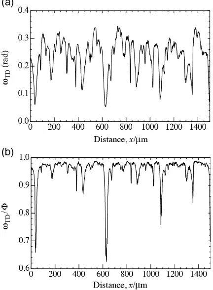
From Fig. 5, we find qualitatively that the change of the crystal orientation after rolling is close to the rotation around TD. This rotation around TD can be evaluated quantitatively by the log angles. The results are shown in Figs. 6 (a) and (b). In Fig. 6 (a), the horizontal and vertical axes show the dis-tance along a line parallel to RD and the variations of the log angles ωTD around TD respectively. In Fig. 6 (b), the
horizon-tal axis is the same as that in Fig. 6 (a), but the vertical axis shows the ratio of ωTD to the total rotation angle Φ. As shown
in Fig. 6 (b), the crystal orientation change in this case satis-fies ωTD/Φ > 0.9 at most of the measurement points.
Howev-er, we can also find that there are some points where ωTD/Φ
is small. These are important information to discuss arrays of dislocations and deformation structures after rolling. We will consider such experimental results using the log angles and discuss the mechanism of deformation structures.
5. Conclusions
The three-dimensional orthogonal rotation matrix R is im-portant to consider a crystal orientation with respect to a ref-erence frame. The logarithm of R, lnR is a skew symmetric tensor with three independent elements of real numbers. In the present study, we have shown by the goniometer-stage model that the three independent elements of lnR called the log angles are the sums of the divided rotation angles around the coordinate axes. Different from the Euler angles, the log angles are uniquely determined for certain R and considered to be the characteristic angles of R.
REFERENCES
1) N. Hansen: Metall. Mater. Trans. A 32 (2001) 2917–2935. 2) W. Pantleon: Acta Mater. 46 (1998) 451–456.
3) W. Pantleon: Scr. Mater. 53 (2005) 757–762.
4) J.A. Wert, Q. Liu and N. Hansen: Acta Mater. 45 (1997) 2565–2576. 5) J.A. Wert: Acta Mater. 50 (2002) 3125–3139.
6) Q. Liu, J. Wert and N. Hansen: Acta Mater. 48 (2000) 4267–4279. 7) U. F. Kocks, C. N. Tomé and H. -R. Wenk: Texture and Anisotropy,
(Cambridge University Press, Cambridge, 2000) pp. 57–77.
8) Q. Liu, C. Maurice, J. Driver and N. Hansen: Metall. Mater. Trans. A 29 (1998) 2333–2344.
9) M. Saito: Senkeidaisuugaku Nyumon (Introduction to linear algebra), (University of Tokyo Press, Tokyo, 1984) pp. 203–223.
10) P. Lancaster and M. Tismenetsky: The Theory of Matrices, Second Edi-tion with ApplicaEdi-tions, (Academic Press, San Diego, 1985).
11) R.A. Horn and C.R. Johnson: Topics in Matrix Analysis, (Cambridge University Press, Cambridge, 1994).
12) A. Yoshida, Y. Miyajima and S. Onaka: J. Jpn I. Met. 77 (2013) 435– 439.
13) A. Yoshida, Y. Miyajima, S. Onaka: J Mater. Sci. 49 (2014) 2013–2017. Fig. 5 Results of orientation analysis of a Cu single crystal before and after
rolling. White triangles show {111} pole figures before rolling. Black dots show {111} pole figures after 15% rolling obtained by scanning along a line parallel to RD in a central region of the rolled specimen.
[image:5.595.95.252.70.213.2] [image:5.595.319.535.73.367.2]14) S. Onaka, T. Hirose, H. Kato and S. Hashimoto: J. Japan Inst. Metals. 61 (1997) 574–579.
15) H. Grimmer: Acta Cryst. A 40 (1984) 108–112. 16) S. Onaka: J. Japan Inst. Metals. 74 (2010) 165–170. 17) S. Onaka: Philos. Mag. Lett. 90 (2010) 633–639. 18) S. Onaka: Philos. Mag. 92 (2012) 2264–2271. 19) S. Onaka: Mater. Trans. 53 (2012) 1547–1548.
Appendix
A1: Change in the logarithm lnλp of scalar λp
We first consider the change in the scalar λp as a function
of the time t assuming that λp is always positive and
continu-ous. When the change in λp during the infinitesimal time
in-terval δt is δλp, the rate νλ is given by
vλ=dλp/dt≈δλp/δt. (A1)
On the other hand, when we are interested in the normalized change δλp/λp instead of the change δλp itself, it is necessary
to consider the rate νn given by
vn=(dλp/dt)/λp=vλ/λp.
As shown by the following equation, the rate νn can be
re-garded as the rate of the logarithm lnλp : d(lnλp)
dt =
d(lnλp) dλp
dλp dt =λp−
1dλp dt =
vλ
λp =vn. (A2)
Hence, in order to consider the variation in the normalized λp,
the variation in the logarithm lnλp should be discussed.
A2: Logarithms of rotation matrices
We next consider the logarithms of rotation matrices. When the rotation angle is θ, the two-dimensional rotation matrix
R2D is written as
R2D= cossinθθ −cossinθθ . (A3)
When the rotation angle θ changes continuously as a function of the time t, the rate of R2D is given by differentiating the
elements of R2D with respect to t: dR2D
dt =
dθ
dt −
sinθ −cosθ
cosθ −sinθ . (A4)
For the scalar λp, the reciprocal λp−1 appears in calculations to
obtain the variation in lnλp, as shown in the third-side of
eq. (A2). In the case of matrix, its reciprocal corresponds to the inverse matrix. Hence, for the matrix R2D, by using the
inverse matrix R2D−1 written as
R2D−1= −cossinθθ cossinθθ (A5)
and eq. (A4), the matrix version of eq. (A2) is written as
R2D−1dRdt2D =dRdt2DR2D−1= dtd 0θ −0θ . (A6)
The two matrixes R2D−1 and dR2D/dt are commutative as
shown by calculating the products. The third side of eq. (A6) is the time derivative of the logarithm lnR2D given by eq. (8).
This means that the first and second sides of eq. (A6) give the variation in lnR2D. These sides have a form essentially the
same as that of the third side of eq. (A2) for the scalar λp.
The logarithm of the three-dimensional rotation matrix R is also given in a similar manner. Using eq. (9), the inverse matrix of R is written as
R−1=
(1−h2) cosΦ+h2 hk(1−cosΦ)+lsinΦ hk(1−cosΦ)−lsinΦ (1−k2) cosΦ+k2 lh(1−cosΦ)+ksinΦ kl(1−cosΦ)−hsinΦ
lh(1−cosΦ)−ksinΦ
kl(1−cosΦ)+hsinΦ (1−l2) cosΦ+l2
(A7)
When Φ changes as a function of t for fixed V = (h, k, l), dR/
dt is given by
dR dt =
dΦ dt
−
(1−h2) sinΦ hksinΦ−lcosΦ hksinΦ +lcosΦ −(1−k2) sinΦ
lhsinΦ−kcosΦ klsinΦ +hcosΦ
lhsinΦ +kcosΦ
klsinΦ−hcosΦ −(1−l2) sinΦ
.
(A8)
From eqs. (A7), (A8) and (10), we have the following equa-tion which is essentially the same as eq. (A6):
dR dtR−
1=R−1dR dt =
dΦ dt
0 −l k
l 0 −h
−k h 0