Evaluation of Tensile Properties of SiC/SiC Composites
with Miniaturized Specimens
Takashi Nozawa
1;*, Yutai Katoh
2and Akira Kohyama
1 1Institute of Advanced Energy, Kyoto University, Gokasho, Uji, Kyoto 611-0011, Japan
2Metals and Ceramics Division, Oak Ridge National Laboratory, Oak Ridge, TN 37831, USA
Mechanical testing after neutron irradiation is a critical research tool for evaluating materials for fusion systems, such as silicon carbide fiber silicon carbide matrix (SiC/SiC) composites. However, single-axis tensile testing, which is required to build a fundamental database, requires large specimens. Therefore miniaturization of tensile test specimens has long been pursued as a method to reduce the irradiation volume to fit the capsule size limitation. The objective of this study is to identify specimen size effects on tensile properties of SiC/SiC composites from the viewpoints of the influences of fabric architecture and tensile loading axis, with a final goal to establish a small specimen test technique for tensile testing of the composites. The axial fiber volume fraction plays an important role in achieving good tensile properties. However the size dependent change of the axial fiber volume fraction gives specimen size effect. The composites with much fiber volume content tended to have superior tensile strength, elastic modulus and proportional limit stress. Contrarily, the tensile properties of the composites with the same axial fiber volume fraction were almost independent of the specimen size. This type of size effect is generally common in any types of architecture. The size-relevant fracture mode in off-axis tension: detachment in shorter widths vs. in-plane shear at larger widths, also gives specimen size effect on tensile properties, resulting in strict limitation of miniaturization of the tensile specimen. Finally we proposed a miniature tensile specimen for the composites.
(Received September 21, 2004; Accepted February 15, 2005)
Keywords: ceramic matrix composites, small specimen test technique, size effect, tensile testing
1. Introduction
SiC/SiC composites are candidate materials for fusion blankets due to elevated temperature capability, low radio-activity, and inherently good neutron irradiation tolerance.1,2) Mechanical testing after neutron irradiation is a major requirement in the research for fusion-grade SiC/SiC composites. The flexural test has long been employed for evaluation of neutron irradiated materials. However, the complex fracture mode in flexure: mixture of tension, compression and shear, limits this test to screening purposes only. Simple fracture mode tests: loading in tension and shear, are therefore receiving more recent attention. Single-axis tensile test is a useful and fundamental test methodology with a simple fracture mode. However, there is no established tensile test technique for irradiation research on ceramic matrix composites (CMCs). The strict requirement of the comparatively large specimens in conventional tensile testing prevents use in neutron irradiation experiments because of the irradiation volume limitations. For this purpose, a small specimen test technique has been developed as a simple and useful testing method in the series of the international standardization activities.3,4) Miniaturization is an effective
means to evaluate irradiated materials because of the reduced radiological hazard potential. Small size also allows an increase in the test numbers, beneficial to statistical reli-ability. In addition, the small specimen test technique is required to give maximum use of the lab-scale products with very limited material volumes.
The ASTM standard C1275, familiar as a tensile testing methodology of the composites, provides various types of standard specimens with differed sizes and geometries.
Composite materials are composed of the constituent fiber, matrix and the fiber/matrix (F/M) interphase, each with finite scale. Therefore the specimen size of the composites is often determined by the constituent such as a fiber bundle composite. The ASTM standard specimens contain almost 48–120 bundles in the gauge section, considering the fiber bundle with 1.5 mm width and 0.25 mm thickness. A tensile specimen with<10fiber bundles in the gauge section is our recent goal to meet irradiation capsule requirements. How-ever miniaturization of the specimen must not spoil the inherent feature obtained from the characteristic composite architecture. This is because the composite strength is strongly dependent on the submicron-order constituents, giving rise to specimen size effects.
Specimen size effects of the composites have been investigated by both experimental and analytical ap-proaches.5–16)Specifically the recent attention is paid on the following factors: (1) inside sub-micron flaws, (2) micro-structure, (3) stress gradient and (4) test considerations. This technique cannot be established understanding of the influ-ence of theses factors.
Sub-micron flaws induced in processing and machining are primary factors that govern specimen size effects in ceramics and quasi-brittle materials. The most familiar relationship between the defects and their strength is the weakest link theory. The failure strength of a uniformly stressed volume of the brittle material is determined by the weakest defect, among defects randomly distributed in materials. Specifically the failure strength of the larger specimen tends to decrease because the probability of flaws increases with volume. This relationship of failure strength to specimen volume is well described by Weibull statistics.17) The global load sharing theory, based on the Weibull statistics, is often mentioned as a good analytical model to predict composite strength including the specimen scaling issue.5–7) This theory
hy-*Present address: Metals and Ceramics Division, Oak Ridge National
Laboratory, Oak Ridge, TN37831, USA
Special Issue on Fusion Blanket Structural Materials R&D in Japan
pothesizes that the redistribution of load is shared equally for all intact fibers when fibers progressively fail. In this hypothesis no stress concentration can occur. Under this hypothesis, the composite failure strength can be propor-tional to the axial fiber volume fraction. In contrast, the local load sharing theory assumes a non-uniform redistribution of load on the intact fibers.8,9) Under this condition, the stress
concentration around the broken fibers varies with the specimen size, resulting in another size effect. It is reported that failure strength decreases as laminate thickness decreas-es, due to increasing stress concentration.8,9)
The microstructure of the composites is also important in determining the defects that may give rise to a size effect. The constituent fibers and matrices themselves are subject to damage during processing and machining, producing the defects responsible for ultimate composite failure. Specifi-cally, degradation of the reinforcing fibers becomes a critical issue to achieving high fracture strength because the fibers must transfer almost all the applied load beyond first matrix cracking. Brittle fibers such as carbon and glass exhibit a strength size effect due to flaws in the microstructure of the fibers; tensile strength increases with reduced fiber diameter and gauge length, respectively.10,11) Fabric architecture is
also important to discuss mechanical properties of the composites. The multi-dimensional weave can easily create pockets where voids can be trapped or cracks can initiate. Stitched composites have another set of defects built into their microstructures. The stitching damages fibers and the stitches themselves form defects where cracks can initiate. The increasing defects raise the probability of composite failure. In particular, these origins of the failure initiation are dependent on the specimen size, because the architecture is strictly restricted by the constituents with a finite size. The fabric architecture also provides anisotropy of the compo-sites. Silicon carbide fiber reinforced composites exhibit anisotropic fracture behavior due to their discontinuous fabric structure. (The SiC fiber itself never shows anisotropy of fracture strength since the fibers have an isotropic microstructure.) In general, tensile strength tends to decrease with an increase in the angle between the fiber longitudinal direction and the loading direction, because the resulting reduction of the axial fiber volume fraction adds the shear failure at the F/M interface.
A stress gradient is another factor that governs the specimen size effect. In many tests, the stress field is not constant. For example, in flexure there is a stress gradient through the thickness. It has been shown theoretically from the Weibull theory that the strength in flexure should be higher than the strength in tension.12) The redistribution of
load that occurs as fibers progressively fail may produce a higher strength in flexure than in pure tension.13)The effect of
the stress gradient on failure has also been used to explain the variation in tensile strength of the notched composites as a function of the notch size.14) Moreover, the stress gradient
will affect the stress field during compressive loading. The compressive failure is in general caused by shear instability, often referred to as microbuckling. The stress gradient will affect the stress field where instability occurs.15,16)
Testing considerations are important technical issues in discussion of the specimen size effect issue. As mentioned
previously, different test methods can give rise to other size effects. Even if the same test method is employed, differences in the thickness and the aspect ratio of the specimens can provide premature failures due to unexpected bending moment produced by misalignment. Moreover early failure due to stress concentration near the grips may mask a size effect.
In order to discuss mechanical properties of the compo-sites, the influence of the tensile loading axis is specifically recognized as an important issue because of anisotropic features of the composites. The objective of this study is to evaluate specimen size effect on the tensile properties of the various architecture types of SiC/SiC composites by varied-axis tensile tests.
2. Experimental
2.1 Materials
Specimen size effects on tensile properties were evaluated using SiC/SiC composites fabricated by the polymer impregnation and pyrolysis (PIP) process. Three types of composites were produced: a plane-weave (P/W) composite, an eight-harness satin-weave (S/W) composite and an orthogonally woven three-dimensional (3D) composite. Both P/W and S/W SiC/SiC composites hadZ-directional fiber stitching. The ratio of the fabric configuration of 3D SiC/SiC composite wasX:Y:Z ¼1:0:1:0:0:2. HereXandY mean the fiber longitudinal direction, while Z means the through-thickness direction. Typically these composites had relative-ly high porosity above 20%. They exhibited several large pores inside the structure, primarily along theZ-stitches. The Tyranno-LoxM (Si–Ti–C–O) fibers used as reinforcements had undergone a surface modification before weaving in order to optimize the fiber-matrix interface.18) Due to this
treatment, an interphase with excess carbon was formed close to the fiber surfaces. Details of materials are described elsewhere.19,20)
2.2 Tensile Test
Room-temperature tensile tests were carried out using a face-loaded rectangular tensile specimen (Fig. 1) following the method of ASTM C1275. The main reason to use
straight-Constants Valuables
15.0Lx3.0W(All) T=1.0, 1.5, 2.0, 2.5, 3.0
15.0Lx3.0T (P/W & S/W) 15.0Lx2.0T, 15.0Lx3.0T(3D) W=1.5, 3.0, 6.0, 9.0
3.0Wx3.0T (P/W & S/W)
2.0Wx2.0T, 3.0Wx2.0T, 3.0Wx3.0T(3D) L=5.0, 15.0, 30.0, 45.0
Fiber longitudinal direction
X (loading axis) Y
θ =0, 15, 30, 45°
L L+60
W
(Units: mm) Thickness: T
[image:2.595.307.548.600.755.2]sided geometry is to prevent from the accumulation of undesired machining flaws and also to avoid stress concen-tration at the root of these flaws. All tensile specimens were machined using a diamond cutting device and machined surfaces were polished to a surface roughness of5mmto reduce machining flaws. The fiber direction was parallel to the tensile loading axis for the axial tensile test or rotated off 15, 30and 45for the off-axis tensile test. For simplicity, we denote them as [0/90], [15/75], [30/60] and [45/ 45], respectively. The gauge size of each specimen was designed by the number of fiber bundles included in the cross-section. At least one bundle (1:5mm/bundle) in width and four bundles (0:25mm/bundle) in thickness were included. Specimen gauge length was determined on the basis of total specimen length, 15–45 mm (10–30 bundles), which is expected for neutron irradiation tests. The straight-sided ASTM standard specimen with the gauge volume of
L30W6T3mm3 (total size: L100W6T3mm3) was
used for comparison in the fiber longitudinal axis test. No standard specimen was used in the off-axis tests due to very limited volume of the supplied composites. All tensile specimens were clamped by wedge-typed grips, and to avoid gripping damage, 1.0 mm thick aluminum end tabs were bonded on both sides of the specimen. Crosshead displace-ment rate was 0.5 mm/min for all tests. The strain of the composites was measured by averaging two readings of strain gauges bonded to both faces of the center gauge section. After tensile tests, fracture surfaces were analyzed by optical and scanning electron microscopy to investigate the fracture mechanism.
3. Results
3.1 Tensile Properties in Fiber Longitudinal Axis Figure 2 shows typical tensile behaviors of P/W, S/W and
3D SiC/SiC composites. All types of SiC/SiC composites exhibited non-linear segment beyond proportional limit due to progressive accumulation of matrix cracks. Less elonga-tion for P/W composites (0.4–0.7) and S/W composites (0.4–0.6) was attributed to the structural restrictions caused by weaving fiber bundles. Fracture surfaces for P/W SiC/SiC composites showed fibrous appearances although they failed with shorter fiber pullout lengths (Fig. 3). In contrast, 3D SiC/SiC composites exhibited much longer fiber pullout because of less restriction to the total elongation due to straightly aligned fibers parallel to the loading direction. Specifically fiber bundle pullout was characteristic in 3D SiC/SiC composites. These failure patterns are almost kept in entire tested specimen size range. For example, no significant difference in tensile fracture appearances was observed for 3D SiC/SiC composites with varied widths
0 100 200 300 400
0 0.5 1 1.5 2
Strain,
Tensile Stress,
P/W [0°/90°]
3D [0°/90°]
P/W [45°/45°]
3D [45°/45°] S/W [0°/90°]
ε / %
σ
/ MPa
Fig. 2 Typical tensile stress–strain curves of P/W, S/W and 3D SiC/SiC composites.
500
µ
m
50
µ
m
(a) 2D (P/W)
50
µ
m
500
µ
m
(b) 3D
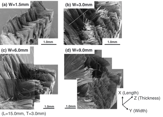
[image:3.595.313.541.73.239.2] [image:3.595.127.469.508.770.2](Fig. 4). The only exception of the stress concentration around stitching fibers is important in the 1.5-mm-wide case for 3D SiC/SiC composites. A large stress concentration should arise along the detached Z-stitches, resulting in premature failure of the composites because the stitching
[image:4.595.47.278.81.323.2]fibers perpendicular to the loading direction do not transfer load once detachment occurs at the F/M interface.
Figure 5 exhibits specimen size effects on tensile strength, elastic modulus and proportional limit stress (PLS). Tensile results with percent bending larger than 5% were not included in this figure. Upper and lower error bars in the plots indicate the maximum and minimum values, respec-tively. Tensile strength of both P/W and S/W composites was nearly independent of the specimen size in the entire tested range, while the tensile strength of the 3D composites was significantly dependent on the specimen length, width and thickness: increased tensile strength for the composites with the gauge size ofL15W3T1:5,L15W3T2and
L15W3T3mm3. In contrast, elastic moduli of both 2D
and 3D composites were nearly independent of the specimen size. The only exception was obtained for the 5.0-mm-long 3D composites; where the tensile modulus decreased30%. The 2D composites did not exhibit significant size effects on tensile modulus. Similarly, the PLS was apparently inde-pendent of specimen gauge length, width and thickness for both 2D and 3D SiC/SiC composites. However, there was significantly large scatter in the smaller gauge volume, especially for small gauge width (<3:0mm) 3D composites. Tensile properties obtained from the standard specimen were almost followed by these trends.
3.2 Tensile Properties in Varied Loading Axis
Figure 2 also shows typical off-axis tensile behaviors of P/ W and 3D SiC/SiC composites. Stress–strain curves for all materials were mostly non-linear except for a very short linear region in the initial stage of the curves. Proportional
5.0 mm
1.5 mm in Width
3.0 mm in Width
6.0 mm in Width
9.0 mm in Width
(Length: 15.0mm, Thickness: 2.0mm)Fig. 4 Tensile fracture appearances of 3D SiC/SiC composites with varied gauge widths.
100 200 300 400 500 600
50 100
0 20 40 60 80
0 10 20 30 40
Gauge Length, L/ mm
4
Gauge Width, W / mm
3 Gauge Thickness, T/ mm
3D (3Wx3T)
3D (3Wx2T)
3D (2Wx2T)
3D-std. (6Wx3T)
0 0
3D (15Lx3W)
3D-std. (30Lx6W)
P/W (15Lx3W)
P/W-std. (30Lx6W) 3D (15Lx3T)
3D (15Lx2T)
3D-std (30Lx3T)
P/W (3Wx3T)
P/W-std. (6Wx3T)
S/W (3Wx3T)
S/W-std. (6Wx3T)
P/W (15Lx3T)
P/W-std. (30Lx3T)
S/W (15Lx3T)
S/W-std. (30Lx3T)
S/W (15Lx3W)
S/W-std. (30Lx6W)
Proportional Limit Stress,
mc
/ MPa
Elastic Modulus, E / GPa
Tensile Strength, s
/ MPa
0 2 6 8 0 1 2 4
σ
σ
[image:4.595.99.495.455.755.2]limit stress and elastic modulus were very low due to anisotropy of the composites. Beyond proportional limit, accumulation of the strain was quite different between [0/ 90] and [45/45] SiC/SiC composites. The latter trans-ferred the load primarily by interfacial shear stress. Low stiffness of interfacial deformation resulted in progressive strain accumulation at the lower stress level. Tensile fracture behavior of the [15/75] and [30/60] composites were very similar to that of the [45/45] composites.
Figure 6 shows typical fracture surfaces of the off-axis tensile specimens for P/W SiC/SiC composites. In general, all specimens exhibited a V-shaped fracture plane. Specif-ically most fibers of the specimens with shorter gauge widths were remained as intact. The detachment of the F/M interface was characteristic in these composites. In contrast, the specimens with larger widths (>6:0mm) incorporated with fiber failure and interfacial detachment. The 3D composites also exhibited the similar trend. Contrarily, there is no significant difference in fracture behaviors of the specimens with differed lengths or thicknesses (with constant width) for both P/W and 3D composites.
Figure 7 shows the effects of the specimen size on tensile properties of P/W and 3D PIP SiC/SiC composites for various directional loading tests. Tensile strength and PLS decreased with increasing specimen widths for 2D and 3D composites, although they never show significant length or thickness effects. The elastic modulus was hardly dependent on the specimen length, width and thickness. However severe degradation was obtained for the 1.5 mm wide specimen in the [15/75] loading test of 3D composites.
4. Discussion
4.1 Specimen Size Effect on Tensile Properties in Fiber Longitudinal Axis
In the ideal composite system, the tensile strength in the
fiber longitudinal direction is proportional to the axial fiber volume fraction.5)This relation should hold true for 2D and 3D composite systems because the longitudinal fibers acting alone can transfer the entire load following first matrix cracking. We obtained a good relationship between the axial fiber volume fraction and the tensile strength regardless of the specimen size (Fig. 8). The large uncertainity of the axial fiber volume fraction in a 3D structure can be easily obtained by imaging its structural unit cell18)(Fig. 9). The presence of
theZ-stitches can separate a fiber rich region or a matrix rich region using specimens smaller than a structural unit width of 2:0mm, resulting in the large scatter of axial fiber content. Similarly, the axial fiber volume fraction is also subject to variation within the specimen thickness. However, there might be a minor effect on the tensile properties in cases where the specimen thickness is large enough to cover many fiber bundles. The axial fiber volume fraction was nearly same through entire thickness range. In contrast, the tightly woven P/W and S/W composites can cause a small change of the axial fiber volume fraction with respect to the specimen width and thickness.
Here we defined a new parameter: normalized tensile strength, which is the maximum tensile stress divided by the axial fiber volume fraction. Normalized tensile strength means the stress where the entire load is applied only to the axial fibers. This new parameter will be good to evaluate the behavior after the first matrix cracking of the composites. Figure 10 plots the specimen width effect on normalized tensile strength. This revealed no width effect for widths >3:0mm and no thickness effect for >1:5mm, although a slight reduction (30%) of normalized tensile strength was seen in shorter gauge widths or thicknesses. There is also no apparent length dependence in the range tested. A slight decrease in the tensile strength of 1.5-mm-wide and 1.0-mm-thick specimens might be explained by the influence of machining damage on the bare fibers near the specimen 1.0mm
1.0mm
1.0mm 1.0mm
(b) W=3.0mm
(L=15.0mm, T=3.0mm)
Z (Thickness) X (Length)
Y (Width) (a) W=1.5mm
(d) W=9.0mm (c) W=6.0mm
[image:5.595.129.473.72.318.2]surfaces. Discontinuous fibers are ineffective to transfer the applied load. Actual volume fraction of the intact fibers was probably smaller than that used in normalization. Otherwise this might be explained by the local load sharing analysis, although further investigation is required. Recently exper-imental and numerical analyses have been developed to evaluate this phenomenon.8,9)
Tensile elastic modulus of the 3D composites is also estimated by the simple analytical model based on the rule of mixtures.18) This indicates that the tensile elastic modulus exhibits monotonic increase with the axial fiber volume fraction increasing.19,20)As similar to tensile strength, tensile
elastic modulus exhibited large scatter in the gauge width of 1.5 mm. Figure 11 plots measured and predicted axial elastic moduli relevant to the axial fiber volume fraction for 3D PIP SiC/SiC composites. The size-related change of the axial fiber volume fraction will possibly affect elastic modulus, although this effect might be small. The primary mechanism
3D [15°/75°] 3D [30°/60°]
3D [45°/45°] P/W [45°/45°]
50 100 150 200
20 40
0 10 20 30
0 10 20 30 40
Gauge Length, L / mm
4 8
Gauge Width, W / mm
2 4
1 3
Gauge Thickness, T / mm Proportional Limit Stress,
mc
/ MPa
Elastic Modulus, E/ GPa
Tensile Strength,
s
/ MPa
σ
σ
0 2 6 0
0 0
(W=3mm, T=3mm) (L=15mm, T=3mm) (L=15mm, W=3mm)
Fig. 7 Off-axis tensile properties of P/W and 3D SiC/SiC composites with varied specimen width. Upper and lower error bars in the plots indicate the maximum and minimum values, respectively.
0 200 400 600 800
10 15 20 25 30
Axial Fiber Volume Fraction, fx / vol%
15Lx1.5Wx2T 15Lx3Wx2T 15Lx6Wx2T 15Lx9Wx2T 15Lx3Wx1T 15Lx3Wx1.5T 15Lx3Wx2.5T 15Lx3Wx3T 5Lx2Wx2T 30Lx3Wx2T 45Lx3Wx2T
Tensile Strength,
s
/ MPa
σ
Fig. 8 Effect of the axial fiber volume fraction on tensile strength of 3D PIP SiC/SiC composites.
a
b
c
d
e
h
h
2 1
x
y
z
I
II
III
[image:6.595.98.497.74.357.2] [image:6.595.51.291.414.592.2] [image:6.595.307.547.415.659.2]that causes the reduced tensile modulus for the 5.0-mm-long specimen might be due to width effect typical for the short width (2:0mm) specimen.
Proportional limit stress also shows a function of the axial fiber volume fraction.21)According to the analytical model prediction, PLS tends to monotonically increase with increasing fiber content. However the quantitative analysis indicates that the average PLS was constant regardless of the axial fiber volume fraction (Fig. 12), but with very large scatter of individual data. The difference comes from the large scatter of other parameters, which might mask the specimen size effect on PLS.
4.2 Specimen Size Effect on Tensile Properties in Varied Loading Axis
Off-axis tensile tests of the composite materials resulted in low fracture stress and high elongation compared to the axial tensile tests. In this case, the composite failure was significantly dependent on the detachment strength between fiber and matrix rather than only on the tensile strength of fibers. This is apparently true according to fracture surfaces. The V-shaped fracture appearance was characteristic of each
surface. In-plane shear strength calculated from the off-axis tensile data converged to a constant with increasing specimen gauge widths (Fig. 13). In contrast, the in-plane shear strength obtained by Iosipescu shear test shows no size dependency.22) Iosipescu shear test is one of the testing
methods to evaluate the in-plane shear properties of ceramics and composites. This test provides pure shear stress field between two notches curved on both sides of the specimen. These results indicate that the key fracture mechanism in off-axis tension had a different dependence on specimen width because of the presence of several simultaneous failure modes. In general, three kinds of stresses; tensile stress in the longitudinal fiber direction, transverse tensile stress perpen-dicular to the longitudinal fiber direction and in-plane shear parallel to the fibers, are active during off-axis tensile loading. In shorter widths, the off-axis tensile strength might be determined by the weak detachment strength at the F/M interface rather than by fiber tension and in-plane shear. This 0 500 1000 1500 2000 2500 3000 3500
0 10 20 30 40 50
Gauge Length, L / mm
0 500 1000 1500 2000 2500 3000 3500
0 2 4 6 8 10
Gauge Width, W / mm
0 500 1000 1500 2000 2500 3000 3500
0 1 2 3 4
Gauge Thickness, T / mm Normalized Tensile Strength,
s / f σ x / MPa (a)
Normalized Tensile Strength,
s / f σ x / MP a
Normalized Tensile Strength,
s / f σ x / MPa (b) (c)
3D (3Wx3T)
3D (3Wx2T)
3D (2Wx2T)
3D-std. (6Wx3T)
3D (15Lx3W)
3D-std. (30Lx6W)
P/W (15Lx3W)
P/W-std. (30Lx6W)
3D (15Lx3T)
3D (15Lx2T)
3D-std (30Lx3T)
P/W (3Wx3T)
P/W-std. (6Wx3T)
S/W (3Wx3T)
S/W-std. (6Wx3T)
P/W (15Lx3T)
P/W-std. (30Lx3T)
S/W (15Lx3T)
S/W-std. (30Lx3T)
S/W (15Lx3W)
[image:7.595.306.547.75.250.2]S/W-std. (30Lx6W)
Fig. 10 Effects of specimen (a) length, (b) width and (c) thickness on normalized tensile strength, defined as tensile strength divided by the axial fiber volume fraction. Upper and lower error bars in the plots indicate the maximum and minimum values, respectively.
0 50 100 150
10 15 20 25 30
Axial Fiber Volume Fraction, fx / vol%
Elastic Modulus,
E
/ GPa
15Lx1.5Wx2T 15Lx3Wx2T 15Lx6Wx2T 15Lx9Wx2T 15Llx3Wx1T 15Lx3Wx1.5T
15Lx3Wx2.5T 15Lx3Wx3T 5Lx2Wx2T 30Lx3Wx2T 45Lx3Wx2T
[image:7.595.55.281.77.448.2]Em=10 Em=20 Em=30
Fig. 11 Effect of the axial fiber volume fraction on tensile elastic modulus of 3D PIP SiC/SiC composites. Fitting curves were estimated by eq. (7) in ref. 19 using characteristic lengths, a¼b¼1:25mm, c¼0:75mm, d¼e¼0:37mm,h1¼h2¼0:25mm, fiber volume fraction of a fiber
bundle composite,f ¼0:7, and elastic moduli of the fiber and the matrix, Ef¼187GPa andEm¼10{30GPa, respectively.
0 20 40 60 80 100 120
10 15 20 25 30
Axial Fiber Volume Fraction, fx / vol%
15Lx1.5Wx2T 15Lx3Wx2T 15Lx6Wx2T 15Lx9Wx2T 15Lx3Wx1T 15Lx3Wx1.5T 15Lx3Wx2.5T 15Lx3Wx3T 5Lx2Wx2T 30Lx3Wx2T 45Lx3Wx2T
Proportional Limit Stress,
mc
/ MPa
σ
[image:7.595.308.547.343.521.2]is because the lack of cross-weave enables the F/M interface to detach easily. In contrast, in larger widths (>6:0mm), the composites strength should be determined by in-plane shear mode fracture, although the interfacial detachment mode may still operate. Moreover, in [15/75] loading tests, a tensile failure mode as well as the in-plane shear and detachment failure modes might also operate in the larger width range.
Elastic modulus of the off-axis tensile test is determined by considering tensile elastic deformation of the fibers and the matrix in both fiber longitudinal and radial directions, and in-plane shear deformation at the F/M interface. Fiber volume content in the gauge section becomes a constant in the off-axis loading test regardless of the gauge size for all composite types. In-plane shear modulus is also independent of the specimen size because of no microscopic change at the F/M interface. Therefore the meaning size effect was hardly obtained. The primary reason to the reduced elastic modulus for the 1.5 mm-wide specimen of [15/75] 3D composites is probably due to mechanical damage during machining but still unclear.
As discussed, the off-axis tensile specimens were failed primarily by detachment and/or in-plane shear fracture mode. The only detachment at the F/M interface is a primary fracture mode for the narrow specimen. At the crack initiation, most cracks propagated along the F/M interface. It is reported that push-out test results indicate that the interfacial debonding shear strength first increases and converges into a constant with the increasing axial lengths (specimen thickness).23)This can explain the slight reduction
of PLS for short width specimens. Another possible explan-ation for the reduced PLS in shorter widths is machining damage on the F/M interface. Detachment strength is usually very weak comparing fiber strength and/or in-plane shear strength of the woven composites. The weak detachment strength provides significantly lower off-axis tensile strength. Under the single fracture mode tests (length and thickness effect tests), no size effect was detected.
4.3 Generality of Specimen Size Effect
The effects of the axial fiber volume fraction on tensile
properties are common in most types of composites. A recent study revealed the width effect on tensile strength of various types of SiC/SiC composites.24) In that report, a three
directionally woven Tyranno-SA fiber reinforced compo-site made by the modified PIP process25)and a cross-plied
Tyranno-SA fiber reinforced laminate composite made by the nano-infiltration transient eutectic phase (NITE) proc-ess26,27) were evaluated. Both composites featured a highly
crystalline and near stoichiometric SiC matrix. Specifically the NITE SiC/SiC composite provides a robust structure and dense matrix (3:1g/cm3). In 3D advanced PIP SiC/SiC, the axial tensile properties depended significantly on the cross-sectional fiber volume content similar to the case of 3D PIP SiC/SiC composites. In contrast, the cross-plied laminate NITE SiC/SiC composites had no width effect on tensile properties because the axial fiber content is constant in any specimen widths under the same thickness due to the lay-up structure of the unidirectional fiber bundle composites.
4.4 Miniature Specimen
Not all CMCs follow the Weibull theory, due to the presence of multiple fracture modes, even though the constituent materials are brittle ceramics. We identified significant width effect on tensile strength, tensile elastic modulus and PLS. They are closely dependent on the axial fiber volume fraction and differed in specimen widths. Data scatter tended to increase in shorter gauge widths. In general, these data are adequately normalized by simple model prediction using the fiber volume content for any size of the composites. However, strength reduction by the stitching effect needs to be avoided in shorter widths. In conclusion, specimen width is recommended to be 3.0–4.0 mm to include a couple of fiber bundles. In contrast, off-axis tensile strength is decreased in narrower gauge widths because of the size-related change of fracture mode from the mixed mode of in-plane shear to fiber detachment. Therefore specimen gauge width should be 6.0–10.0 mm or larger for off-axis tensile testing. Specimen thickness has a minor effect on tensile strength in the range of 1.0–3.0 mm. However, thinner specimens (<1:0mm) tend to decrease tensile strength, resulting in difficult testing in normal operation. Porous composites such as chemical vapor infiltrated (CVI) SiC/SiC composites contain many submicron inter-laminar pores; for those we do not recommend using test specimens thinner than 1.0 mm. Specimen thickness of 1.5–2.0 mm is recommended to reduce the irradiation volume. No meaningful length effect, which was found in tensile strength in 30.0–50.0 mm-long specimens with 15.0–20.0 mm gauge length under the constant axial fiber volume fraction, is a great advantage to design the miniature specimen.
No significant effect of the specimen size resulted in unique tensile strength, elastic modulus and PLS, which were well agreed with those obtained from standard size specimen. In short, the miniature specimens used in this study can predict the mechanical properties of the bulk composites. The systematic size effects on the off-axis tensile properties can also utilize to evaluate the bulk properties of the composites, although no standard data were obtained. Specifically the key mechanism of the specimen size effect might be remained for the composites tailored by small fiber bundles; the tensile
0 20 40 60 80 100
0 5 10 15
Gauge Width, W / mm
In-Plane Shear Strength,
IPSS
/ MPa
τ
Iosipescu shear:
[45°/45°] tension:
P/W, 3D
P/W, 3D
[image:8.595.49.289.73.238.2]Off-axis tension Iosipescu shear
properties are easily predicted by considering the minimum structural unit, in many cases fiber bundles, and its config-uration. Therefore, much smaller specimen can be adopted to utilize. However, machining damage needs to be avoided to keep a good mechanical performance. Their tensile proper-ties are more subject to these defects.
5. Summary
Development of mechanical testing methodologies has been carried out. In order to establish a small specimen test technique for tensile testing of ceramic matrix composites, specimen size effects on tensile properties were investigated from the viewpoint of architecture and varied loading directions. The main conclusions are summarized as follows. (1) The axial fiber volume fraction plays an important role in achieving good tensile properties, but the size dependent change of the axial fiber volume fraction gives specimen size effect on them. The composites with much fiber volume fraction tended to have greater tensile strength, elastic modulus and PLS. This type of size effect is generally common in any types of architecture.
(2) Both 2D and 3D SiC/SiC composites with the same axial fiber volume content hardly exhibited meaningful size effect on the tensile properties in the fiber longitudinal direction.
(3) The size-relevant fracture mode in off-axis tension: detachment in shorter widths vs. in-plane shear at larger widths, gives specimen size effect on the off-axis tensile properties, resulting in strict limitation of miniaturiza-tion of the tensile specimen.
(4) This study provides a promising approach to tensile testing using the miniature specimen for ceramic matrix composites.
Acknowledgements
The authors would like to thank Dr. Edgar Lara-Curzio at Oak Ridge National Laboratory for useful discussion. This work was performed as a part of ‘R&D of Composite Materials for Advanced Energy Systems’ research project supported by Core Research for Evolutional Science and Technology (CREST) and ‘Fundamental R&D on Advanced Material System for (High Efficiency
Environment-conscious) very High Temperature Gas-cooled Fast Reactor Core Structures’ by IVNET Program of MEXT, Japan.
REFERENCES
1) A. R. Raffray, R. Jones, G. Aiello, M. Billone, L. Giancarli, H. Golfier, A. Hasegawa, Y. Katoh, A. Kohyama, S. Nishio, B. Riccardi and M. S. Tillack: Fusion Eng. Des.55(2001) 55–95.
2) B. Riccardi, L. Giancarli, A. Hasegawa, Y. Katoh, A. Kohyama, R. H. Jones and L. L. Snead: J. Nucl. Mater.329–333(2004) 56–65. 3) W. R. Corwin, S. T. Rosinski and E. V. Walle:Small Specimen Test
Techniques, ASTM STP 1329 (American Society for Testing and Materials, PA, 1998).
4) M. A. Sokolov, J. D. Landes and G. E. Lucas:Small Specimen Test Techniques: Fourth Volume, ASTM STP 1418(ASTM International, West Conshohocken, PA, 2002).
5) W. A. Curtin: J. Am. Ceram. Soc.74(1991) 2837–2845. 6) M. Sutcu: Acta Metall. Mater.37(1989) 651–661. 7) W. A. Curtin: J. Am. Ceram. Soc.77(1994) 1072–1074.
8) M. Ibnabdeljalil and W. A. Curtin: Int. J. Solids Struct.34(1997) 2649– 2668.
9) W. A. Curtin: Compos. Sci. Technol.57(1997) 471–481.
10) A. A. Griffith: Phillos. Trans. R. Soc. London, Ser. A221(1920) 163– 198.
11) J. W. Hitchon and D. C. Phillips: Fiber Sci. Technol.12(1979) 217– 233.
12) J. C. McNulty and F. W. Zok: J. Am. Ceram. Soc.80(1997) 1535– 1543.
13) M. R. Wisnom: J. Compos. Mater.26(1992) 1173–1180.
14) R. T. Potter: Phillos. Trans. R. Soc. London, Ser. A361(1978) 325– 341.
15) M. R. Wisnom: J. Compos. Mater.28(1994) 66–76.
16) M. R. Wisnom and J. A. Atkinson: Composite A28(1997) 959–964. 17) W. Weibull: J. Appl. Mech.18(1951) 293–297.
18) T. Ishikawa, K. Bansaku, N. Watanabe, Y. Nomura, M. Shibuya and T. Hirokawa: Compos. Sci. Technol.58(1998) 51–63.
19) T. Nozawa, T. Hinoki, Y. Katoh, A. Kohyama, E. Lara-Curzio and M. Sato: Ceram. Trans.124(2001) 351–362.
20) T. Nozawa, T. Hinoki, Y. Katoh, A. Kohyama and E. Lara-Curzio:
ASTM STP1418(2002) 294–305.
21) A. G. Evans and F. W. Zok: J. Mater. Sci.29(1994) 3857–3896. 22) T. Nozawa, E. Lara-Curzio, Y. Katoh and A. Kohyama: Ceram. Trans.
139(2002) 127–138.
23) C.-H. Hsueh: Acta Metall. Mater.38(1990) 403–409.
24) T. Nozawa, Y. Katho, A. Kohyama and E. Lara-Curzio: Ceram. Eng. Sci. Proc.24(2003) 415–420.
25) T. Nozawa, K. Ozawa, Y. Katoh and A. Kohyama: Mater. Trans.45 (2004) 307–310.
26) Y. Katoh, S. M. Dong and A. Kohyama: Ceram. Trans.144(2002) 77– 86.