fabricate a crack-free joining of heterogeneous ceramics. To calculate three-dimensional thermal stresses of those fabricated FGM samples, a finite element analysis tool, ALGOR, was used. The Von Mises failure criterion and the maximum stress criterion were applied to predict failures in the FGM samples. For each case, calculated strength of each FGM layer by rule of mixture was compared with predicted thermal residual stresses. The Von Mises failure criterion predicted the locations of cracks more precisely than the maximum stress criterion. Such analyses are especially useful for graded FGM samples where the residual stresses are very difficult to measure experimentally.
[doi:10.2320/matertrans.MRA2007092]
(Received April 23, 2007; Accepted July 3, 2007; Published August 22, 2007)
Keywords: functionally grade material, finite element analysis, sialon, silicon nitride, polytypoid
1. Introduction
Concept of using functionally graded material (FGM) to the joining of materials is an important process commercially and technologically.1,2)The FGM bonding has a continuous change in one composition from one side to the other, with a corresponding compatible gradient of thermal expansion properties. The purpose of FGM is designed to take advantage of certain desirable features of each of the constituent phases. For a situation where FGM is used to separate regions of high and low temperature, pure ceramic needs to be located at the hotter end because of the better resistance to the higher temperatures. For the cooler end, metallic materials needs to be located for its better mechan-ical and heat-transfer properties. The possibility of using a graded junction allows a potentially effective joining of ceramics with widely differing Coefficients of Thermal Expansions (CTEs). This concept has been used successfully in sialon polytypoidal functional gradient joining of dissim-ilar ceramics, Si3N4and Al2O3, described in Ref. 3). Such a design allows a gradual change in thermal expansion mismatch, minimizing the thermal stresses arising from cooling or heating. Therefore, FGMs offer solution to the thermal stress problem and have created wide interest recently.4–9)
Since the thermal stresses need to be minimized in FGM research, several studies have focused on the theoretical and experimental assessment of these stresses in FGM.1)For a more general two-dimensional (2-D) or three-dimensional (3-D) problem, numerical methods such as a finite element analysis (FEA) are required. This concept has been used successfully in analyzing residual stresses in axisymmetric mode, as described in Ref. 10, 11).
In this paper, various FGM joints were processed and the
thermal stresses and failure for each sample were analyzed in 3-D using FEA program ALGOR12)to confirm experimental results. ALGOR is a finite element analysis program to calculate three-dimensional thermal stresses within FGM. Moreover, Von Mises failure criterion and maximum stress criterion were applied to predict failures, and this analysis results were compared with the fabricated samples.
2. Experimental
2.1 Material fabrication
To create FGMs, a ‘‘mixture rule’’ was applied to make the gradient since it has been widely used in the modeling of FGMs. A material having two components, denoted as A and B, is considered. Let PA and PB be the values of some particular property for pure A and pure B, respectively, and let their respective volume fractions be fA and fB, where
fB¼1fAassuming that the material is 100% dense. For an FGM, these values of f are dependent upon position along the graded direction. The well-known Voigt-type estimate for the effective value,P, of the property of FGM is
P¼ fAPAþfBPB ð1Þ
This ‘‘mixture rule’’ was applied to calculate CTE of each graded layer so that the final FGM with 18 graded layers would have a CTE difference of approximately0:2106/ C between each layer, to minimize residual stress.
FGM was fabricated by the following method; first, powders of each composition were mixed in isopropanol solvent, and then powders were agitated using the ultra-sonicator to prevent an agglomeration. Si3N4 powders from H. C. Starck with a particle size ranging from 0.4–1.2mm
for polytypoid powders.3) These powders were dried, and sieved and were stacked layer by layer. The green body was pressed using a cold press to maintain a cylindrical shape. The appropriate layers of powder mixes with various thicknesses were successively filled in a graphite hot-press die of 1 inch (2.54 mm) diameter to prepare the sample. The sample was subsequently hot-pressed at 50 MPa, at 1700C, for two hours, and then furnace-cooled to room temperature at 2C/min.3)Details of the processing and characterization methods are described by Lee et al.3) Optical micrographs were used to locate cracks at the cross section of the samples.
3. Finite Element Analysis
3.1 Calculation of residual stresses using FEA
The thermal stresses of this FGM geometry were computed taking into account of both CTE and modulus variation of the multitude of joining layers. These formulations do not contain an explicit reference to the microstructure of the FGM, but it can be assumed that the behavior of the composite can be calculated solely from the properties and volume fractions of the constituents. By using the effective properties of the FGM and by tracking the changes in the composition through the effective properties, the residual stress calculations are obtainable without specific micro-structural modeling. Moreover, since the actual residual-stress measurement and residual-stress analysis of this FGM sample are very difficult, the calculation using FEA will be beneficial to the majority of practical FGM material combinations.
The coordinates for the stress analysis of the cylindrical FGM specimens were defined as Fig. 1, and each 3-D FEA model was created according to the dimensions of each specimen. Figure 2 shows an example of the three-layer FEA model consisted of 4032 brick elements and 14140 nodes.
The residual stresses can be assumed to be generated at the cooling stage when sintered temperature of 1700C was dropped to 20C. Thus, 1680C drop of temperature was applied as the thermal loading to the ALGOR analysis for residual stresses calculations.
3.2 Failure criteria
Two failure criteria were applied to the experimental data
to explain failure of FGM layers: Von Mises criterion and maximum stress criterion.
The Von Mises failure criterion represents failure by maximum shear stress.
1
2fð12Þ
2þ ð
23Þ2þ ð31Þ2g
1
2
y ð2Þ
As shown in eq. (2), when the tensile yield strength (y) of
certain area of the sample reaches the left hand side of eq. (2), the material fails. For brittle materials like ceramic, ultimate tensile strength may substitute the tensile yield strength.
Maximum stress criterion compares each orthotropic component of stress obtained from analysis result with tensile strength of the material. If any component of stress exceeds strength, failure of structure is assumed.
4. Results and Discussion
4.1 Residual stress computations by Von Mises criterion
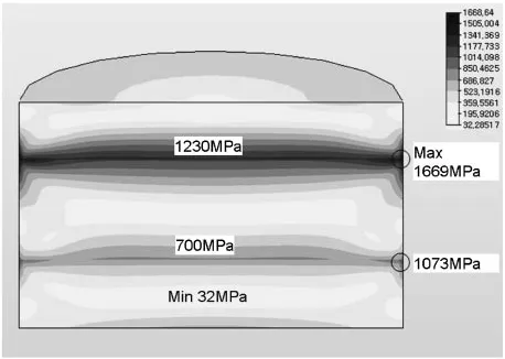
Figure 3 shows the cross section of the three-layer FGM with distribution of thermal residual stresses calculated by FEA. To compare the locations of cracks in each joint with
Fig. 1 Sample geometry and coordinate systems. Fig. 2 An Example of 3-D FE model (3 layers).
[image:2.595.56.286.71.248.2] [image:2.595.311.543.73.244.2] [image:2.595.312.541.293.456.2]the failed location by Von Mises stress, the maximum Von Mises stresses for each FGM layer and predicted strength of the layer were marked together as shown in Fig. 46.
For the three-layer FGM joint, a thick interlayer which has a similar thickness as two base materials was used in the middle. This thick interlayer was expected to relieve some of the strain energy that accumulated during the cooling process. However, the result in Fig. 4 showed that cracks were developed due to high residual stresses build up among the interfaces.
The Von Mises stresses by FEA were ranged from 32 MPa to 1669 MPa. The maximum Von Mises stress of Si3N4 (590 MPa) was slightly less than tensile strength of Si3N4 (595 MPa, Table 1) resulting in no cracks. However, max-imum stresses for polytypoid layer (1073 MPa) and Al2O3 layer (1669 MPa) were greater than these tensile strengths (455 MPa and 200 MPa respectively, Table 1). That
simu-lation matches experimental results as shown in Fig. 4 where cracks were developed only on polytypoid and Al2O3layers. Since adding a thicker layer did not resolve crack problems, grading layers were added between the joining materials to relieve residual stress, as shown in Figure 5. Although the gradient across the length of the joint was varied by 25 mass% increment in composition to make nine
Fig. 5 FGM joint between Al2O3and Si3N4with 25 mass% increment in composition (9 layer).
[image:3.595.126.471.76.172.2]Fig. 6 Final crack-free FGM (20 layer).
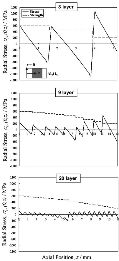
Table 1 Physical Constants for the materials used for ALGOR calculation.
Properties Si3N4 Polytypoid Al2O3
Tensile Modulus, E (GPa) 330 290 390
Poisson’s ratio, 0.22 0.22 0.22
CTE,(106/C) 3.6 5.6 8.8
Tensile yield strength,y(MPa) 595 455 200
ref.: 13)
[image:3.595.127.466.202.353.2] [image:3.595.133.465.395.538.2] [image:3.595.305.549.600.666.2]layers, and the maximum stress of the nine-layer joint was reduced significantly to 670 MPa, some vertical cracks were still observed, indicating that there was still high residual stress build-up. Large vertical cracks seem to propagate from Al2O3due to the large thermal stress. Moreover, small cracks were observed in the 100% 12H polytypoid layer toward the Si3N4side. 12H polytypoid is a faulted structure in which the fault periodicity depends on composition through the cation/ anion ratio as described by Leeet al.3)Since the calculation indicates that the maximum stress is located at the interface between 100 mass% Al2O3 and 25 mass% polytypoids -75 mass% Al2O3, cracks seem to be initiated from that location. Overall, the FEA results of failure and experimental data for this nine-layer case agreed quite well.
Finally, an FGM joint that consists of 20 graded layers was fabricated successfully (Fig. 6). The composition along the gradient was varied by 10 mass% to create a smooth gradient across the thickness. As can be seen from Figure 6, the composite Si3N4-polytypoids-Al2O3 was crack-free. While
the range of stress was found to be from 8 MPa to 348 MPa, each layer had the stress less than its strength. The maximum stress (348 MPa) was located on the side of 90 mass% polytypoids - 10% Si3N4, but this stress was also less than the strength (463 MPa) of the layer. This calculation does show how this 20-layer sample came out crack free. Therefore, the thermal residual stress and the location of maximum Von Mises stress can be reasonably predicted by using ALGOR.
4.2 Residual stresses computation by maximum stress
criterion
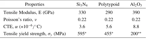
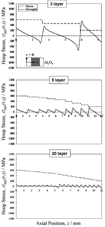
Figures 7 through 9 show the axial, radial, and hoop stress distributions of the 3, 9, and 20-layer FGMs. These data were obtained from the 3-D FEA results to show individual stress components.
For the axial stress atr¼Rin the 3-layer joint, the range of stress was found to be from 997 MPa to 967MPa whereas in the 20-layer FGM, the range of stress was found to
Fig. 7 Comparison of the computed axial stress,zzatr¼Ras a function of axial position,z, for the FGM.
[image:4.595.65.269.66.512.2] [image:4.595.323.525.70.514.2]be from 251 MPa to98MPa. The result showed a dramatic decrease in axial stresses as well as in the radial and hoop stresses as the number of FGM layers increases. Along with the stress components, calculated strengths were plotted with dotted lines in these figures. Since ceramic is generally weaker in tension than compression, only tensile strength was plotted for comparison with each stress component.
Although the individual comparison of stress values with strengths cannot exactly predict locations of cracks of the FGMs, among three stress components, radial stresses dominantly affect the failures of the samples. For 3-layer and 9-layer FGMs, Al2O3 side radial stresses reached about the same or higher stresses than strength values (Fig. 8). The information obtained from these individual stress analyses
FGM changes from three layers to 20 graded layers. Similar trends in stress reduction were observed in Von Mises failure criterion. The analysis using Von Mises criterion agreed better with experimental data than that by maximum stress criterion. Such analyses are especially useful for graded FGM samples where the residual stresses are very difficult to measure experimentally.
Acknowledgements
This work was supported by the Director, Office of Basic Energy Sciences, Division of Materials Sciences of the United States Department of Energy, Micro Thermal System Research Center of Seoul National University and the Korea Research Foundation Grant funded by the Korean govern-ment (MOEHRD, Basic Research Promotion Fund) (KRF-2006-311-D00516).
REFERENCES
1) K. Ravichandran: Mater. Sci. Eng. A.201(1995) 269–276. 2) D. Munz and Y. Y. Yang: J. Appl. Mech.59(1992) 856–861. 3) C. S. Lee, X. Zhang and G. Thomas: Acta Mater.49(2001) 3775–3780. 4) R. Watanabe, A. Kawakasi and H. Takahashi: Mechanics and Mechanisms of Damage in composites and Multi-Materials, (Mechan-ical Engineering publication, London, 1991) pp. 285–299.
5) M. Koizumi: Ceram. Eng. Sci. Proc. July-August (1992) 333–347. 6) B. H. Rabin and R. L. Williamson:Microcomposites and Nanophase
Materials, ed. by D. C. Van Aken, G. S. Was and A. K. Ghosh, (TMS-AIME, Warrendale, PA, 1991) pp. 103–113.
7) R. Watanabe and A. Kawasaki:Composite Materials, ed. by A. T. Di Benedetto, L. Nicolais and R. Watanabe, (Elsevier Science, 1992) pp. 197–208.
8) M. Koizumi and K. Urabe:Ceramics Today Tomorrow’s Ceramics, ed. by P. Vincenzini, (Elsevier Science, 1991) pp. 1939–1945.
9) B. H. Rabin, R. L. Williamson, R. J. Heaps and A. W. Erickson:Proc. 1st Int. Conf. Advanced Synthesis of Engineered Materials, (San Francisco, CA, 1992) pp. 175–180.
10) C. S. Lee, L. C. De Jonghe and G. Thomas: Acta Mater.49(2001) 3767–3773.
11) C. S. Lee, S. H. Ahn, L. C. De Jonghe and G. Thomas: Mat. Sci. Engi. A.434(2006) 160–165.
12) website,www.algor.com. 13) website,www.goodfellow.com.
14) M. Ashby and K. Johnson: Materials and Design, (Butterworth Heinemann, MA, 2002) pp. 103–105.
Fig. 9 Comparison of the computed hoop stress,atr¼Ras a function
[image:5.595.66.272.74.519.2]