Slip Deformation Analysis Based on Full Constraints Model
for
-Titanium Alloy at Low Temperature
*Motoaki Morita
1and Osamu Umezawa
21Graduate School of Mechanical Engineering and Materials Science, Yokohama National University, Yokohama 240-8501, Japan
2Department of Materials Science and Engineering, Yokohama National University, Yokohama 240-8501, Japan
The effects of restricted slip conditions on both the Taylor factor and plastic work rate under the condition of tensile yielding have been analyzed in-titanium alloys at low temperatures, using the full constraints model. The role of secondary slip systems, i.e., thehaibasal slip and hcþaipyramidal slip, was clarified, when thehaiprismatic slip was dominant. Although no influence of secondary slip conditions on the Taylor factor was detected, the plastic work rate was sensitive to the operating secondary slip systems. When the basal system was chosen as the secondary slip system, the plastic work rate increased in all tensile axes, especially aroundh0001i. In addition, no basal slip operation decreased the plastic strain energy. The plastic work rate was the highest along theh0001itensile axis, and the operation of thehcþaipyramidal slip was necessary to achieve plastic deformation alongcaxis. High elastic strain energy, therefore, must accumulate to a high level aroundh0001i, because the pyramidal slip is hardly active owing to its very high critical resolved shear stress. [doi:10.2320/matertrans.L-M2011815]
(Received February 14, 2011; Accepted April 30, 2011; Published July 25, 2011)
Keywords: Taylor factor, critical resolved shear stress, hexagonal close packed structure, fatigue, primary slip
1. Introduction
Subsurface crack generation in the high-cycle fatigue of
-titanium alloys is dominant at low stress regimes and
temperatures.1)The crack initiation sites appear at crystallo-graphic facets such as the (0001) transgranular cracking.2–5) The dislocation movement of the alloys is nearly planar and f01110gh11220i arrays pile up near grain boundaries.2)
The local stress concentration near a grain boundary due to heterogeneous slip may lower the high-cycle fatigue strength and cause the subsurface crack initiation. Therefore, it is necessary to consider crystal plasticity in the cyclic deformation and fatigue fracture mechanism. Here, the fatigue process is divided into four stages: (1) development of a saturated dislocation structure by cyclical micro-plastic strain accumulation, (2) generation of localized slip and/or microcracking to relax the stress concentration at the vicinity of a boundary, (3) microcrack growth and transition to main crack, and (4) crack propagation.3)In stages 3 and 4, linear mechanics can be applied to evaluate the critical size
of the subsurface crack (facet) for propagation6) and the
crack propagation life.7)However, stages 1 and 2, which are based on estimated models, do not exhibit direct evidence of cracking and macroscopic support. Thus, the evaluation based on crystal plasticity complements the construction of a sophisticated model of subsurface fatigue crack initiation.
In stage 1, the f01110gh11220i dominant slip operates in some grains; this slip depends on the crystal orientation. Moreover, both plastic and elastic deformations coexist in polycrystalline specimens. In stage 2, regardless of whether the origin of transgranular cracking is slip-off (slip local-ization) or microcracking on a crystal plane, the plastic deformation on the facet plane hardly yields and the elastic field normal to the facet plane has to accumulate. The activity
of slips, needed for any micro-yielding, can be evaluated on the basis of the full constraints model using Taylor analysis.8,9) Subsequently, the deformation behavior of the secondary slips in a locally yielded grain describes the elastic (stress) field in stages 1 and 2. The full constraints model is based on the assumption of homogeneous deformation in polycrystalline specimens and has been mainly applied to understand the homogeneous and large-scale deformation in face-centered cubic (f.c.c.) metals.8,9) Occasionally, the
full constraints model has been applied to slip analysis in hexagonal closed packed (h.c.p.) metals, because twinning has a great influence on their homogeneous and large-scale
deformation.10) In the present study, we adopted the full
constraints model in order to evaluate the critical resolved
shear stresses (CRSSs) in the primary slip system of
-titanium at low temperatures. In addition, we calculated the external (internal) plastic work rate and Taylor factor to discuss the effect of the primary slip system on slip behavior and that of the crystal orientation on the stress field.
2. Procedure
2.1 Application of full constraints model
A grain in the tensile stress field that develops by cyclic deformation is constrained by its neighbors in a polycrystal-line specimen. The full constraints model, in which all the grains in the field exhibit the same strain, was adopted to sustain the strain compatibility between neighboring grains. That is, to satisfy the full constraints, multiple slips were introduced in a grain. In the tension mode, the compatibility in a polycrystalline specimen can be achieved by operating
five independent slip systems.8,9) When an uniaxial tensile
strain is parallel to the z-axis in the specimen’s coordinate system, XYZ, grain deformation takes place under axial symmetry at a fixed volume (d"xxþd"yyþd"zz¼0):11)
d"xx ¼d"yy¼
1
2d"zz ð1Þ
dxy ¼dyz¼dzx¼0 ð2Þ
*This Paper was Originally Published in Japanese in J. JILM60(2010) 61–67. In Regard to the Paper, the Erratum was Published on Page 296, Vol. 61 of J. JILM.
whered"xx,d"yy andd"zzare the plastic strain rate, anddxy,
dyzanddzx are the plastic shear strain rate in a grain. The
internal plastic work rate dw is the increment of work per
volume and it is the sum of the work of five independent slip systems in a grain:
dw¼X
i
di¼ X
i
jdij ði¼1;2; ;5Þ ð3Þ
wherei is the CRSS anddiis the slip rate in thei-th slip system. There are a number of combinations of operating slip systems that satisfy the external work constraint, but only one combination is to be chosen. Each time ideal plastic deformation take places,dwequals the external plastic work rate as in eq. (4):
dw¼d¼zzd"zz ð4Þ The Taylor factorM is calculated using eq. (4) as
zz
¼
d
d"zz
¼M ð5Þ
M represents the total of the slip rates in five independent
slip systems for the strained grain, and depends on the
relationship between the tensile axis (z-axis) and grain
orientation.
2.2 Evolution of full constraints model applied to low-temperature slip deformation in-titanium
2.2.1 Coordinate transformation in hexagonal lattice The strain rate tensord"ijin the specimen space is equal to the strain rate tensorPkEk
ij, which is the sum of the strain rate tensors in five independent slip systems:
d"ij¼
d"xx dxy dxz
dyx d"yy dyz
dzx dzy d"zz 0
@
1
A¼X
k
Ekij ði;j¼1;2;3Þ ðk¼1;2; ;5Þ
ð6Þ
In the specimen coordinate system, theEk
ijare described by the slip direction vectorband the normal vector direction to
the slip plane n, where the coordinate transformation from
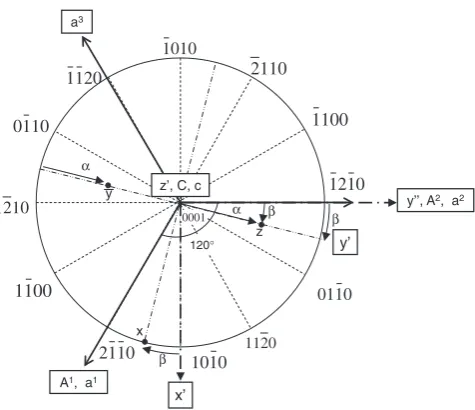
the Miller-Bravais index in the crystal to the orthogonal coordinate system in the specimen was done under the coordinates shown in Fig. 1. First,bmbi [i j k h] given by the Miller-Bravais index (axis:a1,a2,a3,c) was transformed into
bnorh [(i-k) (i-j) (c=a)h] in the nonorthogonal coordinate system (axis: A1, A2, C, ¼120), and then borh in the
orthogonal one (axis:x0,y00,z0) as
borh¼Qbnorh ð7Þ
Qis the coordinate transformation tensor which represents
the relationship between the unit vector of axes in the nonorthogonal coordinate systemðA1;A2;CÞand that in the
orthogonal one ðx0;y00;z0Þ. Second, the normal vector to the slip planenorhwas estimated from the exterior product of the
two slip directionsborh1 andborh2 on a slip plane as
norh¼borh
1 b
orh
2 ð8Þ
Subsequently, thenorhandborh
, represented in the orthogonal
coordinate system in the crystal, were transformed to then
andbin the orthogonal coordinate system in the specimen as eq. (9):
ðnior biÞ ¼
cos sin 0
cossin coscos sin
sinsin sincos cos
0 B @
1 C A
ðnorhi or borhi Þ
ði¼1;2;3Þ ð9Þ
where angular parameters and represent the
trans-formation from the orthogonal coordinates in the crystal to
those in the specimen, xyz, (Fig. 1). The rotation angle
(0< <90) along the x-axis in the orthogonal coordi-nates, xy0z0, gives the transform into the orthogonal coor-dinates,xyz. The angle(0< <90) alongz0-axis in the orthogonal coordinates, x0y00z0, gives the transform into the xy0z0.
2.2.2 Influence of critical resolved shear stress
Only the principal slip systems, i.e., f01110gh11220i, f0001gh11220i, and f10111gh11223i were taken into account
for the deformation mode in -titanium alloy.13–16) In
addition, no deformation twinning and "-martensite were considered. Because the CRSSs in the slip systems are different from each other, especially at low tempera-tures,10,12–14,16) eqs. (3) and (5) are modified to permit the
multiple slips as given by eqs. (10) and (11) under the full constraints model:
dw¼X
i
ijdij ði¼1;2; ;5Þ ð10Þ X
i jdij
d"zz
¼M ði¼1;2; ;5Þ ð11Þ
where M is the newly defined sum of the slip rates in the
operating slip systems within a grain per unit strain, because it cannot be directly found by the yield stress. In a randomly oriented polycrystal under uniaxial tension parallel to the z-axis, the deformation is denoted as
A1, a1
y’’, A2, a2
z’, C, c
1010 2110
1100
0110
1210
1100 1210
1120 2110
1010
1120
0110
0001 β
a3
x’ 120°
α α
x y
z β
y’
β
Fig. 1 Definition ofandon the standard stereographic projection of (0001) plane with Miller-Bravais indexða1;a2;a3;cÞ, orthogonal coor-dinates system ðx0;y00;z0Þ, and nonorthogonal coordinates system
[image:2.595.309.547.69.274.2]X
i
ijdij ¼zzd"zz ði¼1;2; ;5Þ ð12Þ
To evaluate the effect of the CRSSs in the principal slip
systems onM anddw, six types of models were examined
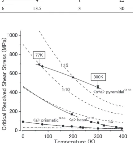
(Table 1). In Type 1, the CRSSs of the three active slip systems are the same. In Types 2–6,f01110gh11220iis fixed as the primary slip system. Types 2–4 simply represent the act of choosing the secondary slip system from f0001gh11220i andf10111gh11223i. Each CRSS of the secondary slip systems is from five to fifteen times as high as that off01110gh11220iin the low-temperature regime (Fig. 2). Subsequently, it was assumed that the CRSS of the secondary slip systems was ten times that of the primary or more. What the active of two secondary slip systems was distinguished, the ratio of either system was chosen as fifteen. In Types 5 and 6, the ratio of the CRSSs in the three systems was given by the estimated values at 300 and 77 K, respectively. The CRSSs of f10111gh11223i and f01110gh11220i were derived from the experimental data for single crystal-titanium,12,15)although
it is hard to evaluate the CRSSs of f0001gh11220i and
f10111gh11223i at low temperatures due to deformation
twinning.14) Then the CRSS of f0001gh11220i below 200 K
was estimated by thebasalð¼þ0Þ, where the thermal
and athermal component 0 were given by the thermal
activated process. The CRSS off10111gh11223iwas also given by the data of Ti-6 mol%Al.12)
3. Results
3.1 Influence of slip systems on Taylor factor
When the CRSSs of the active slip systems are equivalent
(Type 1), Mmax is 2.792 at the tensile axis with ð; Þ ¼
ð57;30ÞandMmin is 2.075 withð; Þ ¼ ð19;8Þas shown in
Fig. 3. The M value is 2:4732:792 in the region of
¼4560 and there is no big difference between M
max
and Mmin. Thus, the factor M is almost isotropic in any
crystallographic orientation in Type 1.
When the primary slip system is given as f01110gh11220i
and regardless of Types 2–4, no difference of M and its
dependence on the tensile axis is present (Fig. 4). Mmax is
3.282 at the tensile axis with ð; Þ ¼ ð33;30Þ and Mmin is
2.075 withð; Þ ¼ ð19;8Þ. In the tensile axes with <19 and >82, theirMfactors are the same as that in Type 1.
In Types 2–4, however, the M factor is remarkably higher
than that in Type 1 around the tensile axes with ð; Þ ¼
ð19;8Þandð; Þ ¼ ð70;0Þ. A high gradient inM, therefore,
is produced at or near¼19 and¼82.
[image:3.595.307.547.71.220.2]In the simple analysis by the Sachs model where only the primary slip system operated, theMfactor was 6.5.17)When
Table 1 Ratios in critical resolved shear stresses of major slip systems. (reference:f01110gh11220iat 300 K)
Type Ratio of CRSS
f0001gh11220i f01110gh11220i f10111gh11223i
1 1 1 1
2 10 1 10
3 10 1 15
4 15 1 10
5 4 1 22
6 13.5 3 30
77K
300K
12, 13)
12-15) 12-14)
Fig. 2 Relationship between critical resolved shear stress (CRSS) and temperature forhaiprismatic,haibasal, andhcþaipyramidal slips in -Ti. Dashed curved lines indicate scales with 5, 10, and 15 times as large as the CRSS of hai prismatic slip. The dashed-dotted line indicates the athermal component ofhaibasal slip in pure Ti.15)
[1210]
[0001]
Mmax= 2.792 ;(α, β)=(57, 30)
Mmin= 2.075 ;(α, β)=(19, 8)
2.468 2.389
[0110] 2.389
0 10 20 30 40 50 60 70 80 90
α(degree)
0 10 20 30
Fig. 3 Dependence of Taylor factor on tensile axis under the condition of homogeneous primary slips.
Mmax= 3.282 ; (α, β)=(33, 30)
Mmin= 2.075 ;(α, β)=(19, 8)
[0001]
2.468
[1210] 2.389 [0110] 2.389
0 10 20 30
0 10 20 30 40 50 60 70 80 90
α(degree)
[image:3.595.60.277.185.419.2] [image:3.595.309.549.278.421.2]the homogeneous slip deformation is ideally available in a grain as in this study, the averageM,Mave, is about half theM
factor of the Sachs model on all tensile axes and types (Type 1:Mave¼2:42, Types 24:Mave¼2:63, Types 56:
Mave¼2:46).
3.2 Influence of secondary slip systems on plastic work rate
When f01110gh11220i was chosen as the primary slip
system,dwhighly depended on the operating secondary slip
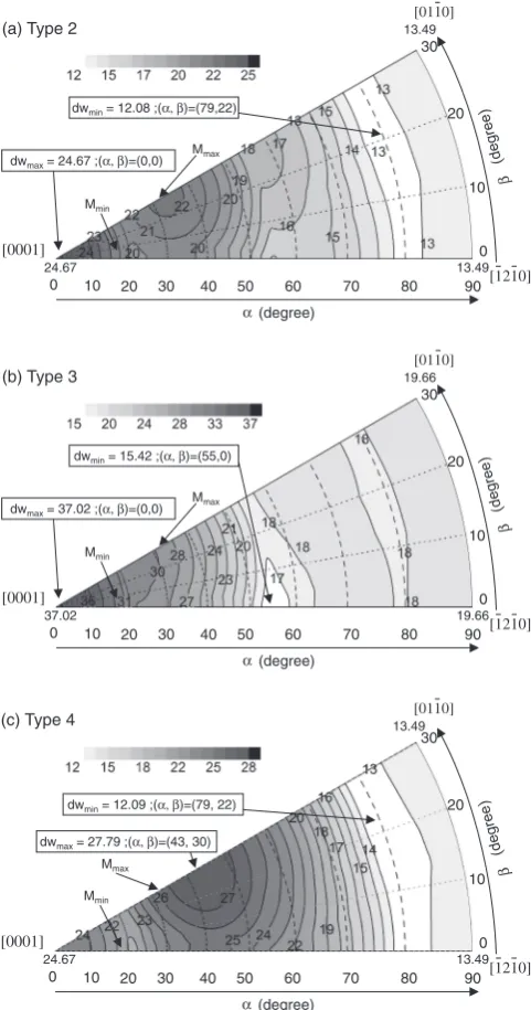
systems. Whenf0001gh11220iandf10111gh11223iwere opera-tionally equivalent to secondary slip systems (Type 2), the tensile axes of the plastic work rate maximum,dwmaxand the
minimum,dwminwere different with those ofMminandMmax,
respectively (Fig. 5(a)): thedwmaxis 24.67 atð; Þ ¼ ð0;0Þ,
and thedwmin is 12.08 atð; Þ ¼ ð79;22Þ.dwcontinuously
decreases asincreases from 0to 80.
When f0001gh11220i was chosen as the secondary slip
system and the operation of f10111gh11223i was prevented
(Type 3), dw was higher than that of Type 2 in all of the
tensile axes (Fig. 5(b)).dwmaxis 37.02 at the same axis with
ð; Þ ¼ ð0;0Þas in Type 2, and dwmin is 15.42 at ð; Þ ¼
ð55;0Þ. The tensile axes of dwmax and dwmin are also not
consistent with those ofMminandMmax.dwmaxis 1.5 times as
high as that in Type 2 anddwis 1.3 times at¼2070. At
around¼55,dwis almost the same with that in Type 2,
therefore, the restriction of thef10111gh11223ioperation is not responsible for the plastic work rate.
When f10111gh11223i was chosen as the secondary slip system and the operation of f0001gh11220i was prevented
(Type 4),dwincreased in the region of¼2070 where
the axis withð; Þ ¼ ð43;30Þgavedwmax 1.3 times as high
as that in Type 2 (Fig. 5(c)). Near the axes of ¼0 and
¼90, dw is almost the same with dw
min and that in
Type 2.
3.3 Slip deformation behavior of -titanium alloys at low temperature
The dependence of the tensile axis direction onM anddw
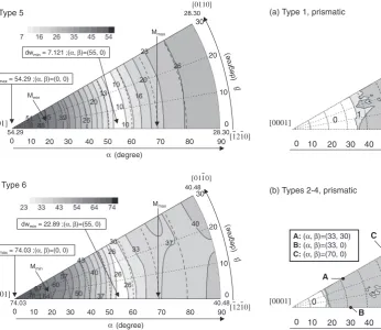
was evaluated at 300 K. The 300 K CRSS of each slip system was adopted, as listed in Table 1 (Type 5).Mmax is equal to
2.882 at ð; Þ ¼ ð70;0Þ, as shown in Fig. 6, and dwmax is
equal to 54.92 atð; Þ ¼ ð0;0Þ.dwcontinuously increases as the angle increases and equals 7.12 at ð; Þ ¼ ð55;0Þ. At
77 K (Type 6),M is the same as that of Type 5 (Fig. 7(b)).
Both dwmax (74.03) and dwmin (22.89) also have the same
tensile axes as those in Type 5. Type 3 gave a similar ratio of CRSS with Types 5 and 6. The results at 300 K and 77 K
show almost the same dependence ofdwon tensile axis with
Type 3, although their tensile axis ofMmaxis different from
that of Type 3.
4. Discussion
4.1 Dependence of dominant slip system on tensile
axis
TheMfactor around the tensile axes withð; Þ ¼ ð33;30Þ and ð; Þ ¼ ð70;0Þ is higher in Types 2–4, where f01110gh11220i is the primary slip system (Fig. 4), than that in Type 1 where the CRSSs of three primary slip systems are dwmax= 24.67 ;(α, β)=(0,0)
dwmin= 12.08 ;(α, β)=(79,22)
[0001]
24.67
13.49
13.49 Mmax
Mmin
0 10 20 30
0 10 20 30 40 50 60 70 80 90
α(degree)
[1210] [0110]
(a) Type 2
dwmax= 37.02 ;(α, β)=(0,0) dwmin= 15.42 ;(α, β)=(55,0)
[0001]
37.02
19.66
19.66 Mmax
Mmin
0 10 20 30
0 10 20 30 40 50 60 70 80 90
α(degree)
[1210] [0110]
(b) Type 3
dwmax= 27.79 ;(α, β)=(43, 30) dwmin= 12.09 ;(α, β)=(79, 22)
[0001]
24.67
13.49
13.49 Mmax
Mmin
0 10 20 30
0 10 20 30 40 50 60 70 80 90
α(degree)
[1210] [0110]
(c) Type 4
Fig. 5 Dependence of plastic work rate on tensile axis direction under the conditions of Types 2, 3, and 4.
Mmax= 2.882 ;(α, β)=(70, 0)
Mmin= 2.075 ;(α, β)=(19, 8)
[0001]
2.468
2.389
2.389 0 10 20 30
0 10 20 30 40 50 60 70 80 90
α(degree)
[1210] [0110]
[image:4.595.48.289.73.531.2] [image:4.595.305.550.73.216.2]the same (Fig. 3). It is suggested that the region of the tensile axis operating atf01110gh11220ishould be enlarged to increase its slip rates. In this section, the relationship between the operating slip system and slip rate is discussed.
The number of active slips off01110gh11220iin Types 2–4
is increased from 0 to 2 at the tensile axis around¼33
relative to Type 1 (Fig. 8). Because f01110gh11220i has two independent slips, it seems to dominate the deformation
around ¼33 in the tensile axis. However, the increase
of M depends on the angles as well (Fig. 4), and in that
case the number of active slips in the primary system is not sufficient to discuss the dominant slip system during deformation. Here, the tensile axes, -indicated as points of A: ð; Þ ¼ ð33;30Þ, B:ð; Þ ¼ ð33;0Þ, and C: ð; Þ ¼ ð70;0Þ in Fig. 8(b) were chosen to represent the axes that
increasedM in Types 2–4. All five active slip systems and
their slip rates in Types 2–4 were evaluated (Table 2).
Point A gives the axis ofMmaxin Types 2–4.Mmax shows
an increase of 0.941 relative toMat the same axis in Type 1. There are two sets of five independent slip systems for minimum work at the axis listed in Table 2 as A-1 and A-2.
Each set involves two kinds of f01110gh11220i, i.e.,
ð11100Þ½11220andð10110Þ½112110, and either ð11100Þ½11220or ð10110Þ½112110, revealing a large slip rate. However, their Schmid factors are the same and as low asS¼0:12816,18)so
that the f01110gh11220i is geometrically hard to operate. In Types 2–4, therefore, the restrictions of other slip systems result in the operation of f01110gh11220i because of their higher CRSSs. The operation of f01110gh11220i in tension along axis A should be accompanied by deformation along thec-axis. As a result, the slip rate off10111gh11223imay be high.
At tensile axis B, the Schmid factors of the two slip systems, ð11100Þ½11220 and ð01110Þ½22110 are the same dwmax= 54.29 ;(α, β)=(0, 0)
dwmin= 7.121 ;(α, β)=(55, 0)
[0001]
54.29
28.30
28.30 Mmax
Mmin
0 10 20 30
0 10 20 30 40 50 60 70 80 90
α(degree)
[1210] [0110]
(a) Type 5
dwmax= 74.03 ;(α, β)=(0, 0) dwmin= 22.89 ;(α, β)=(55, 0)
[0001] 74.03
40.48
40.48 Mmax
Mmin
0 10 20 30
0 10 20 30 40 50 60 70 80 90
α(degree)
[1210] [0110]
(b) Type 6
Fig. 7 Dependence of plastic work rate on tensile axis under the conditions of Types 5 (a) and 6 (b).
[0001]
0 10 20 30 40 50 60 70 80 90
α(degree)
0 10 20 30
[1210] [0110] (a) Type 1, prismatic
1
2
0 1
[0001]
0 10 20 30 40 50 60 70 80 90
α(degree)
0 10 20 30
[1210] [0110]
A
B C A: (α, β)=(33, 30) B: (α, β)=(33, 0) C: (α, β)=(70, 0) (b) Types 2-4, prismatic
1
2
0
[image:5.595.245.539.68.391.2]Fig. 8 Number of active prismatic slip systems under the conditions of Type 1 (a) and Types 2, 3, and 4 (b).
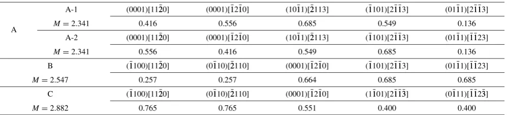
Table 2 Active five independent slip systems and their slip rates for tensile directions A, B, and C shown in Fig. 8(b).
A-1 ð11100Þ½11220 ð10110Þ½112110 ð0001Þ½11220 ð0001Þ½112110 ð01111Þ½211113
A M¼3:282 0.898 0.257 0.204 0.553 1.370
A-2 ð11100Þ½11220 ð10110Þ½112110 ð0001Þ½11220 ð0001Þ½112110 ð01111Þ½111123
M¼3:282 0.257 0.898 0.553 0.204 1.370
B ð11100Þ½11220 ð01110Þ½22110 ð0001Þ½112110 ð11101Þ½211113 ð01111Þ½111123
M¼2:547 0.257 0.257 0.664 0.685 0.685
C ð11100Þ½11220 ð01110Þ½22110 ð0001Þ½112110 ð11101Þ½2111133 ð01111Þ½1111233
[image:5.595.61.408.74.374.2] [image:5.595.52.552.446.559.2](S¼0:128) and equal to the ones at axis A. Furthermore, their slip rates are small. Thus, f01110gh11120i is less conducive to deformation in total even though it becomes active.
At the tensile axis C, bothð11100Þ½11220andð01110Þ½22110 can easily operate, because their Schmid factors are high (S¼0:382) andf01110gh11220ioperates more easily when the secondary slip systems are suppressed.
In Types 5 and 6, the slip systems and their slip rates were also evaluated (Fig. 9 and Table 3). Because every active slip system and its slip rates in Types 5 and 6 are the same as those in Types 2–4 at the tensile axes B and C, the deformation behavior off01110gh11220i in Types 5 and 6 is similar to those in Types 2–4. At the tensile axis A, however, Mis not higher than that in Type 1. Nof01110gh11220isystem is chosen, but three systems in f10111gh11223i are active (Table 2). Therefore, f0001gh11220i and f10111gh11223i are dominant at the tensile axis A.
Based on the above, the dominant deformation mode of f01110gh11220i and the role of the secondary slip systems in the homogeneous deformation is discussed in sections 4.2 and 4.3.
4.2 Dominant deformation modes in primary slip sys-tems
When all the CRSSs of the primary slip systems are the same (Type 1), f01110gh11220i can hardly operate at the
tensile axes around A and C whereM shows a steep incline.
When the operation off01110gh11220iis predominant (Types
2–4), bothf0001gh11220iandf10111gh11223iare hardly active. Then, f01110gh11220i must operate (Fig. 8(b)), and its slip rates has to increase. Therefore, f01110gh11220i is the dominant mode. The same mode appeared in Types 5 and
6, but the secondary systems of f0001gh11220i and
f10111gh11223i are also dominant at the tensile axis A. At the tensile axis B in Types 2–6, the two slip systems of f01110gh11220iare chosen (Figs. 8(b) and 9(a)) but also their slip rates are small (Tables 2 and 3). Therefore, it is not f01110gh11220i, but f0001gh11220i andf10111gh11223i that are the dominant modes at the B axis.
The tensile axis where the primary slip system
f01110gh11220i is dominant is evaluated. In Types 2–4, the steep incline ofMat the tensile axes around¼18and 77 (Fig. 4) must originate in the extension of the region where f01110gh11220iis dominant.
The increase ofMfrom the condition of Type 1 is smaller
at the tensile axes with ¼4077, although the Schmid
factor is higher.16,18)In this regime,Mis comparatively high
regardless of the secondary slip systems’ operation, and the number of activef01110gh11220iis mostly the same (Fig. 8). dwis also not so sensitive on the restrictions of the secondary
slip systems (Fig. 5). At a tensile axis with ¼4077,
the secondary slip systems have less of an effect on the deformation, therefore,f01110gh11220iis dominant.
Hence, the primary slip system f01110gh11220i is the dominant mode at the tensile axes around A, C and for
¼4077, when the operation of the secondary slip
systems is suppressed (Types 26).
[0001]
0 10 20 30 40 50 60 70 80 90
α(degree)
0 10 20 30
[1210] [0110] (a) Types 5 and 6, prismatic
0
1
1 2
A
B C
[0001]
0 10 20 30 40 50 60 70 80 90
α(degree)
0 10 20 30
[1210] [0110] (b) Types 5 and 6, pyramidal
1
5
4
2
3 3
4 A
B C A: (α, β)=(33, 30) B: (α, β)=(33, 0) C: (α, β)=(70, 0)
[image:6.595.53.548.75.226.2]Fig. 9 Number of active slip systems under the conditions of Types 5 and 6 for prismatic (a) and pyramidal (b).
Table 3 Active five independent slip systems and their slip rates for tensile directions A, B, and C shown in Fig. 9.
A-1 ð0001Þ½11220 ð0001Þ½112110 ð10111Þ½22113 ð11101Þ½211113 ð01111Þ½211113
A M¼2:341 0.416 0.556 0.685 0.549 0.136
A-2 ð0001Þ½11220 ð0001Þ½112110 ð10111Þ½22113 ð11101Þ½211113 ð01111Þ½111123
M¼2:341 0.556 0.416 0.549 0.685 0.136
B ð11100Þ½11220 ð01110Þ½22110 ð0001Þ½112110 ð11101Þ½211113 ð01111Þ½111123
M¼2:547 0.257 0.257 0.664 0.685 0.685
C ð11100Þ½11220 ð01110Þ½22110 ð0001Þ½112110 ð11101Þ½2111133 ð01111Þ½1111233
[image:6.595.52.551.290.403.2]4.3 Role of secondary slip systems in homogeneous deformation
The tensile deformation in which f01110gh11220i is pre-dominant is discussed. In Type 3 where the f10111gh11223i operation is suppressed (Fig. 5(b)),dwis higher than that in Type 2 at all tensile axes (Fig. 5(a)). Because the operations of f0001gh11220i and f10111gh11223i are equivalent as the secondary slip system in Type 2, the deformation in arbitrary shape needs an operating system of f10111gh11223i at least (Fig. 10(a)). Furthermore, f10111gh11223i is the dominant
mode at the tensile axis at ¼030, because dw is
remarkably higher there. Especially at the [0001] tensile axis, Mis relatively lower than the rest (Fig. 4), and the operating five slips are covered with only the f10111gh11223i system at the tensile axis at¼020(Fig. 10(a)). Thus, an operation of f10111gh11223i is necessary to deform homogeneously at the tensile axis around [0001]. However, it is difficult to observef10011gh11223idislocations in tension along [0001] at low temperature.10) Because the CRSS of f10011gh11223i is
increased at lower temperature,10,12) dw is higher at the
tensile axis of [0001] (Fig. 7(b)).
In the tensile axes at¼7790,dwis not sensitive to the activity off10111gh11223ias shown in Fig. 5, although a few f10111gh11223i systems are operative there (Fig. 10(a)). Namely, the f10111gh11223i slip system is not dominant in
the tensile axes at ¼7790. In the tensile axes at ¼
4565, other slip systems are dominant, because the activity off10111gh11223iis not responsible fordw(Fig. 5).
The slip systems of f01110gh11220i andf0001gh11220i are
mainly chosen in the tensile axes at¼4560 (Fig. 10).
When the operation off0001gh11220iis suppressed (Type 4), dwin the tensile axes at¼3065 is higher than that in Type 2 where the secondary slip systems of f0001gh11220i andf10111gh11223iare operative (Fig. 5).dwmaxis also given
at the tensile axis with ð; Þ ¼ ð43;30Þ in Type 4. Con-sequently, the f0001gh11220i operation is dominant in the tensile axes at¼3065, but it is not active in all tensile axes (Fig. 10(b)). Thus, thef0001gh11220ioperation results in loweringdwand is not necessary for arbitrary deformation.
In tensile axes at¼7790, the secondary slip systems are not dominant. The primary slip systemf01110gh11220ithat is dominant agrees with the high Schmid factor.17,18)
Figure 11 shows the dominant slip systems for arbitrary deformation, whenf01110gh11220iis the primary slip system. When the operation of the secondary slip systems is suppressed, plastic deformation hardly proceeded in the tensile axes at¼040.
4.4 Slip deformation in low-temperature high-cycle fatigue of-titanium alloy
According to the analysis using the CRSSs of-titanium
alloys at 77 and 300 K (Types 5 and 6), the operation of f01110gh11220i and f0001gh11220i is preferred in the tensile
axes at¼4065, as shown in Fig. 10 wheredwis low.
However, the operation needs a large slip rate to produce unit strain in a grain, because theirMvalues are high. The slip rate may result from the increasing dislocation density so that the piled-up dislocations onf01110gh11220iandf0001gh11220i should readily occur. The analysis agrees with the exper-imental result in which piled-up dislocations off01110gh11220i were observed in the fatigued samples at 77 K.2)
The operation off10111gh11223iis dominant at tensile axis with ð; Þ ¼ ð0;0Þ where dwmax is given. However, the
operation off10111gh11223iis hard, because its CRSS is high at low temperature. In fact, the operation off10111gh11223iin the fatigued samples can be hardly observed by transmission electron microscopy.2)Therefore, a large elastic strain field may accumulate under this condition. Facet or facets of {0001} were detected in the subsurface fatigue crack
initiation site of -titanium alloys.1–5) It supports the
development of opening stress (mode I) normal to {0001}. It is difficult to understand the transgranular cracking on [0001]
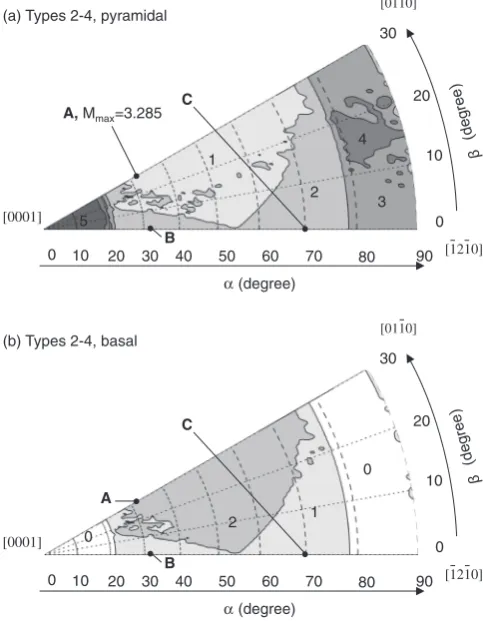
0 10 20 30 40 50 60 70 80 90
α(degree)
0 10 20 30
[1210] [0110]
A, Mmax=3.285
B C (a) Types 2-4, pyramidal
1
5
4
2 3
[0001]
0 10 20 30 40 50 60 70 80 90
α(degree)
0 10 20 30
[1210] [0110] (b) Types 2-4, basal
1 2
0
0
A
[image:7.595.311.542.69.210.2]B C
Fig. 10 Number of active slip systems under the conditions of Types 2, 3, and 4 for pyramidal (a) and basal (b).
[0110]
[1210]
[0001]0 10 20 30 40 50 60 70 80 90
α(degree)
0 10 20 30
prismatic + basal
prismatic prismatic + pyramidal (Types 2-4)
or
basal + pyramidal (Types 5-6)
pyramidal
basal + pyramidal
[image:7.595.47.289.77.388.2]{0001} due to the opening stress only. A few models of cracking mechanism have been proposed. One is trans-granular cracking on {0001} due to the combination of internal stress concentration and applied stress.19)The other
is the slip-off on {0001} and its growth due to localized slip
deformation.2) There is a strong possibility that slip-off
occurs, because the development of dislocation pile-ups on {0001} is preferred. However, no direct evidence of the cracking has been found.
In high-cycle fatigue fracture of -titanium alloys, the
facet of f01110g20) or f11222g21,22) has been also detected at the crack initiation site. It was pointed out that there was a
possibility to form the f01110g facet due to the stress
concentration with dislocation pile-ups of f01110gh11220i andf0001gh11220ias well as the {0001} facet. Elastic stress
can be accumulated normal to f10110g at low temperature,
because dw is comparatively high at the tensile axis at
¼90, as shown in Fig. 7. The cracking off11222gtwin is different from that of {0001} andf01110gcracking, and may occur by another mechanism. An advanced deformation model that also considers twinning needs to be developed.
5. Conclusions
We evaluated the role of primary slip systems in tensile yielding and stress accumulation in-titanium alloys at low temperatures by using the Taylor model. The major con-clusions are as follows:
(1) The primary slip systemf01110gh11220iwas dominant in the tensile axes nearð; Þ ¼ ð33;30Þand¼4090. (2) The operation of f0001gh11220i decreased the plastic
work rate in the tensile axes at ¼3065 and was
responsible for arbitrary deformation.
(3) The secondary slip systemf10111gh11223iwas dominant
in the tensile axes at ¼030. The operation of
f10111gh11223iwas related to the deformation in all ten-sile axes and was necessary for arbitrary deformation.
(4) The plastic work rate was high at ð; Þ ¼ ð0;0Þ,
because CRSS of f10111gh11223i was high at low
temperatures.
(5) The dislocation pile-ups of f0001gh11220i and
f01110gh11220imay be the largest in the tensile axes at
¼4065.
(6) The highest elastic stress may be developed in the tensile axis atð; Þ ¼ ð0;0Þand may be responsible for (0001) transgranular cracking.
REFERENCES
1) O. Umezawa and K. Nagai: ISIJ Int.37(1997) 1170–1179.
2) H. Yokoyama, O. Umezawa, K. Nagai, T. Suzuki and K. Kokubo: Metall. Mater. Trans. A31A(2000) 2793–2805.
3) M. R. Bache, W. J. Evans and H. M. Davies: J. Mater. Sci.32(1997) 3435–3442.
4) C. Sarrazin, R. Chiron, S. Lesterlin and J. Petit: Fatigue Fracture Eng. Mater. Struct.17(1994) 1383–1389.
5) V. Sinha, M. J. Mills and J. C. Williams: Metall. Mater. Trans. A37A (2006) 2015–2026.
6) O. Umezawa, K. Nagai and K. Ishikawa: Tetsu-to-Hagane76(1990) 924–931.
7) M. Hamada and O. Umezawa: ISIJ Int.49(2009) 124–131. 8) W. F. Hosford: The Mechanics of Crystals and Textured Polycrystals,
(Oxford Univ. Press, 1993) pp. 56–85.
9) G. Y. Chin and W. L. Mammel: Trans. Met. Soc. AIME239(1967) 1400–1405.
10) S. Hanada: Tetsu-to-Hagane4(1990) 495–502.
11) Notation for differentiation can express as both Leibniz’s notation (dw,
d", andd) and Newton’s notation (WW_,""_, and_). Leibniz’s notation (dw,d", andd) is used in this paper.
12) H. Numakura: Materia Japan37(1998) 117–124.
13) H. Conrad, M. Doner and B. Meester: Titanium Science and Technology, Vol. 2, (Plenum, New York, 1973) pp. 969–1005. 14) N. E. Paton and W. A. Backofen: Metall. Trans.1(1970) 2839–2847. 15) E. D. Levine: Trans. Met. Soc. AIME236(1966) 1558–1564. 16) F. Bridier, P. Villechaise and J. Mendez: Acta Mater.53(2005) 555–
567.
17) R. Armstrong, I. Codd, R. M. Douthwaite and N. J. Petch: Phil. Mag.7 (1962) 45–58.
18) F. Bridier, P. Villechaise and J. Mendez: Acta Meter.56(2008) 3951– 3962.
19) M. R. Bache: Int. J. Fatigue25(2003) 1079–1087.
20) E. E. Sackett, L. Germain and M. R. Bache: Int. J. Fatigue29(2007) 2015–2021.
21) C. J. Beevers and M. D. Halliday: Metall. Sci.3(1969) 74–79. 22) Y. Ono, M. Demura, T. Yuri, T. Ogata, S. Matsuoka and S. Hori: Trans.