Influence of Heating Temperature on Interface Separation Behavior
between Ti-20 mol% Al Alloy and High Carbon Steel
Yasuhiro Morizono
1, Yoshikazu Kodama
1;*, Takateru Yamamuro
2and Minoru Nishida
31
Department of Materials Science and Engineering, Graduate School of Science and Technology, Kumamoto University, Kumamoto 860-8555, Japan
2Technical Division, Faculty of Engineering, Kumamoto University, Kumamoto 860-8555, Japan
3Department of Applied Science for Electronics and Materials, Interdisciplinary Graduate School of Engineering Sciences,
Kyushu University, Kasuga 816-8580, Japan
Ti-20 mol% Al (Ti-12.3 mass% Al) alloy was diffusion-bonded to high carbon steel (0.82 mass% C) at 1273 K for 3.6 ks in a vacuum. The joint had a space of a few micrometers in thickness between the Ti-20 mol% Al alloy and the steel, and several specimens separated near the interface promptly after the bonding treatment. This phenomenon is referred to as ‘interface separation’. This paper describes the influence of heating temperature on the interface separation. Diffusion bonding of the Ti-20 mol% Al alloy to the high carbon steel was carried out at 1173 to 1423 K for 0.9 to 3.6 ks in a vacuum, and then several joints were heated at a given temperature for up to 176.4 ks in an evacuated silica tube. At 1173 K, the separation phenomenon could not be confirmed even after prolonged heat treatment. This joint had four kinds of reaction regions in the vicinity of the interface, and their thicknesses increased in proportion to square root of holding time. On the other hand, the joint bonded at more than 1273 K showed the separation at the interface. As the heating temperature increased, the holding time required to induce the phenomenon became shorter. To clarify a time when the separation occurs in the diffusion bonding process, the joint with a special shape was prepared and quenched into the water from 1273 K. The generation of voids was recognized at the interface. These results suggest that the occurrence of the interface separation is associated with interdiffusion between the Ti-20 mol% Al alloy and the steel.
[doi:10.2320/matertrans.M2009035]
(Received January 30, 2009; Accepted May 7, 2009; Published July 1, 2009)
Keywords: Ti-20 mol%Al alloy, high carbon steel, diffusion bonding, interface separation, void
1. Introduction
Titanium aluminides, which are typified by Ti3Al and
TiAl, are usable as high temperature structural materials in the aerospace and automobile industries, because they have a low density and a high strength at elevated temperatures. They have been joined to themselves and other materials by various bonding methods to encourage their effective utilization. The authors have previously investigated the interfacial microstructures and the bonding strength of Ti-Al alloy/steel joints,1–3)since the steel is a dominant structural material in industrial products. In these studies, Ti-20 mol% Al (Ti-20Al, i.e. Ti-12.3 mass% Al) alloy was diffusion-bonded to high carbon steel (0.82 mass% C) at 1273 K for 3.6 ks in a vacuum. Although the obtained joint deceptively retained a bonding state, there was a space between the Ti-20Al alloy and the steel. Several specimens also separated near the interface promptly after the bonding treatment. We refer to this phenomenon as ‘‘interface separation’’. This is found to depend on alloy composition, carbon content in the used iron materials and bonding (heating) condition. Consequently, the Ti-20Al/high carbon steel joint bonded at 1073 K for 3.6 ks had a bonding strength of 166 MPa.2)
It is considered that the interface separation is attributed to preferential diffusion of Fe into the Ti-20Al alloy, which transforms from a Ti () + Ti3Al (2) duplex structure to an
single phase structure at about 1273 K.2,3)To evidence this proposition, we have to clarify a time when the separation occurs in the bonding treatment. If the Ti-20Al alloy removes from the steel on a cooling step from the heating temperature,
the influence of thermal stress and reaction products is considered as a cause of the separation. Meanwhile, if the destruction arises at the interface in a holding step at the heating temperature, interdiffusion across the interface is a dominant factor for the separation phenomenon.
In the present study, diffusion bonding of the Ti-20Al alloy to the high carbon steel was carried out at a wider temper-ature range of 1173 to 1423 K. If the separation occurs in the holding step in the bonding treatment, it is expected that the growth of reaction regions in the obtained joint has no connection with the heating temperature due to the inhibition of the diffusion of constituent elements. In addition, the joint with a special shape was prepared to quench into the water from the high-temperature region, and its microstructural aspect was investigated.
2. Experimental Procedure
Ti-Al binary alloy containing 20 mol% Al (12.3 mass% Al) was produced by using an arc melting process. The obtained ingot was homogenized at 1273 K for 86.4 ks in a vacuum of less than 3 mPa. Commercially produced carbon steel, which contained 0.82 mass% C, 0.18 mass% Si, 0.40 mass% Mn, 0.013 mass% P, 0.021 mass% S, 0.10 mass% Cr and 0.08 mass% Cu, specified as SK5 tool steel by the Japan Industrial Standards, was used as a mating material for the Ti-20Al alloy. The Ti-20Al alloy and the steel were machined into a rectangular block with dimensions of
5mm5mm3mm. The Ti-20Al alloy plate with a thickness of 0.3 mm was also prepared. These bonding surfaces were finished with #1200 emery paper. Before bonding treatment, the specimens were degreased in acetone using an ultrasonic cleaner and dried with hot air.
*Graduate Student, Kumamoto University. Present address: Kyocera
The Ti-20Al alloy was stacked on the steel as shown in Fig. 1(a). This couple was fixed in a jig consisting of two molybdenum rods and two austenitic stainless steel blocks, and heated in the range from 1173 to 1423 K for 0.9 to 3.6 ks in a vacuum of less than 3 mPa. The heating rate up to these temperatures was 0.17 K/s. Subsequently, several couples were heated at a given temperature for up to 176.4 ks in an evacuated silica tube. All specimens were cooled in the furnace to room temperature after a holding step in these treatments.
To investigate microstructural aspects at elevated temper-atures, the specimen for water-quenching was also fabricated. Its configuration is presented in Fig. 1(b). The Ti-20Al alloy plate was inserted between two steel blocks, and this couple was heated at 1173 K for 0.9 ks in a vacuum. The obtained joint was carefully machined into a columnar shape of 4 mm in diameter and 5 mm in height, and then packaged within a copper pipe. A space between the joint and the pipe was filled up with high carbon steel powder. It is expected that the introduction of cracks at the interface due to water-quenching can be avoided by coating the joint with the sintered steel
3. Results and Discussion
3.1 Interfacial microstructures at 1173 K
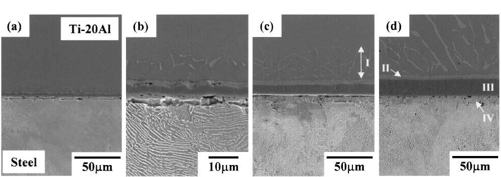
Figures 2(a) and 2(b) show SEM micrographs of the interface in the Ti-20Al alloy/high carbon steel joint bonded at 1173 K for 3.6 ks. Several reaction products were observed in the vicinity of the interface. This joint was also heat-treated at 1173 K for up to 176.4 ks, and the interfacial microstructures were shown in Figs. 2(c) and 2(d). In these figures, total holding time of the bonding and heat treat-ments is 90 and 180 ks, respectively. Four reaction regions indicated as I to IV were confirmed around the interface. To identify the reaction products and layers in regions I to IV, their composition ratios of Ti, Al and Fe were measured by using SEM-EDX. Table 1 shows the results of the compo-sition analysis. Region I was located in the Ti-20Al alloy and had needle-shaped products. From the results in Fig. 1 Configurations of bonding couples. (a) Normal specimen. (b)
Specimen for quenching from 1273 K.
Fig. 2 SEM micrographs of the interface in Ti-20Al alloy/high carbon steel joint bonded at 1173 K for 3.6 ks. (a) and (b) As-bonded. (b) After heat treatment at 1173 K for 86.4 ks. (c) After heat treatment at 1173 K for 176.4 ks.
Table 1 Chemical compositions of reaction products in regions I to IV shown in Fig. 2.
Analytical compositon (mol%) Resion
Ti Al Fe
I 78.7 8.3 13.0
II 66.4 29.1 4.5
III 98.6 0.2 1.2
[image:2.595.48.547.581.758.2]Table 1, the products are considered to be formed by the diffusion of Fe into the Ti-20Al alloy. Fe was also detected in the reaction layer indicated by II, and its content was lower than that in the needle-shape products in region I. Region III had a continuous layer along the interface between the Ti-20Al alloy and the steel. Since the composition ratio of Ti was the highest in this region, it is thought that TiC was formed by the reaction with C in the steel. In region IV, Fe was a dominant element. The formation of the TiC layer in region III has a possibility to lead to decarburization of the steel in region IV. In addition, Ti and Al, which are known to be ferrite stabilizers, diffused into the decarburization region. Therefore, region IV was identified as a ferrite phase.
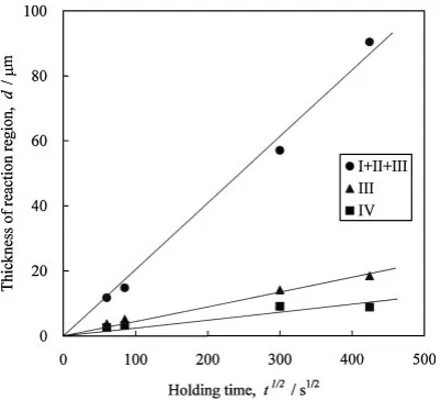
The configuration of the interfacial microstructures in Fig. 2 was well accorded with our previous report.3) In addition, it should be noted that the interface separation described above was not induced in the Ti-20Al alloy/high carbon steel joint bonded at 1173 K. Figure 3 shows the relationship between the holding time and the thickness of regions I to IV in the joint bonded at 1173 K. The horizontal axis represents square root of total holding time of the bonding and heat treatments. Furthermore, the thickness expressed by ‘‘I + II + III’’ corresponds to the diffusion distance of Fe into the Ti-20Al alloy, since it is thought by previous research2,3) that the initial interface is located between regions III and IV in Fig. 2. The growth of each region showed the linear relationship for square root of the holding time. This means that the Ti-20Al alloy is attached firmly to the steel at a heating temperature of 1173 K and the diffusion of constituent elements is retained even after the prolonged heat treatment.
3.2 Interfacial microstructures at a heating temper-ature of more than 1273 K
Figure 4 shows SEM micrographs of the interface in the Ti-20Al alloy/high carbon steel joint bonded at 1273 K. The holding time in Figs. 4(a) and 4(b) is 0.9 and 1.8 ks,
respectively. These interfacial microstructures were approx-imately equal to those in Fig. 2 and, thus, regions III and IV in Fig. 4(b) were identified as TiC and ferrite layers, respectively. The products, which were formed by the diffusion of Fe into the Ti-20Al alloy, were also observed.
In Fig. 4(a), the shape of the joint was kept after the bonding treatment. However, the joint bonded at 1273 K for 1.8 ks broke in the vicinity of the interface and showed the separation phenomenon, as shown in Fig. 4(b). The fracture position was between regions III and IV. Some dust such as resin and grinding swarf lodged in this position, since the Ti-20Al alloy and the steel were restored to the shape of the joint after the bonding treatment. The interface separation was also recognized in the joint bonded at 1273 K for 3.6 ks.2,3)As compared to Fig. 2, the bonding treatment was conducted with the same heating and cooling rates, whereas only the heating temperature was different. Considering the dependency on the holding time at 1273 K, it seems that the thermal stress occurring in the bonding process has little influence on the interface separation. On the other hand, it is noteworthy that there were voids along the interface in Fig. 4(a). Although the formation of the voids is likely to be affected by polishing and etching for microstructure obser-vations, these existences may be closely connected with the interface separation behavior.
The interfacial microstructure of the joint bonded at 1323 K for 0.9 ks is presented in Fig. 5. Two white arrows in the figure indicate the position of the space. The holding time required to induce the interface separation was shorter than the case in Fig. 4.
Figure 6 shows the relationship between the heating temperature and the thickness of reaction regions in the Ti-20Al alloy/high carbon steel joint bonded at 1173 to 1423 K for 3.6 ks. Regions I to IV in the figure correspond to those in Fig. 2, and the region expressed by ‘‘I + II + III’’ means the diffusion distance of Fe into the Ti-20Al alloy as already mentioned. In the TiC layer in region III, the thickness appears to become slightly thin with an increase in the heating temperature. The ferrite layer in region IV also denoted the same tendency. If the diffusion proceeds during the bonding treatment, the TiC and ferrite layers should be Fig. 3 Relationship between holding time and thickness of regions I to IV
shown in Fig. 2. Ti-20Al alloy/high carbon steel joint was fabricated at 1173 K for 3.6 ks and then heat-treated at 1173 K for up to 176.4 ks. Horizontal axis represents square root of total holding time of bonding and heat treatments.
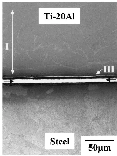
[image:3.595.69.270.71.253.2] [image:3.595.306.548.72.248.2]further developed with increasing heating temperature. Therefore, the stagnation of these growths suggests a possibility for the supply disruption of the constituent elements on the holding step in the bonding treatment. In other words, the interdiffusion at elevated temperatures is thought to be cut off by the interface separation. On the other hand, the region expressed by I + II + III grew remarkably with heating temperature. Its thickness exceeded 100mmat a heating temperature of 1423 K. Actually, the needle-shape products were widely formed in the Ti-20Al alloy, as seen in region I in Fig. 7. However, region II, which corresponds to the reaction layer containing Fe, could not be observed in this specimen. The composition ratio of Ti, Al and Fe in the needle-shape products was76:3 : 13:5 : 10:2(mol%), and its Fe content was smaller than that in Table 1. The diffusion
of Fe on the heating step is considered as a reason for the expanding of I + II + III. Since the heating rate up to 1423 K was 0.17 K/s, the diffusion of Fe into the Ti-20Al alloy should arise on the heating step. As described later, the diffusion of Fe is promoted with increasing heating temperature. Furthermore, Fe, which already migrates into the Ti-20Al alloy in the heating and holding steps, keeps on diffusing into the alloy even after the interface separation was induced. This appears to be responsible for the migration and the coalescence of the needle-shape products. Such a phenomenon has been also reported for -Ti phase and Widmansta¨tten structure in the Ti/ferritic stainless steel clad.4)
According to the Ti-Al binary phase diagram in Fig. 8,5) the Ti-20Al alloy transforms fromþ2duplex structure to
single phase structure at about 1273 K. It is known that Fe diffuses rapidly intoand2, and the diffusion coefficient of
Fe intois larger than that into2.6)In addition, the diffusion
of Fe into-Ti is further promoted.7)Therefore, the diffusion flux of Fe into the Ti-20Al alloy (JFe
Ti-20Al) might increase with an increase in the heating temperature. The diffusion coefficient of Fe intois9:21014m2/s at 1123 K,7)and the value is predicted to become larger in a temperature range of more than 1273 K. In contrast, the diffusion coefficients of Ti and Al into -Fe are 4:21015m2/s7) and 1:5 1015m2/s8)at 1373 K, respectively. Ti atoms also contribute to the formation of the thermodynamically stable TiC layer at the interface. Consequently, the diffusion flux of Ti and Al into the steel at more than 1273 K is considerably smaller thanJFeTi-20Al. In other words, Fe atoms in the steel migrate unilaterally into the Ti-20Al alloy. The formation and accumulation of voids resulting from such a unilateral Fig. 5 SEM micrograph of the interface in Ti-20Al alloy/high carbon steel
joint bonded at 1323 K for 0.9 ks.
Fig. 6 Relationship between heating temperature and thickness of regions I to IV shown in Fig. 2. Ti-20Al alloy was bonded to high carbon steel at 1173 to 1423 K for 3.6 ks.
[image:4.595.323.525.70.340.2] [image:4.595.70.269.70.312.2] [image:4.595.67.271.358.547.2]diffusion is considered as a cause of the interface separation. The voids may be regarded as a kind of Kirkendall void, though fast diffusion mechanism of Fe into Ti materials and the position of initial interface should be taken into account.
3.3 Water-quenching from 1273 K
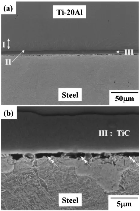
There is a possibility that the interface separation induced in the Ti-20Al alloy/high carbon steel joint is attributed to the interdiffusion across the interface. To prove this assumption, the direct observation of interfacial aspect at elevated temperatures is desired, but it is difficult. For this reason, the joint bonded at 1173 K was quenched into the water from a temperature of 1273 K. The specimen with a special shape shown in Fig. 1(b) was prepared to avoid the occurrence of cracks at the interface in the quenching operation. High carbon steel powders in the copper pipe have a role to coat the joint by sintering at 1273 K. The holding time was 0.9 ks at 1273 K. Figure 9(a) shows a cross-sectional view of the specimen after quenching. There were no cracks caused by quenching and the shape of the joint was retained. An enlarged optical micrograph of the central area in this specimen was presented in Fig. 9(b).
It seems that the cooling rate was somewhat reduced by the existence of the copper pipe and the evacuated silica tube, since the steel did not show a martensitic structure. However, the steel showed a Vickers hardness of about 400, and this value was higher than that in the joint cooled in the furnace (Hv = about 250). Figure 10 shows SEM micro-graphs of the interface in the joint after quenching. The joint had the reaction products indicated by I and II, which were formed by the diffusion of Fe into the Ti-20Al alloy, and the TiC layer indicated by III in the vicinity of the interface. The voids indicated by double arrows were also formed between the steel and the TiC layer. This aspect is similar to Fig. 8 Phase diagram of Ti-Al system.
[image:5.595.310.543.71.422.2]Fig. 9 (a) Cross-sectional view of Ti-20Al alloy/high carbon steel joint after quenching into the water from 1273 K. (b) Optical micrograph of the interface in (a).
[image:5.595.75.262.73.319.2] [image:5.595.50.546.643.757.2]Ti-20Al alloy was diffusion-bonded to high carbon steel in the range from 1173 to 1423 K for 0.9 to 3.6 ks in a vacuum to investigate the mechanism of interface separation phe-nomenon. Several joints were heated at 1173 K for up to 176.4 ks in an evacuated silica tube. The main conclusions are summarized as follows.
(1) In the joint bonded at 1173 K, the interface separation did not occur even after prolonged heat treatment. The joint had four kinds of reaction regions in the vicinity of the interface, and these grew in proportion to square root of holding time. (2) The joint bonded at more than 1273 K showed the separation at the interface. The holding time to induce this phenomenon became shorter, as the heating temperature increased. Since the thickness of TiC and ferrite layers formed at the interface hardly changed with an increase in the heating temperature, it is thought that the supply of
Promotion Grant of The Iron and Steel Institute of Japan, and we greatly appreciate their support.
REFERENCES
1) Y. Morizono, M. Nishida, A. Chiba, T. Yamamuro, Y. Kanamori and T. Terai: Mater. Trans.45(2004) 527–531.
2) Y. Morizono, T. Yamamuro and M. Nishida: Mater. Trans.48(2007) 1476–1482.
3) Y. Morizono, Y. Kodama, T. Yamamuro and M. Nishida: Tetsu-to-Hagane94(2008) 251–257.
4) Y. Morizono, M. Nishida, A. Chiba and K. Imamura: Tetsu-to-Hagane 85(1999) 340–345.
5) R. Kainuma, M. Palm and G. Inden: Intermetallics2(1994) 321–332. 6) Y. Mishin and C. Herzig: Acta Mater.48(2000) 589–623.
7) Metals Data Book, ed. by Japan Inst. Metals (Maruzen Co., Ltd. 1993) pp. 20–25.