Mechanical Properties of Insert-Type Electron Beam Welded Joints
of Spheroidal Graphite Cast Iron and Mild Steel
+Shinichi Sekiguchi
1and Fumio Shibata
21Precision Machinery Company, Ebara Corporation, Fujisawa 251-8502, Japan 2College of Science and Technology, Nihon University, Funabashi 274-8501, Japan
With the aim of improving the performance of electron beam welded joints between spheroidal graphite cast iron (FCD700) and mild steel (SS490), we applied insert-type electron beam welding that has a insert metal into the I-type butt welding between FCD700 and SS490. By using pure nickel and austenitic stainless steel (SUS304) as the insert metal, the microstructure and mechanical properties of the welded joints were examined.
Consequently, we found that, with no weld cracks and porosities in the fusion zone, the microstructure of the fusion zone produced by the pure nickel insert-type welding was austenite, while that of the fusion zone produced by the SUS304 insert-type welding was austenite and martensite. The average hardness of the fusion zone produced by the pure nickel insert-type welding and that of the fusion zone produced by the SUS304 insert-type welding were 235 and 393 HV, respectively, showing a decrease in hardening, compared to that of the fusion zone produced by direct welding, 566 HV.
Concerning the insert-type welded joints, the average tensile strength of the pure nickel welded joint was 425 MPa, while that of the SUS304 welded joint was 443 MPa. The average joint efficiency of the SUS304 welded joint against the mild steel base metal was 84%, showing improvement, compared to that of the directly welded joint, 72%. The impact values of the insert-type welded joints showed almost the same values as those of the directly welded joint. Moreover, concerning the insert-type welded joints (welded joints between FCD700 and SS490), the fatigue limit of the pure Ni welded joint and that of the SUS304 welded joint were 266 and 255 MPa, respectively, showing improvement in fatigue strength, compared to the fatigue limit of the directly welded joint (welded joint between FCD700 and SS400), 209 MPa. [doi:10.2320/matertrans.F-M2012818]
(Received February 13, 2012; Accepted May 10, 2012; Published June 27, 2012)
Keywords: spheroidal graphite cast iron, mild steel, electron beam welding, insert metal, microstructure, mechanical properties
1. Introduction
Spheroidal graphite cast iron is regarded as difficult to weld.1)Since spheroidal graphite cast iron has high carbon content, rapid weld cooling through fusion and solidification during the welding process often leads to the formation of chill and martensite, resulting in hardening and cracking. In addition, the large amount of gas generated during the welding process may form blowholes, causing a significant decrease in mechanical strength. These factors contribute significantly to the difficulty of welding cast iron. Recently, however, welds and composites of spheroidal graphite cast iron and steels have been studied for improvements in functionality and cost efficiency.2) Various approaches to fusion welding between spheroidal graphite cast iron and steels have been reported.39)
Electron beam welding can provide higher energy density than other welding methods and minimize the thermal effect on base metals. Based on this feature, electron beam welding between gray cast irons or between spheroidal graphite cast irons has been reported.1021)
The authors previously examined the microstructure and mechanical properties of direct, I-type butt, electron beam welding between spheroidal graphite cast iron and mild steel.22) The examination showed that the microstructure in the fusion zone exhibited acicular martensite and that the hardness of the fusion zone increased significantly. In some cases, weld cracks and porosities were observed in the fusion zone. The tensile strengths of the welded joints were lower
than those of the base metals. These joints fractured in the fusion zone and at the transition zone of fused material to unaltered mild steel.
In this study, electron beam welding was conducted with the aim of preventing weld cracks and porosities in the fusion zone and improving the metallurgical and mechanical properties of the fusion zone. Electron beam welding was performed by inserting each of several insert metals into the butt surface of spheroidal graphite cast iron and mild steel. Then, the microstructure and mechanical properties of insert-type electron beam welding were examined. The mechanical properties of the welded joints also were examined by comparing them with those of the directly welded joints reported previously.22)
2. Experimental Procedures
Table 1 shows the chemical compositions and mechanical properties of the base metals and insert metals. Spheroidal graphite cast iron (equivalent to FCD700, JIS G5502) and mild steel (equivalent to SS490, JIS G3101) were used as base metals. Pure nickel and austenitic stainless steel (SUS304, JIS G4305) were used as insert metals. Selection of insert metals was based on nickel (Ni) and chromium (Cr) content. Nickel does not harden when cooled rapidly and thus prevents weld cracks. Therefore, insert metals containing Ni are found to be useful for preventing hardening of fusion zone and the resulting weld cracks. Cr is strong deoxidizing element. Insert metals containing Cr are effective in removing the oxygen that might lead to production of porosities in fusion zone.
+This Paper was Originally Published in Japanese in J. JFS 83 (2011)
371377.
Welding tool was a 6 kW high-voltage, high-vacuum electron beam welding machine (all vacuum type). Immedi-ately before welding, the base metals were demagnetized, and the butt surface was degreased with methyl ethyl ketone. As shown in Fig. 1, electron beam welding was performed by inserting an insert metal into the I-type butt weld surfaces, and also with both ends of base metals being lightly held with fixtures. The dimensions of the base metals were 18©200©200 mm, while those of the insert metals were 0.5©18©200 mm.
Test specimens were joined with two-pass welds (down-ward penetration welding). Table 2 shows the welding conditions. The welding conditions ensure that the shape of fusion zone will be formed parallel bead18) and that bead width will be same both top and bottom. Accordingly, between pure Ni and SUS304 with a difference in thermal conductivity, the pure Ni insert-type welding required slightly more welding heat input than the SUS304 insert-type welding. (In this paper, the term “pure Ni welding” refers to use of pure Ni insert metal, and the term “SUS304 welding”refers to use of SUS304 insert metal.)
The welding microstructure was microscopically observed by cutting the bead transversely, polishing the cut surface, and then etching the fusion zone surface with 10% aqueous solution of chromic acid and the treating surface of the heat effected zone and base metals with 4%nital. Furthermore, the chemical analysis of the fusion zone was conducted.
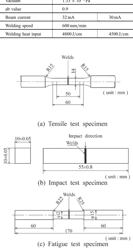
For material tests, a Micro Vickers hardness tester (with a HV of 0.3) was used to measure the hardness at 0.1 mm pitch in the weld cross section. Tensile tests (using the test specimens No. 4, defined by JIS Z2201 “Test pieces for tensile test for metallic materials”), Charpy impact tests (Non-notch, 10©10©55 mm, at test temperatures of 77 to 373 K), and rotary bending fatigue tests (at a rotational speed
[image:2.595.54.549.85.179.2]of 3000 min¹1) were carried out to determine the mechanical properties of the welded joints. Figures 2(a), 2(b) and 2(c) show shapes of material test specimen. The material test specimens were sampled at right angles to weld line, followed by machining. The surface of the welded joints
Table 1 Chemical compositions and mechanical properties of base metals and insert metals.
Materials
Chemical composition (mass%) Tensile
strength (MPa)
Elongation (%)
C Si Mn P S Mg Cu Ni Cr C.E.
Base metal
FCD700 3.75 2.67 0.24 0.02 0.004 0.043 0.62 ® 0.04 4.65 790 6
SS490 0.16 0.16 0.95 0.017 0.006 ® ® ® ® ® 528 37
Insert metal
Pure Ni 0.01 <0.001 0.18 ® 0.001 ® 0.01 99.7 ® ® 500 43
SUS304 0.06 0.41 1.19 0.034 0.009 ® ® 8.30 18.05 ® 592 69
200
FCD700
Electron beam
100 100
18
(unit:mm) Insert metal
1)Pure Ni 2)SUS304
SS490 Welding direction
0.5
Fig. 1 Joint configuration with insert metal.
Table 2 Welding conditions by insert-type welding.
Insert metal Pure Ni SUS304
Number of passes 2 passes
Acceleration voltage 150 kV
Vacuum 1.33©10¹2Pa
ab value 0.9
Beam current 32 mA 30 mA
Welding speed 600 mm/min
Welding heat input 4800 J/cm 4500 J/cm
[image:2.595.47.299.86.351.2] [image:2.595.312.541.263.697.2]fracture in tension and impact was observed with a scanning electron microscope (SEM) and surface analysis with EPMA.
3. Results and Discussion
3.1 Welding microstructure and hardness distribution
Figure 3 shows the microstructures of the upper parts of the cross-sectional beads of the direct welding (a) and the SUS304 welding (b). In both cases, excessive convexity was formed on the weld bead. For the direct welding, weld bead overlap was observed. The width of the excessive convexity was larger than that for the SUS304 welding.
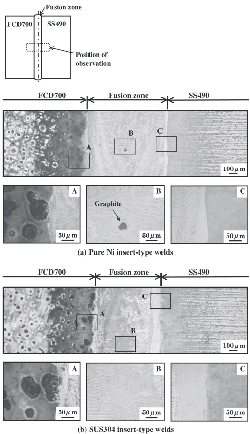
Figure 4 shows the insert-type welding microstructures. The microstructures in both pure Ni and SUS304 fusion zones exhibit the growth of dendrite toward the center of the fusion zone from the bonds of the base metals. Near the bond of mild steel in the fusion zone, the microstructure was different from that at the center. In the pure Ni fusion zone, graphite was observed in the center believed to be a residual of graphite in spheroidal graphite cast iron that was partially unmelted in the pure Ni fusion zone. On both spheroidal graphite cast iron and mild steel sides, the microstructure in the heat-affected zone showed no difference between the different insert metals. The spheroidal graphite cast iron in the heat-affected zone exhibited a mixed microstructure consisting of acicular martensite and ledeburite around the graphite.
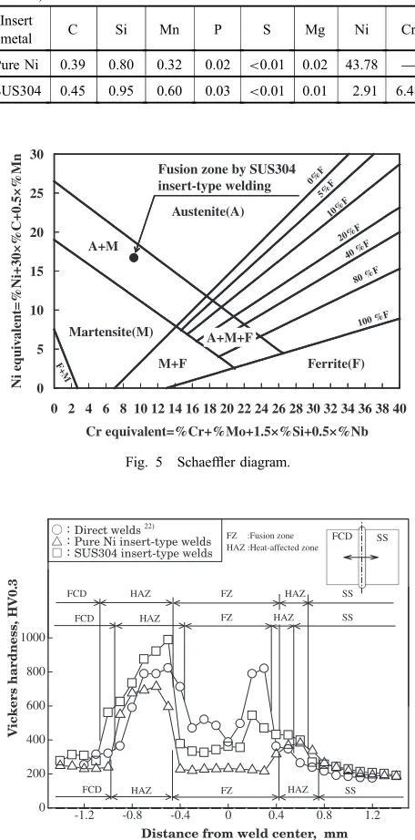
Table 3 shows the results of the chemical analysis of the fusion zones. In the pure Ni fusion zone, the Ni content dropped to 43.78% from 99.7%, which is the original Ni content of the insert metal, due to dilution with the base metals. In the SUS304 fusion zone, the Ni content and the Cr content dropped to 2.91 and 6.48%, respectively, due to the same dilution effect of the base metals.
Figure 5 shows the Schaeffler diagram23) of the fusion zones. The Ni-equivalent of the pure Ni fusion zone was 55.64, which is within the austenite region although it is outside the diagram. The Ni-equivalent and the Cr-equivalent of the SUS304 fusion zone were 16.71 and 9.23, respectively. As shown with a solid symbol ( ) in thefigure, the welded point was in the mixed austenite-martensite area.
Figure 6 shows the hardness distributions of the direct welding and the insert-type welding. The average hardness of the fusion zone was 566 HV for the direct welding, 235 HV
FCD700
Fusion zone
SS490 Position of observation Electron Beam
(a) Direct welds 22)
200µm
(b) SUS304 insert-type welds
200µm
Fig. 3 Microstructure of bead crosses section of direct welds and SUS304 insert-type welds.
SS490 FCD700 Fusion zone
(a) Pure Ni insert-type welds
100µm
A
B C
A B C
50µm 50µm
50µm
Graphite
(b) SUS304 insert-type welds
SS490 FCD700 Fusion zone
A B C
A
B C
100µm
50µm 50µm
50µm FCD700
Fusion zone
SS490
Position of observation
[image:3.595.73.523.75.259.2] [image:3.595.305.548.297.719.2]for the pure Ni welding, and 393 HV for the SUS304 welding indicating that the hardness of the fusion zone for the pure Ni welding and the SUS304 welding was lower than that of the direct welding. Particularly, the hardness in the fusion zone for the pure Ni welding was almost equal to that of both base metals. Possibly, this result occurred because the micro-structure in the pure Ni welding fusion zone formed austenite, while the microstructure in the direct welding fusion zone formed acicular martensite. In all cases, the maximum hardness of the fusion zone was observed within about 0.2 mm from the bond of mild steel toward the fusion zone; the value was 820 HV for the direct welding, 323 HV for the pure Ni welding, and 559 HV for the SUS304 welding. While the difference in hardness between the fusion zone and the mild steel in the heat-affected zone was large for the direct welding, it was small for the pure Ni welding and
the SUS304 welding due to the use of the insert metals. On the other hand, a significant increase in hardness was apparent in the spheroidal graphite cast iron in the heat-affected zone; no effect of the insert metals was observed. Potentially, the microstructure of the spheroidal graphite cast iron in the heat-affected zone was the same for all welding types.
3.2 Mechanical properties of the welded joints
Figure 7 shows comparison of the tensile strengths and joint efficiencies by the difference between the base metals and the welded joints. The welded joint tensile test was conducted using eight test specimens for each of the pure Ni and SUS304 welded joints. The tensile strength of the pure Ni welded joint was 402 to 463 MPa, averaging 425 MPa. The tensile strength of the SUS304 welded joint was 430 to 466 MPa, averaging 443 MPa. The average joint efficiencies of the pure Ni and SUS304 welded joints in relation to the mild steel base metal were 81 and 84%, respectively. These values were higher than the average joint efficiency of the directly welded joints (72%).
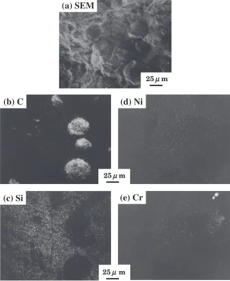
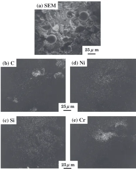
[image:4.595.310.544.69.197.2]Figure 8 shows the SEM image of the tensile fractured surface on the mild steel side of the pure Ni welded joint, as well as the results of surface analysis. A recess in the fractured surface was observed. As shown in the SEM image,
Table 3 Result of chemical analysis of fusion zones by insert-type welding.
(mass%) Insert
metal C Si Mn P S Mg Ni Cr
Pure Ni 0.39 0.80 0.32 0.02 <0.01 0.02 43.78 ®
SUS304 0.45 0.95 0.60 0.03 <0.01 0.01 2.91 6.48
0 5 10 15 20 25 30
0 2 4 6 8 10 12 14 16 18 20 22 24 26 28 30 32 34 36 38 40
Cr equivalent=%Cr+%Mo+1.5×%Si+0.5×%Nb Ni equi v alent=%Ni+30×%C+0.5×%Mn Austenite(A) A+M Martensite(M) M+F A+M+F Ferrite(F) F+M 0%F 5%F 10%F 20%F 40 %F 80 %F 100 %F Fusion zone by SUS304
insert-type welding
Fig. 5 Schaeffler diagram.
-1.2 -0.8 -0.4 0 0.4 0.8 1.2
0 200 400 600 800 1000
Distance from weld center, mm
FCD SS
V
ickers hardness, HV0.3
Direct welds 22)
Pure Ni insert-type welds SUS304 insert-type welds
FZ
FCD HAZ SS
FZ HAZ SS D C F HAZ FZ HAZ
FCD HAZ SS
HAZ
FZ :Fusion zone HAZ :Heat-affected zone
Fig. 6 Vickers hardness distribution of direct welds and insert-type welds.
0 100 200 300 400 500 600 700 800 50 60 70 80 90 100 T
ensile strength, MPa
Ni welded joint Direct 22)
welded joint SS
490 FCD
700 SS 22)
400 Welded joints Base metals Tensile strength Joint efficiency SUS304 welded joint Joint efficiency , %
Fig. 7 Comparison of tensile strength and joint efficiency of base metals and welded joints.
(a) SEM
25µµm
(b) C
(c) Si
(d) Ni
25µm
[image:4.595.55.283.95.556.2] [image:4.595.310.544.248.436.2]the content of carbon (C) was high in some areas, suggesting the presence of graphite. Contrary to C, silicon (Si) was distributed across the observed surface. Ni also was mostly distributed, but its content was high in some areas. Si was absent in the areas with high Ni content. The presence of spheroidal graphite and the distributions of Si and Ni suggest that the tensile fracture occurred at the bond of spheroidal graphite cast iron.
Figure 9 shows the SEM image of the tensile fractured surface on the mild steel side of the SUS304 welded joint, as well as the results of surface analysis. As shown in the SEM image, the fractured surface of the joint mainly exhibited cleavage fracture. Spheroidal graphite was observed on the fractured surface of the joint. Si was distributed almost uniformly in graphite-free areas. For the distributions of Ni and Cr, the content of Cr was high only in a few areas. C was also observed in the areas with the presence of Cr, suggesting the formation of chromium carbide.
Figure 10 shows the area reduction of the welded joints after weld testing. For the directly welded joints, the area reduction was 0%in the spheroidal graphite cast iron and the fusion zone. In the mild steel base metal, it increased with the distance from the fusion zone. For the pure Ni and SUS304 welded joints, the area reduction was 0% in the spheroidal graphite cast iron base metal, 0.89% in the pure Ni fusion zone, and 0.53% in the SUS304 fusion zone. It increased significantly from the fusion zone toward the mild steel base metal.
Thesefindings indicate that the tensile strength of the pure Ni and SUS304 welded joints is higher than that of the directly welded joints because of the prevention of fusion
zone hardening and the improved microstructure. For the pure Ni and SUS304 welded joints, plastic deformation was observed in the fusion zone and the mild steel base metal of the test specimens after the tensile test. This result suggests that the fusion zone of the pure Ni and SUS304 welded joints deformed in the same manner as the mild steel base metal during the tensile test. It is estimated that, since the pure Ni and SUS304 welded joints did not fracture in the fusion zone and at the bond of mild steel, their strength was higher than that of the directly welded joints. At the same time, no plastic deformation was observed in the spheroidal graphite cast iron base metal for both joints. This fact suggests that the fusion zone and the spheroidal graphite cast iron base metal deformed differently during the tensile test, resulting in the fracture of the joints at the bond of spheroidal graphite cast iron.
Figure 11 shows the relation between the impact value and the test temperature for the spheroidal graphite cast iron base metal and the welded joints. The impact values of the pure Ni and SUS304 welded joints exhibited a similar tendency in the test temperature range between 77 and 373 K. At a test temperature of 373 K, the impact value was 6.8 J/cm2for the pure Ni welded joint and 6.7 J/cm2 for the SUS304 welded joint. In the test temperature range between 248 and 373 K, the impact values of the pure Ni and SUS304 welded joints were significantly lower than that of the spheroidal graphite cast iron base metal. There were no significant difference in impact value between the directly welded joints and the pure Ni and SUS304 welded joints.
Figure 12 shows the SEM image of the impact fractured surface on the spheroidal graphite cast iron side of the (a) SEM
(b) C
(c) Si
(d) Ni
(e) Cr
25µµm
25µm
25µm
Fig. 9 EPMA analysis in fractured surface after tensile test. Notes: 1) SUS304 insert-type welding. 2) Tensile fractured surface: SS490 side.
5 0 5 10
0 1 2 3 4 5 6
Reduction of area,
FCD F Z
F Z: Fusion zone
FCD Direct welded joint
Ni insert-type welded joint SUS304 insert-type welded joint
SS SS
Distance from weld center, mm
[image:5.595.309.543.72.195.2]22)
Fig. 10 Reduction of area in each point of welded joints after tensile test.
50 100 150 200 250 300 350 400
0 10 20 30 40 50
Testing temperature, K
Impact value, J/cm
2 FCD700 base metal
Direct welded joint 22)
[image:5.595.53.285.73.357.2]Pure Ni insert-type welded joint SUS304 insert-type welded joint
[image:5.595.315.540.237.355.2]SUS304 welded joint, as well as the results of surface analysis. The cracked side surface was observed. As shown in the SEM image, spheroidal graphite was observed on the fractured surface of the joint. Si was distributed almost across the entire observed surface. The contents of Ni and Cr were high in some areas. Cracks occurred at the bond of spheroidal graphite cast iron during the impact test.
These findings suggest that the impact values of the pure Ni and SUS304 welded joints decreased compared to the spheroidal graphite cast iron base metal, since the spheroidal graphite cast iron in the heat-affected zone was significantly hardened and embrittled regardless of the use of the insert metals.
Figure 13 shows the SN curves of the spheroidal graphite cast iron base metal and the insert-type welded joints. The rotating bending fatigue limit was 266 MPa for the pure Ni welded joint and 255 MPa for the SUS304 welded joint; these values were comparable to that of the spheroidal graphite cast iron base metal (261 MPa). The fatigue limit/ tensile strength ratio was 0.63 for the pure Ni welded joint and 0.58 for the SUS304 welded joint; these values were higher than that of the spheroidal graphite cast iron base metal (0.33). The rotating bending fatigue limit of the directly welded joints22) (FCD700 and SS400 welded joints) was 209 MPa. The insert-type welded joints were found to have improved fatigue strength compared to the directly welded joints.
When the same number of cycles compared, the fatigue strength of the insert-type welded joints was lower than that of the spheroidal graphite cast iron base metal. For the pure Ni welded joint, fatigue fracture under a cyclic stress of 272
to 301 MPa occurred at the bond of spheroidal graphite cast iron for two of six test specimens, in the spheroidal graphite cast iron base metal for one specimen, and in the mild steel base metal for three specimens. For the SUS304 welded joint, fatigue fracture under a cyclic stress of 260 to 297 MPa occurred at the bond of spheroidal graphite cast iron forfive of eight test specimens, in the spheroidal graphite cast iron base metal for two specimens, and in the mild steel base metal for one specimen.
4. Conclusions
Examination of the mechanical properties of insert-type electron beam welded joints between spheroidal graphite cast iron and mild steel showed the following:
(1) In the pure Ni fusion zone, the microstructure exhibited austenite. In the SUS304 fusion zone, the micro-structure exhibited austenite and martensite.
(2) The average hardness of the fusion zone for pure Ni welding (235 HV) and the SUS304 welding (393 HV) was lower than that of the direct welding (566 HV). A significant increase in hardness was apparent in the heat affective zone of spheroidal graphite cast iron.
(3) The average joint efficiencies of the pure Ni and SUS304 welded joints were 81 and 84%, respectively. These values were higher than the average joint efficiency of the directly welded joints. Both the pure Ni and SUS304 welded joints failed at the bond to spheroidal graphite cast iron.
(4) The impact values of pure Ni and SUS304 welded joints resembled those of direct welded joints and were significantly lower than that of spheroidal graphite cast iron base metal.
(5) The rotating bending fatigue limits of the pure Ni and SUS304 welded joints were 266 and 255 MPa, respectively. These values were comparable to that of the spheroidal graphite cast iron base metal (261 MPa). The fatigue limit/tensile strength ratio was 0.63 for the pure Ni welded joint and 0.58 for the SUS304 welded joint and higher than that of the spheroidal graphite cast iron base metal.
(6) The use of either pure Ni or SUS304 insert metal significantly improved the mechanical properties of welded joints.
(a) SEM
(b) C
(c) Si
(d) Ni
(e) Cr
25µµm
25µm
[image:6.595.53.284.69.357.2]25µm
Fig. 12 EPMA analysis in fractured surface after impact test. Notes: 1) SUS304 insert-type welding. 2) Impact fractured surface: FCD700 side. 3) Analysis area: Crack occurrence side.
105 106 107
250 300 350 400
Number of cycles, N
Stress, MPa
~ ~
[image:6.595.322.534.70.204.2]: Pure Ni insert-type welded joint : SUS304 insert-type welded joint : FCD700 base metal
Acknowledgments
The authors are grateful to the research students from the Department of Mechanical Engineering and the Department of Precision Machinery Engineering, College of Science and Technology, Nihon University, for their kind cooperation in the experiments of this study.
REFERENCES
1) Jpn. Weld. Soc.:Yousetsu®Setsugou binran, (Maruzen, 1990) p. 860. 2) K. Asano and T. Noguchi: J. JFS78(2006) 98.
3) T. E. Kihlgren and H. C. Waugh: Welding J.32(1953) 947. 4) S. Hiratsuka, H. Horie, M. Nakamura, T. Kowata, M. Aonuma and T.
Kobayashi: J. JFS70(1998) 860.
5) M. Aonuma, S. Hiratsuka, H. Horie, M. Nakamura and T. Kowata: J. JFS72(2000) 478.
6) T. Suzuki, S. Hiratsuka, H. Horie, S. Moriya, M. Nakamura and T. Kowata: J. JFS77(2005) 314.
7) N. Fujii, J. Takahashi, H. Suzuki and K. Yasuda:Q. J. Jpn. Weld. Soc.
23(2005) 302.
8) S. Hiratsuka, H. Horie, T. Kowata and M. Nakamura: J. JFS78(2006) 112.
9) T. Suzuki, S. Hiratsuka, H. Horie, S. Moriya, M. Nakamura and S. Tada: J. JFS78(2006) 132.
10) F. Shibata: J. JFS69(1997) 391.
11) A. Matting and K. Seifert: Schweiben und schneiden20(1968) 266. 12) F. Shibata, S. Ando and N. Fujisaki:J. Jpn. Weld. Soc.51(1982) 748. 13) F. Shibata and S. Ando: Trans. JWS14(1983) 11.
14) F. Shibata: IMONO56(1984) 532. 15) F. Shibata: IMONO59(1987) 478.
16) K. Tagashira, S. Kamoda and T. Hashimoto:J. S. Precision Eng.53
(1987) 110.
17) F. Shibata and Y. Uchida: IMONO60(1988) 666. 18) F. Shibata: Trans. JWS22(1991) 34.
19) F. Shibata: Trans. JWS22(1991) 40. 20) F. Shibata: Trans. JWS22(1991) 90. 21) F. Shibata: IMONO64(1992) 9.