Crystal Plasticity Simulation Considering Oxidation along Grain Boundary
and Effect of Grain Size on Stress Corrosion Cracking
Yoshiteru Aoyagi
+and Yoshiyuki Kaji
Nuclear Science and Engineering Directorate, Japan Atomic Energy Agency, Naka-gun, Ibaraki 319-1195, Japan
Stress corrosion cracking is a critical concern for light water reactors because it can degrade structural components over a long period. It takes the form of intergranular stress corrosion cracking (IGSCC). Many studies on IGSCC have been conducted over several decades in the past. However, the mechanism of IGSCC initiation and propagation is still not fully understood. In this study, a crystal plasticity model expressing IGSCC is proposed by considering information about the oxidation along the grain boundaries and the failure of an oxidefilm caused by the localization of a deformation. From a crystal plasticityfinite element analysis and an oxygen reaction-diffusionfinite difference analysis based on the presented model, the IGSCC is numerically reproduced, and we discuss the effect of grain size on the crack propagation behavior.
[doi:10.2320/matertrans.MD201126]
(Received August 1, 2011; Accepted October 28, 2011; Published December 7, 2011)
Keywords: intergranular stress corrosion cracking, crystal plasticity, grain boundary, oxygen reaction-diffusion equation, crack propagation, grain size
1. Introduction
Stress corrosion cracking (SCC) in light water reactors (LWRs) has been the cause of significant economic losses as a result of disruptions in power plant availability and the costs associated with SCC mitigation and remediation. Recently, SCC has been found in boiling water reactor (BWR) components, such as core shrouds and primary loop recirculation piping fabricated with low-carbon stainless steels,1,2) as well as in pressurized water reactor (PWR)
components, such as the vessel head penetrations, bottom mounted instrument nozzles, and primary water inlet nozzles of steam generators fabricated with Alloy 600 and its weld metals.35) Consequently, there is incentive for developing quantitative methods for evaluating the reliability and the remaining SCC lifetimes of structural materials in LWRs. Ford and Andresen proposed a crack growth rate prediction model based on the slip dissolution/oxidation mechanism for SCC.6,7) Shojiet al.proposed a theoretical crack growth rate equation based on a theoretical crack tip strain rate formulation and the asymptotic field by considering the solid state oxidation mechanism.811) Bruemmer et al.
analyzed a crack tip oxide film using an analytical transmission electron microscope (ATEM) and reported that the mass transport process in a solid state oxide film could be the key element process for crack growth.12)Staehle also
discussed the visibility of a film rupture event in a tight crack tip.13)In addition, Fukuya et al.14)performed detailed
observations of the crack tip of an active stress corrosion crack in the highly irradiated Type 316 stainless steel of a pressurized water reactor (PWR), which was initiated in the primary system simulated water. They showed that an oxygen atom could be observed up to a distance of around 10 nm from the crack tip. Yamaguchi15)showed that the grain boundary cohesion strength decreased at the 3 grain boundary of an iron-based coincidence site lattice by the segregation of oxygen atoms. Therefore, a solid state
oxidation mechanism might be the critical element process in SCC. Recently, multi-scale modeling has also been performed for the structural materials of a reactor core and the primary coolant components to ensure their safe and reliable operation. In particular, some computational ap-proaches have been proposed for the simulation of intergranular cracks in a polycrystalline aggregate.1618)The
surface of the core shroud of a nuclear reactor is ground to increase the out-of-roundness. Therefore, the surface of the shroud has a severe deformation condition, and the grain size decreases to several microns or less. In the case of the shroud of a nuclear reactor, a crack is generated at the surface of the shroud. SCC in a shroud can be said to start at polycrystalline metals with a grain size smaller than 1 µm, namely, “bulk nanostructured metals”. It is important to evaluate the crack behavior on these bulk nanostructured metals to investigate the SCC of a shroud.
In this work, in order to predict IGSCC numerically, we introduce information about the oxidation along the grain boundaries and the failure of an oxide film caused by deformation localization in a crystal plasticity model. Based on the results obtained from a crystal plasticityfinite element (FE) analysis and oxygen reaction-diffusion finite difference (FD) analysis using the presented model, we discuss the effect of the grain size on the crack propagation behavior.
2. Models of SCC
2.1 Oxygen reaction-diffusion equation
In this study, we assume that oxygen atoms diffuse only along grain boundaries, because the value of the diffusion coefficient of oxygen atoms along the grain boundary is larger than that inside the grain. Considering that the movement of oxygen atoms is caused by a potential originating in a stress that is normal to the plane of the grain boundary and that metals are oxidized by the diffusion of oxygen atoms, a reaction-diffusion equation for the oxygen along the grain boundaries can be written as follows
+Corresponding author, E-mail: aoyagi.yoshiteru@jaea.go.jp
Special Issue on Advanced Materials Science in Bulk Nanostructured Metals
_
C¼Dr2CD
kTr ðCr·Þ KC
2; ð1Þ
whereDis the diffusion coefficient of oxygen atoms,Cis the concentration of oxygen atoms,+is the volume per atom,k is the Boltzmann constant, andTis the absolute temperature. Moreover,·is the normal stress component that applies to a grain boundary, which is expressed by
· ¼T:ðnnÞ; ð2Þ
where T denotes the Cauchy stress tensor and n is the unit vector normal to a grain boundary. In eq. (1), the first and second terms express the phenomena of the diffusion of oxygen atoms and the movement of oxygen atoms caused by the gradient of stress. The third term on the right side represents an oxidation reaction, where K represents the reaction rate coefficient for the oxidation reaction. The occurrence of a second-order oxidation reaction is assumed in this study. Then, the concentration rate of the metal in the grain boundaries is given by
_
M¼ KC2; ð3Þ
whereMis the concentration of metal. Equation (3) expresses the decrease inMoriginating in the oxidation reaction.
2.2 Local criterion of crack progress
When a crack is generated, elastic strain energy is translated into surface energy. In other words, when the density of local elastic strain energy Ee (the elastic strain
energy per unit volume) exceeds the density of surface energy EC (the surface energy per unit volume), a crack
propagates. The density of elastic strain energyEeis given by
Ee¼
Z
TDedt; ð4Þ
where De is the elastic deformation rate tensor. When considering the decrease in metal atoms caused by the oxidation reaction, we modelECsuch as
EC¼2eA 1e
M0M
M0
; ð5Þ
wheree!is the density of the surface energy per unit area,A is the area of the generated crack,eis a numerical parameter expressing the effect of oxidation on cracking, andM0is the
initial concentration of the metal. Equation (5) indicates that a crack always propagates when an amount of 1/e of the metal is oxidized. Whene>1,ECbecomes negative with the
progress of the oxidation. However, in a situation where a crack is not generated,EC>0 is derived fromEC>Eeand
Ee>0.
2.3 Model for failure of oxidefilm
The oxidation films generated on metal surfaces are damaged by the slip deformation of the metal. In order to represent the process where oxygen atoms enter grain boundaries through such damaged oxide films, we propose the following model for the failure of an oxidefilm.
CS¼
X
¡
£ð¡Þsð¡ÞnC
e; ð6Þ
where CS denotes the concentration of oxygen on a metal
surface, £(¡) is the slip rate of slip system¡, s(¡) is the slip
direction vector, andCeis the concentration of oxygen in the
environment. When eq. (6) is used as the boundary condition of eq. (1), the result indicates that oxygen atoms are allowed to enter grain boundaries from new surfaces generated by slip deformation.
3. Crystal Plasticity Model
Information about the stressfield can be obtained using the crystal plasticity model proposed by Peirce et al.19) The
crystal plasticity-type elasto-viscoplastic constitutive equa-tion is written in the form
Tr ¼Ce:DCe:X
a
PðS¡Þ£_ð¡Þ; ð7Þ
where Tr is the Mandel-Kratochvil rate of the Cauchy stress tensor, Ce is the anisotropic elastic moduli, D is the
deformation rate tensor, PðS¡Þ is the Schmid tensor on slip system¡, and£_ð¡Þ is the slip rate. This slip rate,£_ð¡Þ, is given by the rate dependent hardening law of Pan-Rice, as follows:
_
£ð¡Þ ¼£_ð¡Þ
0 sgnð¸ð¡ÞÞ ¸
ð¡Þ
gð¡Þ
1=m; ð8Þ
where£_ð0¡Þdenotes the referential slip rate,¸(¡)is the resolved
shear stress, g(¡) is the flow stress, and m is the strain rate
sensitivity. The evolution equation of flow stress is represented by
_
gð¡Þ¼X ¢
hð¡¢Þj£_ð¢Þj; ð9Þ
where h(¡¢) is the hardening modulus. Various models for
h(¡¢)have been proposed by many researchers, e.g., a model
based on the geometrically necessary dislocation density.20) In this study, to simplify the calculation, we apply the following function of the total slip, £, to the hardening modulus,h(¡¢):
hð¡¢Þ¼h0sech2 h0 ¸s¸0£
; ð10Þ
whereh0is the initial hardening ratio,¸sis the saturated value
of the resolved shear stress, and¸0is the initial flow stress.
4. Results and Discussions
4.1 Computational model
soft material and (b) ¸0=200 MPa, ¸s=260 MPa, and
h0=180 MPa, for a hard material. The nominal stress
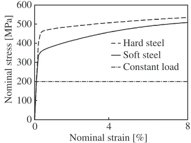
nominal strain curves obtained using calculations without the initial crack are shown in Fig. 2. In these calculations, the coarse grain and fine grain models shown in Fig. 1 are applied to the soft and hard materials, respectively. In this simulation, we establish these parameters so that the yield stress and hardening ratio of the coarse grain model become higher and lower than those of the fine grain model, respectively. In order to investigate the effects of the grain size and mechanical property of the material on cracking, we conduct crystal plasticity calculations using the three different conditions given in Table 1. Note that the actual materials correspond to model A and model C, i.e., model B is a virtual material, used for investigating the effects of the grain size and material property. The other material constants and numerical parameters are given by
D¼0:017m2=s; K¼1000 m3=ðmolsÞ;
D
kT ¼11:1 nm
2=ðsMPaÞ; 2e
A¼8 MPa;
M0¼140:6 kmol=m3; e¼140600; _
£ð¡Þ
0 ¼0:001 s1; m¼0:005
9 > > > > > = > > > > > ;
ð11Þ
Note that we assume that the area of the generated crack is constant because the sizes of the elements for the FEM are almost uniform to simplify the calculation. To maintain an elastic condition macroscopically, a constant load of 200 MPa is applied at the upper end of the specimen. We conduct a
pseudo-three-dimensional computation,21) which assumes a
plane strain condition only in the FE simulation by restricting the three-dimensional deformation caused by the activation of twelve slip systems of the FCC crystal to two-dimensional components on an observation plane. The initial crystal orientation of each grain is decided randomly, while we assume that the diffusion and reaction of oxygen occur only along the initial grain boundaries. Therefore, eq. (1) is discretized usingfinite difference method (FDM) by adopting line elements along the initial grain boundaries. Only the right side of the specimen is exposed to the environment, and the initial oxygen concentrations in the environment and material are 0.001 mol/m3 (about 30 ppm) and 0 mol/m3,
respectively. The oxygen concentration at the surface of the specimen is calculated using eq. (6), and this value is used as a boundary condition for the reaction-diffusion eq. (1). As a result of the generation of a crack, the connection between the FEM nodes along the grain boundaries is cut, and in this case, the density of the elastic strain energy expressed by eq. (4) exceeds the density of the surface energy represented by eq. (5). Both the energy densities are calculated at each node of the FEM. The average value of all the elements contacting a node is used as the density of the elastic strain energy at the node. On the other hand, the density of the surface energy is obtained at lattice points of the FDM, which coincide with the FEM nodes.
[image:3.595.50.288.71.221.2]4.2 Discussion
Figure 3 shows the distributions of the equivalent stress and equivalent plastic strain of model A when the crack length in the horizontal direction reaches 54 µm. In the distributions shown, the bold black lines represent generated 120 µm
30
µ
m
120 µm
30
µ
m
(b) (a)
Fig. 1 Computational models of polycrystals with (a) 225 and (b) 900 grains.
Nominal strain [%]
Nominal stress [MP
a] 500
400
300
200
100
0
0 4 8
Hard steel
Constant load Soft steel 600
[image:3.595.305.550.84.350.2]Fig. 2 Nominal stress versus nominal strain curves.
Table 1 Models of materials used in present simulation.
Number of grains Hardening parameters
Model A 225 ¸0=150 MPa,¸s=240 MPa,h0=500 MPa
Model B 900 ¸0=150 MPa,¸s=240 MPa,h0=500 MPa
Model C 900 ¸0=200 MPa,¸s=260 MPa,h0=180 MPa
(a)
600 MPa 0 MPa
(b)
0.005 0.000
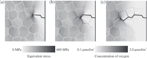
[image:3.595.304.550.84.142.2] [image:3.595.74.262.269.410.2] [image:3.595.48.288.658.726.2]cracks. The generated crack propagates to the left from the initial crack tip. Because plastic deformation occurs locally around the crack tip, residual stress exists at the unloaded area along the generated crack, while the plastic deformation region spreads to the left of the crack tip. On the other hand, Kaji et al.performed a quantitative evaluation of the plastic deformation around an SCC crack in Type 316L low-carbon stainless steel in a BWR simulated environment using the electron backscatter diffraction pattern method and showed that around 1020% of the plastic strain was found at the crack tip and around cracks.22,23)Therefore, concerning the local deformation behavior at the crack tip, the simulation results are consistent with the experimental ones. It is suggested that local deformation at the front of the crack tip affects the configuration of crack propagation. In Fig. 4, the distributions of the equivalent stress and oxygen concen-tration around the initial crack tip are depicted using contour maps and colors for the grain boundary, respectively. Oxygen atoms enter the grain boundaries from the crack tip [see Fig. 4(a)]. The grain boundaries are corroded by oxidation, and the crack propagates further [see Fig. 4(b)]. Then, crack propagation stops [see Fig. 4(c)]. The same processes are repeated, and another crack propagates further. Because oxygen atoms accumulate around the crack tip where the stress value is high, it can be said that the behavior of oxygen atoms is dominated by the gradient of stress in this model. The stress value around the crack tip increases with the extension of the unloaded area because of crack propagation. Hence, the crack starts to branch off as shown Fig. 3. It is predicted that crack branching such as IGSCC occurs because of an increase in the stress around the cracks originating from crack propagation. Tsukadaet al.conducted a post irradiation examination of a sample taken from a stress corrosion cracked region of the outer H6a welded portion of the core shroud from a BWR nuclear power plant and reported that small secondary cracks could be observed around the open main crack with complicated branching. Oxides that mainly consisted of Fe-oxides were observed inside all the cracks, from the opening to the crack tip.24) Thomas et al. characterized stress corrosion cracks in the austenitic stainless steel components from several different BWRs using high-resolution ATEM and showed that the cracking occurred along precipitate-free, non-sensitized grain bounda-ries in highly strained metals and produced many secondary cracks along intersecting boundaries. Moreover, both open cracks and ones that were filled with oxide were found to
contain Cr-rich spinelfilms along the crack walls and Fe-rich spinel toward the crack centers.25)Therefore, from a crystal
plasticity finite element analysis and oxygen reaction-diffusion finite difference analysis based on the presented model, IGSCC with branching secondary cracks that are filled with oxides can be reproduced numerically.
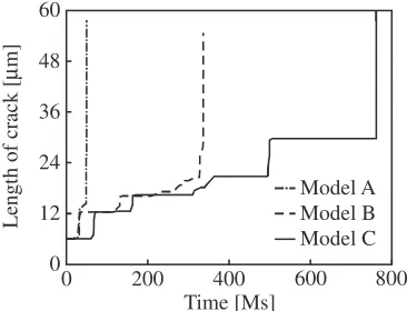
The distributions of the equivalent stress as well as the equivalent plastic strain of models B and C are shown in Figs. 5 and 6, respectively. From Figs. 3 and 5, although the distributions are affected by the initial crystal orientation and shape of the grains, the tendencies of the distributions are similar in cases where the mechanical properties are the same but the grain sizes are different. On the other hand, when the grain size as well as the material properties are different, the distributions of the equivalent plastic strain show different tendencies under similar stress conditions. In the case of Fig. 6(b), plastic deformation occurs only around the crack because of the high yield stress. However, these differences related to the material property and grain size do not affect the shape of the generated crack. Figure 7 shows the relationship between the length of the crack in the horizontal direction and time. We find that the crack propagation rate depends on the hardening parameter and grain size. Thefirst crack propagations of model A and model B, which have the same hardening parameters, occur almost simultaneously. The timing of thefirst progress of a crack in model C, which has a higher yield stress than the other models, is delayed, because plastic deformation hardly occurs in model C. The
(a) (b) (c)
600 MPa 0 MPa
Equivalent stress
2.0 µmol/m3
0.1 µmol/m3
Concentration of oxygen
Fig. 4 Distributions of equivalent stress and concentration of oxygen at (a)t=10.00 Ms, (b)t=31.47 Ms, and (c)t=31.47 Ms.
(a)
600 MPa 0 MPa
0.005 0.000
(b)
[image:4.595.150.448.72.189.2] [image:4.595.307.547.236.408.2]stress concentration occurs around the crack tip of model C, whose yield stress is larger than that of model B, because model B can liberate the elasticity energy by plastic deformation. Therefore, it can be said that oxygen can easily concentrate around the crack tip of model C. However, in the present simulations, considering the failure of the oxidefilm because of slip deformation, because the oxide film of model C is hardly damaged by slip deformation, the amount of oxygen entering the grain boundary is small. On the other hand, the plastic deformation around the crack tip of model B causes the failure of the oxidefilm. As a result, the invasion of oxygen produces oxides in the grain boundary of model B. When the grain size is small, the rate of cracking is small. The propagation of the generated crack is stopped at the triple junction of the grain boundary in this calculation. In the case offine grains, a crack is easy to stop with an increase in the volume fraction of the triple junction. These results suggest that the mechanical property of the material and the grain size affect the timing of the first crack and the rate of crack propagation, respectively. In the present calculation, we assume that the grain size is on the order of several microns. The facts that the timing of thefirst crack is delayed in the case of a high strength material and that the rate of crack propagation is lower when the grain size is small indicates that the IGSCC resistance of ultrafine-grained metals such as bulk nanostructured metals is high.
5. Conclusions
We proposed a crystal plasticity model that considers information about the oxidation along grain boundaries and the failure of the oxidefilm as a result of slip deformation. A crystal plasticity FE analysis and oxygen reaction-diffusion FD analysis based on the presented model were carried out. IGSCC was numerically reproduced and we discussed the effect of the grain size on the propagation behavior of cracks. The conclusions obtained are summarized as follows.
(1) Introducing the oxygen reaction-diffusion model, the local criterion of crack propagation, and the oxidefilm failure model into a crystal plasticity model makes it possible to numerically reproduce the generation and propagation of cracks assuming the occurrence of IGSCC.
(2) Although the crack propagation stops at one point, the crack propagates again as a result of the oxidation corrosion of the grain boundary.
(3) The mechanical property of the material and the grain size affect the timing of the first crack and the crack propagation rate, respectively.
Acknowledgments
This study was financially supported by Grants-in-Aid for Scientific Research on an Innovative Area of “Bulk Nanostructured Metals”, from MEXT, Japan (contact No. 22102007), and the authors deeply appreciate the support received.
REFERENCES
1) T. Shoji: Proc. 11th Int. Symp. Environ. Degradation of Materials in Nuclear Power Systems®Water reactors, (ANS, 2003) pp. 588598. 2) S. Suzuki, K. Kumagai, C. Shitara, J. Mizutani, A. Sakashita, H.
Tohkuma and H. Yamashita: Maintenology3(2004) 6570. 3) P. M. Scott and C. Benhamou: Proc. 10th Int. Symp. Environ.
Degradation of Materials in Nuclear Power Systems®Water reactors, (NACE, 2001) CD-ROM.
4) P. M. Scott and P. Combrade: Proc. 11th Int. Symp. Environ. Degradation of Materials in Nuclear Power Systems®Water reactors, (ANS, 2003) CD-ROM.
5) Nuclear and Industrial Safety Agency (NISA), Feb. 05, (2008). 6) P. L. Andresen and F. P. Ford:Mater. Sci. Eng. A103(1988) 167
184.
7) F. P. Ford:Corrosion52(1996) 375395.
8) T. Shoji, Z. P. Lu and Y. Takeda: ASME Pressure Vessels and Piping Division Conference (ASME PVP 2007/Creep8), (ASME, 2007). 9) T. Shoji, X. P. Lu, Y. Takeda, H. Murakami and C. Y. Fu: ASME
Pressure Vessels and Piping Division Conference (ASME PVP 2008), (ASME, 2008).
10) T. Shoji, Z. P. Lu, N. K. Das, H. Murakami, Y. Takeda and T. Ismail: ASME Pressure Vessels and Piping Division Conference (ASME PVP 2009), (ASME, 2009).
11) T. Shoji, Z. P. Lu and H. Murakami:Corros. Sci.52(2010) 769779.
12) S. M. Bruemmer and L. E. Thomas:Surf. Interface Anal.31(2001) 571581.
13) R. W. Staehle: Proc. 13th Int. Symp. Environ. Degradation of Materials in Nuclear Power Systems®Water reactors, (CNS, 2007) CD-ROM. 14) K. Fukuya, H. Nishioka, K. Fujii and H. Kitsunai: INSS Journal15
(2008) 152161 (in Japanese).
15) M. Yamaguchi:J. Japan Inst. Metals72(2008) 657666 (in Japanese).
16) M. Kamaya and M. Itakura:Eng. Fract. Mech.76(2009) 386401.
17) T. J. Marrow, L. Babout, A. P. Jivkov, P. Wood, D. Engelberg, N.
(a)
600 MPa 0 MPa
(b)
0.005 0.000
Fig. 6 Distributions of (a) equivalent stress and (b) equivalent plastic strain of model C (t=761.2 Ms).
Time [Ms]
Length of crack [
µ
m]
60
48
36
24
12
0
200
0 400 600 800
Model B Model A
Model C
[image:5.595.50.290.70.243.2] [image:5.595.78.261.293.433.2]Stevens, P. J. Withers and R. C. Newman:J. Nucl. Mater.352(2006) 6274.
18) I. Simonovski and L. Cizeli: Proc. Fontevraud7(2007) CD-ROM. 19) D. Peirce, R. J. Asaro and A. Needleman:Acta Metall.31(1983) 1951
1976.
20) Y. Aoyagi and K. Shizawa:Int. J. Plasticity23(2007) 10221040.
21) Y. Aoyagi, N. Horibe and K. Shizawa:Mater. Sci. Forum584586 (2008) 10571062.
22) Y. Kaji, Y. Miwa, T. Tsukada, M. Hayakawa and N. Nagashima: JAEA-Research2007-008(2007) (in Japanese).
23) M. Ando, K. Nakata, M. Itow, N. Tanaka, M. Koshiishi, R. Obata, Y. Miwa, Y. Kaji and M. Hayakawa: Proc. 13th Int. Symp. Environ. Degradation of Materials in Nuclear Power Systems®Water reactors, (CNS, 2007) CD-ROM.
24) The Working Team for Examination Operation of Samples from Core Shroud at Fukushima Dai-ni Unit-3, JAERI-Tech 2004-044, (2004) (in Japanese).