Post-Weld Heat Treatment Effects on Hardness and Impact Strength
of Aluminum Alloy 6061 Friction Stir Butt Weld
Jitlada Boonma
1, Sookkaew Khammuangsa
1, Kanokwan Uttarasak
1,
Jirapan Dutchaneephet
1, Chatdanai Boonruang
1,2and Narin Sirikulrat
1,2,+1Department of Physics and Materials, Faculty of Science, Chiang Mai University, Chiang Mai, Thailand 2Materials Science Research Center, Faculty of Science, Chiang Mai University, Chiang Mai, Thailand
Butt joint friction stir welding (FSW) of aluminum alloy 6061-T651 rolled plate was prepared and the weld specimens were post weld heat treated (PWHT) by solution heat treatment and aging. The hardness, toughness and fracture surface of the PWHT and as-welded specimens were investigated and their relationships were discussed. The effects of FSW are found to soften the nugget zone and thermomechanical affected zone in the as-welded condition, however, the PWHT can provide a full strength recovery in the whole weld specimen. Results from the analysis of relationship of the hardness-tensile strength found that the tensile strength (TS) is linearly proportional to the Vickers hardness number (VHN) with aTStoVHNratio of about 2.75. However, the linear proportion with a negative slope of the hardness-toughness relationship is observed with the characteristic toughness constant of about 40 J for AA 6061. From fracture surface investigation, the unique fracture characteristics comprising double V grooves and double sharp hills with strips equivalent to the cup and cone fracture of the tensile fracture of medium ductile alloys are observed. [doi:10.2320/matertrans.M2015074]
(Received February 23, 2015; Accepted April 27, 2015; Published June 5, 2015)
Keywords: friction stir welding, AA6061, post weld heat treatment, hardness, impact test
1. Introduction
Friction Stir welding (FSW) was developed by The Welding Institute (TWI) in 1991 for welding aluminum alloys in order to overcome problems associated with fusion welding such as porosity, solidification cracking, eutectic melting, etc.1) The FSW is a promising joining method for metals and alloys with no arc melting or shielding gas required and it can be performed on most ductile metals with only a hard stirring pin. However, the FSW is still limited for some types of welding or hard metals. Due to its’ good characteristics, the FSW technology has been developed and widely used in many structural manufacturingfields such as aerospace and airplane, ship, train and automotive industries. The medium strength 6000 series aluminum alloys (AA) which possess good formability, weldability, machinability and high corrosion resistance are the most interested alloys for FSW. The post weld heat treatment (PWHT) on the FSW of the O-condition AA 60612) and AZ31 magnesium alloy friction welded joint3)were reported. Various microstructures and properties of AA 6061 FSW were studied such as relationships of microstructures and fatigue properties of the lap joint FSW,4)microstructure and precipitates investigation by TEM,5) microstructure and mechanical properties,6) PWHT effects on weld properties,6,7) corrosion behavior,8) parameters controlling microstructure and hardness during FSW of AA 6063,9) etc. Because there are no filler alloys used in most FSW, therefore no dilution occurs and the appropriate PWHT after welding of heat treatable AAs can provide a full strength recovery in the whole weldment.2,6) The square butt-welds of AA 6061 with a thickness of 13 mm by using FSW compared with gas tungsten arc welding with different structures in the corroded region were reported.8) A comparison study of the fatigue crack growth of FSW of 6082-T6 and 6061-T6 is reported with similar crack
propagation rates.10) The dissimilar metals of different AA groups FSW such as AA 2219 and AA 6061 was investigated with the minimum hardness observed in the heat affected zone of 6061 alloy and the strength in the weld nugget was found to increase slightly after direct post weld aging.11)The FSW of totally dissimilar alloys were also carried out and various properties and characteristics of weld specimens were reported such as materialsflow in the FSW of Al 6013-Mg,12) the interface characteristics of lap joint of Ti alloy-Al alloy,13) microstructure and mechanical properties of Al 5052-Mg AZ31 butt joint.14)
From most research work on FSW of aluminum alloys, very few topics on impact properties of welded joints are reported. For instance, the totally dissimilar metals FSW of AA 6061 and SS400 low carbon steel was prepared with different process parameters which are found to affect the impact properties with the impact values (or toughness) deviate in the range from below 10 to about 50 joules.15)The low impact values in the order of few joules are observed in the FSW of aluminum alloys (6061 and 7005) composite reinforced with alumina.16)
The aim of the present work was to prepare the 6061-T651 aluminum alloy FSW specimens and the hardness, impact strength and fracture structure were investigated. The relationship of fracture structures and hardness to the tensile and impact strength were analyzed and discussed.
2. Experimental Procedure
The 6061 T6 aluminum alloy rolled plate with a thickness of 6.0 mm was used as the base metal for the butt joint FSW. The composition of the alloy is shown in Table 1. The FSW was carried out using the milling machine Beijing X5032 with a rotation speed and a travelling speed of 1,180 rpm and 600 mm/min respectively. The stirring pin was a cylindrical shape axle with a spherical end smooth surface made of hardened steel with a length of 5.8 mm,
+Corresponding author, E-mail: metal.cmu@gmail.com
6 mm in diameter and a shoulder diameter of 18 mm. Figure 1 shows the schematic drawing of FSW on the straight butt joint of aluminum alloy plates being welded. The rotation direction of the stirring pin, travelling direction and zoning areas of the weld cross section comprising the nugget zone in the center, thermo-mechanical heat affected zone (TMAZ), heat affected zone (HAZ), and the center line HHA for hardness survey measurement are illustrated.
The PWHT of the weld samples was carried out by solution heat treatment at 823 K for 1 h, followed by quenching in cold water at room temperature and aging with four different conditions at 433, 448, 458, and 473 K for 3, 9, and 18 hours. The weld specimens including the base alloy were prepared for hardness and impact tests. The fracture surface of the impact tested specimens was observed under the scanning electron microscope (SEM, JEOL JSM-5910LV).
In this work, the micro-hardness profile along the HHAline across the middle area in the weld specimen cross section as indicated in Fig. 1 was investigated. The hardness of each specific area of both before and after PWHT was measured using the Vickers microhardness tester (STARTEC SNV-1000) with a load of 1.96 N (HV 0.2) and loading time of 10 s.
The weld samples of both before and after PWHT and also the base metal were tested for their toughness by using the 300 joules pendulum impact testing machine (DMC 6705CE, UK) with a Charpy mode at the impact velocity of 5.24 m/s. The specimens for the impact test were prepared in accordance with ASTM E23 with a size of 55 mm©10 mm©6 mm and 2 mm depth V-notch.
3. Results and Discussion
3.1 Hardness tests
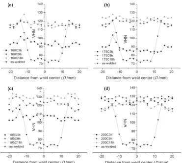
In these experiments, the hardness values of the PWHT samples at each specific aging temperature from 433 K to 473 K are plotted as the hardness profiles through weld and shown in Fig. 2(a)Fig. 2(d). The hardness value of the as-welded sample is plotted in every figure as the comparison
base line with the aged hardened values from heat treatment. The hardness profile of the as-welded sample is observed as the bowl shape with the softening area comprising the nugget zone in the weld centre and TMAZ beside the nugget zone. The hardness of this area decreases from about 116 VHN (T651 in a base metal) to be about 74VHNand the width of about 16 mm in this measuring line is observed. The hardness values in the weld center after welding is similar to that reported in Refs. 5, 8), but they are opposite with the hardness value measured in the O-condition of the FSW in the 6061 alloy2,7) which are the up side down bowl shape. Because no filler alloy is used in the FSW technique, therefore no dilution in the weld area occurs and that results in the constant alloy composition in every zone of the weld specimen. Hence, the hardness values after PWHT in every zone as indicated in Fig. 2(a)Fig. 2(d) increase to be about the same values which are similar to those reported in Refs. 2, 8). The average hardness values of every aging condition at each specific area after PWHT are shown in Fig. 3. The lowest hardness of about 74VHNis the average value from the softened area of the as-welded condition. While the average hardness value of about 116 VHN is observed in the T651 base metal. The peak aged hardening can be observed in the specimen aged at 185°C for 18 h with the average hardness of about 130VHN.
3.2 Impact test
The as-received AA6061, the as-welded and PWHT specimens were investigated for their toughness by using the Charpy impact test and the summary of the toughness are comparatively shown in Fig. 4. The high impact value of about 23 joules which is higher than twice of the base metal is found in the as welded sample. This occurs due to thermo-mechanical heating from FSW which softens the T651 strength of the base metal to be somewhat lower strength similar to the O-condition of the alloy. The toughness is inversely in accord with the hardness values where the higher hardness is the lower impact strength. In the PWHT specimens, the impact value becomes lower because the nugget zone has been strengthened as shown in the hardness profile measurement. After aging at temperatures 448 K to 473 K, the toughness of most specimens decreases to below 10 joules. In these experiments, the lowest value of³6 joules can be observed in the specimens aged at 448 K for 18 h, 458 K for 18 h and 473 K for 9 h. The toughness of both before and after PWHT in this work is rather low when compared with that of the FSW joint of dissimilar metals for AA 6061-steel tested with a C-notch.15)
The impact fracture surfaces of both PWHT and as welded FSW samples and a base metal observed under SEM are shown in Fig. 5. Ductile fracture similar to that of a tensile test can be observed in all specimens. The fracture strips can be observed in the FSW specimens (Fig. 5(b), 5(c)), but can not be observed in the base metal. Because the strips occur due to the severe plastic deformation or a materials flow of two base metal plates being welded at a temperature lower than its melting point arising from the rotating shoulder and stirring pin. In the as welded sample, strips can partly be observed as indicated in Fig. 5(b). In almost whole fracture surfaces of PWHT specimens aged at 448 K to 473 K, the
[image:2.595.46.292.76.258.2]Fig. 1 Schematic drawing of friction stir welding on straight butt joint of aluminum plate being welded showing rotation and travelling direction of the stirring pin (~v) and zoning areas of the weld cross section.
Table 1 Composition of AA6061.
strips are still able to be observed and similar to that shown in Fig. 5(c). The fracture strips in Fig. 5(c) are found to occur in the same direction of the weld travelling direction of the stirring pin. Therefore, each period of the strip is in accord with each round of the pin rotation. The distance between strips of 0.50 mm in Fig. 5(c) is found and this value is almost same as the stirring distance of 0.508 mm which calculated from the rotation speed and travelling speed of 1180 rpm and 600 mm/min.
From the fractograph of the specimen aged at 448 K for 18 h as shown in Fig. 5(c), strips are able to be observed in the whole center fracture surface and appeared as a hill and valley. Observation with SEM at low magnification found
that fracture strips particularly, in the specimens with a peak or near peak aged hardening are clearly observed. The fracture strips occur due to the severe plastic deformation or the metalflow can be observed in 3D rather than 2D as those in previous reports which show the metal flow arising from pin stirring12)or strip lines on the microstructure taken from the weld specimen surface by using an optical microscope or SEM.4,5,7,11) Furthermore, investigation of fracture surfaces and strips of many PWHT specimens shows a similar unique characteristic fracture structure comprising double V-grooves and double sharp hills as the schematic sketch shown in Fig. 6. The deep V-groove corresponding to the high sharp hill is the area close to the shoulder while the shallow
V-Fig. 3 Average hardness values of the PWHT and as-welded FSW specimens comparing to that of the as-received value of the base metal.
(a) (b)
(c) (d)
Fig. 2 Hardness profiles through weld of the as-welded and the PWHT specimens at temperatures (a) 433 K, (b) 448 K, (c) 458 K, and (d) 473 K.
[image:3.595.113.484.66.399.2] [image:3.595.335.520.445.592.2] [image:3.595.76.262.448.588.2]groove corresponding to the low sharp hill is the area at the bottom surface of the specimen attached to the mounting surface of the welding machine. The fracture characteristics are comparable to the cup-cone fracture of the tensile fracture of rod type medium ductile alloys. The stirring and sliding friction of the shoulder on the top contact surface give a much higher heating rate than that arises from the end of the stirring pin at the bottom surface. The high heating rate on the top surface incorporated with the forward sliding velocity of the shoulder and the equivalent backward sliding velocity of the bottom surface with a lower heating rate are expected to result in the appearance of the deep V-groove and the shallow V-groove in the top and bottom parts of the weld fracture respectively.
3.3 Materials strength relationship
Because the alloy used in this study is the T651 strength therefore, thermomechanical heating from FSW gives rise to soften the weld area as the hardness profiles shown in Fig. 2. However, the full heat treatment process can enhance the low hardness in the softened area of weld specimens to the same level as that of the un-welded base metal. These results occur due to the characteristics of the FSW process which does not change the alloy compositions of the FSW specimens from those of the base metal. In order tofind out the relationship of the tensile strength and hardness, the results from the hardness-strength values of various cold working and aging conditions of AA 6061 reported in Ref. 17) are re-plotted with the boundary value at zero hardness as shown in Fig. 7. The yield strength-hardness and tensile strength-hardness relationships can be linearlyfitted and the equations showing their relationships with R2 values of 0.927 and 0.954 can respectively be written as
YS¼2:15VHN ð1Þ
TS¼2:75VHN ð2Þ
whereYSis the yield strength,TSis the tensile strength and VHNis the Vickers hardness number.
The yield and tensile strengths of the base metal with the measured hardness of about 116VHNcan be converted to be 249 and 319 MPa which is rather in good agreement with the TSvalues of AA 6061 T6 indicated in Refs. 6, 18). From the hardness values of the as-welded and PWHT at 458 K 18 h (74 VHN and 130 VHN), the equivalent tensile strengths calculated from eq. (2) are found to be 203 and 357 MPa. Furthermore, when applied the hardness strength relationship
Fig. 5 Fracture surfaces of impact tested specimens taken from camera (left), SEM at low magnification (middle) and SEM at high magnification (right) of (a) the base metal (b) as-welded and (c) peak aged hardening specimens.
[image:4.595.103.496.71.366.2] [image:4.595.64.273.413.567.2]in eq. (2) to the results of hardness and strength measurement of AA6061/20% SiC MMC in Ref. 19), it is found that the measured hardness of 109VHNcan be calculated to be theTS of 299 MPa which is still reasonably close to the measured strength of 287 MPa.
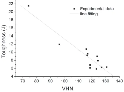
Results from hardness and impact tests of the FSW specimens of both as-welded and PWHT conditions are re-plotted as scattered dots shown in Fig. 8. The hardness and toughness is closelyfitted with a linear line and the slope of about¹0.26. The equation showing the hardness and tough-ness relationship with theR2value of 0.867 can be written as
Toughness¼ 0:26VHNþ40 ð3Þ
where Toughness is the absorbed energy from the impact test (joule). The eq. (3) can be re-written in a general form as
Toughness¼ mðVHNÞ þCS ð4Þ
where m is the slope and CS is characteristic toughness constant of alloys (joule).
The characteristic toughness constant “CS” is the max-imum toughness value for each specific alloy which will be achieved when the hardness decreased to the smallest value. For AA 6061 in this study theCSof about 40 J is obtained.
4. Conclusions
The FSW of aluminum alloy 6061 T651 was satisfactorily
prepared with the softened area found in the TMAZ and nugget zones. The PWHT with an appropriate condition can provide a full strength recovery in the whole weld specimen. Results from hardness-strength analysis show that the yield and tensile strengths in MPa are about 2.15 and 2.75 times of VHNrespectively. From the impact test, the lowest toughness of about 6.2 J is obtained in the PWHT specimen group aged at 458 K for 18 h. Furthermore, the results from the analysis of hardness and toughness show the linear relationship with theR2value of 0.867, a slope of¹0.26 and the characteristic toughness constant of about 40 joules. The fracture structure of the peak aged or near peak aged specimens with the unique characteristics comprising double V-grooves and double sharp hills is observed with strips on the center hill and valley of the fracture surface.
Acknowledgement
This research work was partially supported by the Graduate School, Chiang Mai University and Thailand’s Office of the Higher Education Commission under the National Research University Project. The authors would like to thank the Department of Machine Shop, Lamphun Tachnical College for helping on weld specimen prepa-ration.
REFERENCES
1) W. M. Thomas, E. D. Nicholas, J. C. Needham, M. G. Church, P. Templesmith and C. J. Dawes: Friction stir welding, International patent application, no. PCT/GB92102203 and Great Britain patent application, no. 9125978.8 (1991).
2) N. T. Kumbhar and K. Bhanumurthy: Asian J. Exp. Sci.22(2008) 63 74.
3) S. Fukumoto, D. Yamamoto, T. Tomita, K. Okita, H. Tsubakino and A. Yamamoto:Mater. Trans.48(2007) 4452.
4) X. Xu, X. Yang, G. Zhou and J. Tong:Mater. Des.35(2012) 175183.
5) L. E. Murr, G. Liu and J. C. McClure:J. Mater. Sci.33(1998) 1243 1251.
6) G. Madhusudhan Reddy, P. Mastanaiah, K. Sata Prasad and T. Mohandas:Trans. Indian Inst. Met.62(2009) 4958.
7) K. N. Krishnan:J. Mater. Sci.37(2002) 473480.
8) V. Fahimpour, S. K. Sadrnezhaad and F. Karimzadeh:Mater. Des.39 (2012) 329333.
9) Y. S. Sato, M. Urata and H. Kokawa:Metall. Mater. Trans. A33(2002) 625635.
10) P. M. G. P. Moreira, A. M. P. de Jesus, A. S. Ribeiro and P. M. S. T. de Castro:Theor. Appl. Fract. Mech.50(2008) 8191.
11) R. Priya, V. Subramanya Sarma and K. Prasad Rao:Trans. Indian Inst. Met.62(2009) 1119.
12) P. Pourahmad and M. Abbasi:Trans. Nonferrous Met. Soc. China23 (2013) 12531261.
13) Y. Chen, Q. Ni and L. Ke: Trans. Nonferrous Met. Soc. China22 (2012) 299304.
14) Y. Yan, D. Zhang, C. Qiu and W. Zhang:Trans. Nonferrous Met. Soc. China20(2010) s619s623.
15) T. Chen:J. Mater. Sci.44(2009) 25732580.
16) I. Boromei, L. Ceschini, A. Morri and G. L. Garagnani: Metall. Sci. Tech.24(2006) 1221.
17) M. Mansourinejad and B. Mirzakhani: Trans. Nonferrous Met. Soc. China22(2012) 20722079.
18) J. R. Davis: Metals Handbook, DESK EDITION 2nd Edition I, (Materials Park, Ohio: ASM International, 2003) 464.
19) P. Periyasamy, B. Mohan, V. Balasubramanian, S. Rajakumar, S. Ajakumar and S. Venugopal:Trans. Nonferrous Met. Soc. China23 (2013) 942955.
Fig. 8 The relationship of hardness and toughness of the FSW specimens of both as-welded and PWHT conditions.
[image:5.595.65.274.67.223.2] [image:5.595.64.273.268.424.2]