Effect of Micro-Alloying Elements on Deformation Behavior
in Mg
Y Binary Alloys
Hidetoshi Somekawa
1,+, Yoshiaki Osawa
1, Alok Singh
1,
Kota Washio
2, Akira Kato
2and Toshiji Mukai
31Research Center for Strategic Materials, National Institute for Materials Science, Tsukuba 305-0047, Japan 2Advanced Materials Engineering Division, Toyota Motor Corporation, Susono 410-1193, Japan
3Department of Mechanical Engineering, Kobe University, Kobe 657-8501, Japan
The effect of minor addition of yttrium element on deformation behavior was investigated using MgXat%Y (X=0.01, 0.02, 0.03, 0.04 and 0.05) dilute alloys and pure magnesium with an average grain size of about 50 µm. The stress and strain curves in all the alloys showed a sigmoidal shape in the compression tests, which suggested the formation of{1012}-type twinning due to the lack of slip system. On the other hand, yttrium atom addition of more than 0.03 at%was effective to affect the deformation behavior: a large compressive strain of 0.5 was possible to obtain, and the sub-grained andfine-grained structures were formed even at room temperature in three kinds of alloys. The dominant deformation mechanism in these alloys was the twinning at the beginning of the state and the dislocation slip with further imposed strain.
[doi:10.2320/matertrans.M2013303]
(Received August 5, 2013; Accepted October 15, 2013; Published December 25, 2013)
Keywords: magnesium, solute atom, electron backscatter diffraction observation, deformation twin
1. Introduction
Since magnesium and its alloys are the lightest among all the engineering metallic materials, they have great potential as structural materials in industry. In particular, the use of several magnesium alloys has increased in transport applications, such as automobile, railroad and bike etc., due to weight reduction. The fuel consumption is estimated to increase about 0.9 km/l with a weight reduction of 100 kg in the automotive application.1) However, it is necessary
to develop alloys with good mechanical properties, e.g., strength, ductility and toughness, to sufficiently satisfy both reliability and safety requirements.
Addition of rare-earth (RE) atoms to magnesium is one of the effective and well-known methods for enhancing their mechanical properties. For instance, RE-atoms have much larger atomic radius compared to that of the solvent atom: magnesium. Such a significant atomic size mismatch with magnesium brings about a dramatic increase in strength due to mainly solid solution strengthening.25) In addition, the addition of RE-atoms is known to improve the creep resistance68) as well as to prevent the occurrence of grain boundary sliding.911) Some papers have reported MgY alloys with high creep resistance, and have observed by transmission electron microscopy (TEM) that a number of dislocations are extended in the crept samples.6) Recent
studies by afirst-principle calculation have confirmed that the addition of RE-atoms results in a decrease in the stacking fault energy in magnesium.12)Furthermore, the conventional wrought magnesium alloys show mechanical yield asymme-try due to the formation of a strong basal texture: the yield strength in tension is much larger than that in compression. On the other hand, the addition of RE-atoms is observed to suppress the formation of basal texture, and thus, these alloys exhibit both a symmetric yield strength13,14)and good
formability.15)
Indeed, magnesium alloys containing RE-atoms show superior mechanical properties; however, a reduction in the use of RE-atoms is imperative from economical and ecological points of view. The effect of additional micro-alloying elements on the microstructural evolution, such as grain size refinement and/or the promotion of precipitate nucleation, has been investigated in magnesium alloys.1618) In the former case, a small addition of Zr atoms is well known to refine the grain structures in a cast state.16)In the
latter case, the addition of Ag and/or Ca atoms is reported to enhance precipitation.18)More recently, a minor addition of
Na atoms with 0.3 or 0.09 mass% is shown to be sufficient to affect grain refinement.19,20)However, there are very few
reports regarding the deformation behavior. Thus, in this study, we have selected the Y atom as the solute atom, due to its large solubility, i.e., 11.6 mass% (=3.4 at%), in magnesium.16)The impact of micro-alloying elements on the deformation behavior has been investigated using several compositions of MgY dilute alloys. We have examined the minimum chemical composition to affect the deformation behavior, and have also discussed the deformation mechan-ism of these dilute magnesium alloys.
2. Experimental Procedure
Five compositions of MgXat%Y (X=0.01, 0.02, 0.03, 0.04 and 0.05) dilute alloys and pure magnesium with a purity of 99.94%were used in this study. These MgY alloys were produced by casting, and then were solution-treated at a temperature of 773 K for 2 h. The chemical compositions, which were determined by an inductively coupled plasma mass spectrometry, are listed in Table 1. The alloys had a different composition of Y element, but the other elements were almost the similar. The solution-treated binary alloys and the pure magnesium were extruded at temperatures between 573 and 593 K with an extrusion ratio of 25. The diameter of the extruded bars was 8 mm. These extruded samples were annealed to control the grain size, i.e., an +Corresponding author, E-mail: SOMEKAWA.Hidetoshi@nims.go.jp
average grain size of about 50 µm, under several temper-atures and holding times. The microstructures were observed at the center of the cross-section containing the extrusion and transverse directions (ED-TD) by an optical microscopy. The grain sizes were measured by the linear intercept method21)
counting at least 2,000 grains. The samples for all micro-structural observations were polished with fine SiC papers, diamond slurries and a colloidal silica slurry. The polished samples were etched for several seconds in a solution of 10 mL HNO3 and 30 mL H2O.
The compression tests were carried out in an initial strain rate of 1©10¹3s¹1at room temperature (298 K) for all the samples. The tests were automatically stopped at the strain of 0.5 due to machine limitation. The compression specimens with a height of 8 mm and a diameter of 4 mm were machined from the extruded bars. The compression axes of all the specimens were parallel to the extrusion direction. The deformed microstructures were observed using electron backscatter diffraction (EBSD, in a field emission gun scanning electron microscope (FE-SEM) equipped with an EDAX-TSL EBSD system). Mg0.03Y and 0.05Y alloys were selected for observation of the deformed micro-structures. In each Mg0.03Y alloy, the specimen was separately deformed to plastic strains of 0.2 and 0.5, and the individual regions were observed. In the Mg0.05Y alloy, the specimen was deformed to plastic strains between 0.01 and 0.165 (details of imposed strains are marked in Fig. 2), and the same regions were examined. In this case, at each
imposed strain, the specimen was removed from the testing machine, and then the deformed surface was observed using the EBSD technique. After the observation, the specimen was returned to the testing machine, and then the next selected strain was applied.
The strain rate change compression tests were also performed at room temperature and at elevated temperatures of 323, 348 and 373 K using the Mg0.05Y alloy, where the tests were stopped at the strain of 0.3. The strain rate was changed from 1©10¹4 to 1©10¹2s¹1 at the set strain of 0.05 or 0.15. Except for the test at room temperature of 298 K, the specimens were kept in the furnaces for 3.6 ks at the set temperature, and then the compression tests were performed.
3. Results and Discussion
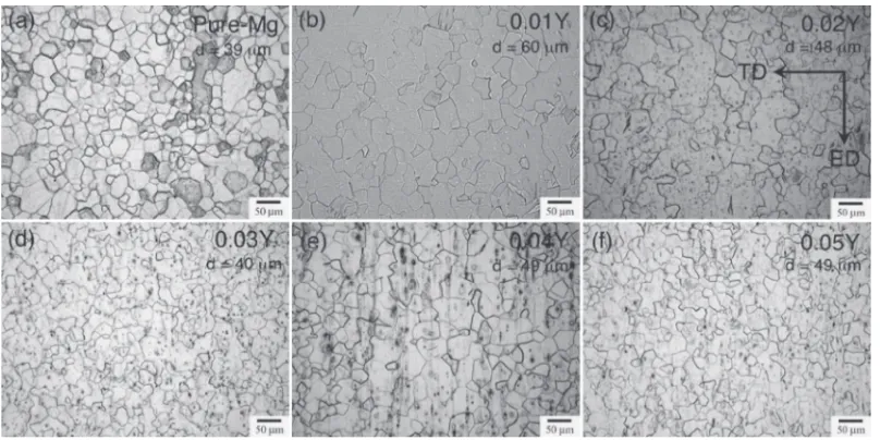
Typical microstructures for all the alloys are shown in Fig. 1. The average grain size, which was measured by the liner intercept method, is added in thisfigure. All the alloys are found to have almost the similar grain size of ³50 µm. These figures show that the grains are not bimodal or elongated, but are equi-axed.
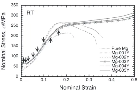
The nominal stress and strain curves of pure magnesium and various MgY alloys in the compression tests are shown in Fig. 2. The features of stress and strain curves are influenced by the addition of Y atom and its chemical composition. The yield strength increases with the addition of Y atoms. All the curves show a sigmoidal shape and a large strain hardening after the yielding; however, the occurrence of strain hardening is suppressed with the addition of a high amount of Y atoms, i.e., more than 0.03 at%. It is also noted that three MgY alloys (0.03Y, 0.04Y and 0.05Y) exhibit similar behavior: (i) the compressive strain extends up to 0.5 and (ii) the strain hardening decreases beyond a compressive strain of³0.15.
[image:2.595.44.292.95.171.2]To scrutinize the deformation behavior at the beginning, i.e., up to an imposed strain of 0.15, the deformed microstructures observed by EBSD of the Mg0.05Y alloy are shown in Fig. 3. Each imposed strain is marked in the
Table 1 The chemical composition in the MgY alloys as measured by inductively coupled plasma mass spectrometry.
Y Fe Si Mn Cu
Mg0.05Y 0.16 (=0.044) 0.002 0.002 0.003 <0.001 Mg0.04Y 0.13 (=0.036) 0.002 0.002 0.004 <0.001 Mg0.03Y 0.09 (=0.025) 0.002 0.002 0.004 <0.001 Mg0.02Y 0.06 (=0.016) 0.002 0.002 0.003 <0.001 Mg0.01Y 0.02 (=0.005) 0.002 0.002 0.003 <0.001
where parentheses indicate the atomic%.
[image:2.595.98.502.560.762.2]stress and strain curves using arrows, in Fig. 2. The corresponding inverse polefigure plots in a specific imposed strain are added in Fig. 4. Figure 3 shows that the
{1012}-type twinning, which is confirmed by EBSD analy-sis, is observed in all the deformed samples: in particular, even the deformed sample with an imposed strain of 0.01. Since there is no twinning before the testing (shown in Fig. 1), it is concluded that this kind of twinning forms during the compression test. The yield strength in compres-sion test of magnesium and its alloys is reported to have a close relation to the formation of twinning, and is expressed with the HallPetch equation.2224) Since the present alloys have a similar grain size and an absence of particles, the difference in yield strength is assumed to be simply due to the addition of the Y atom, i.e., solid solution strengthening.
Figure 3 also demonstrates that the morphology of twinning varies with the increase in plastic strain. Not only the density of twinning increases but also the width of twinning expands with an increase in the imposed strain. This change in microstructural feature can be explained using texture analysis (Fig. 4) and the corresponding stress and strain curves (Fig. 2). Twinning in HCP metals has two kinds of independent mechanism: twinning-nucleation and twin-ning-propagation. While the twinning-nucleation is driven by the local stress state and local atomistic configurations at grain boundaries, the twinning-propagation is driven by long-range stress states across grains. Twinning is well known to nucleate during the plastic deformation due to compensation for the lack of a slip system.25,26)At the plateau region in the
stress and strain curves, Fig. 3(a) indicates that new twins are found to nucleate in the grains, and some twins grow. This behavior indicates that twinning is a mixture of the above two independent mechanisms: the basal texture is maintained, as shown in Fig. 4(a). In the imposed strain of more than 0.1, however, it is difficult to find out new twinning-nucleation, from Fig. 3(b). The twinning-propagation becomes the dominant mechanism, which leads to a dramatic texture change, i.e., accumulation of (1010), as shown in Fig. 4(b). Figure 4(c) reveals that the crystal rotation due to twinning-propagation tends to be suppressed with further increase of the imposed strain. The rapid strain hardening is found to occur in compression for this crystal rotation. The occurrence
of strain hardening after the plateau region results from the interaction between dislocations and twin boundaries, which have been observed using TEM elsewhere.2729) These texture changes during compression tests have been con-firmed in magnesium and its alloys.30,31)Thus, the addition of
Y atoms does not bring about dramatic differences at the beginning of deformation.
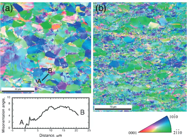
Meanwhile the conventional wrought magnesium alloys show a breaking strain of around 0.20.3 in the compression tests,16,25)specific MgY alloys, such as Mg0.03Y,0.04Y and 0.05Y, have superior compressive deformability. To understand the deformation behavior on further plastic deformation, i.e., plastic strain of more than 0.15, the deformed microstructures by EBSD observation in the Mg 0.03Y alloy are shown in Fig. 5; (a) imposed strain of 0.2 and (b) 0.5. Figure 5(a) shows that the microstructural feature is the same as that in the Mg0.05Y alloy: a few existences in twinning and the conspicuous color variation, for example, are indicated by the solid line AB. A quite low fraction of twinning indicates that the crystal rotation is no longer needed to continue the plastic deformation. In exchange for twinning formation, another mechanism plays an important role in deformation. The accumulation of misorientation along the line is inset in Fig. 5(a). This profile exhibits a slight change in the misorientation, which suggests the formation of sub-grains due to the activation of some degree of multiple slip or cross-slip. This microstructural evolution is observed in the deformed magnesium alloys.32)
The microstructure is found to change with more imposed strains: formation offine-grained structures is confirmed even at room temperature in Fig. 5(b). It is interesting to note that the grain refinement due to dynamic recrystallization is observed in pure magnesium at room temperature.33)
However, the imposed strain,¾>4, in the previous study is apparently larger than that in the present result,¾=0.5. Some recent papers have pointed out that the addition of Y atoms brings about a decrease in critical resolved shear stress in the non-basal plane byfirst-principle calculation.34,35)In addition, the addition of Y atoms is reported to promote the formation of stacking faults in the matrix. Furthermore, these points, where the created stacking faults are due to the addition of Y atoms, are the origin of the activation of cross-slip.36,37) Detailed
microstructural observation using TEM will be needed in the future; however, one of the reasons for the formation of fine-grained structures is the activation of cross-slip and/or multiple slip, shown in Fig. 5(a). The analysis from the thermomechanical viewpoints is described in a later section. The nominal stress and strain curves of the Mg0.05Y alloys at the various temperatures in the strain rate change compression tests are shown in Fig. 6; (a) strain rate change at set strains of 0.05 and (b) 0.15. Figure 6 shows that all the curves have a similar feature: strain hardening occurs after yielding, and then theflow stress tends to become constant. Theflow stress is confirmed to go up at the set strain of 0.05 or 0.15. The difference inflow stress,¦·, between the strain rate of 1©10¹4 and 10¹2s¹1 is influenced by the temper-ature and the set strain for strain rate change. To understand the effect of these factors, the variation of flow stress as a function of strain rate is shown in Fig. 7. The flow stress decreases with a higher testing temperature and smaller set
[image:3.595.54.284.66.216.2]Fig. 3 The deformed microstructures by EBSD observation in the Mg0.05Y alloy; (a) imposed strain of 0.01, (b) 0.02, (c) 0.035, (d) 0.055, (e) 0.075, (f ) 0.10, (g) 0.125 and (h) 0.165.
Fig. 5 The deformed microstructures by EBSD observation in the Mg0.03Y alloy; (a) imposed strain of 0.2 and (b) 0.5. Fig. 4 The inverse polefigure images by EBSD observation in the Mg0.05Y alloy; (a) imposed strain of 0.01, (b) 0.055, (c) 0.10 and
[image:4.595.141.455.68.387.2] [image:4.595.94.498.431.498.2] [image:4.595.138.458.535.770.2]strain for strain rate change. The dependence of strain rate on flow stress corresponds to the strain rate sensitivity:m-value. The m-value of strain rate change at a set strain of 0.05 is lower than at a set strain of 0.15. Despite analysis into two strain rate conditions, the strain rate sensitivity is obtained to be 0.015 and 0.023 for the strain rate change at set strains of 0.05 and 0.15, respectively. Thesem-values in the power-law creep equation suggest that the deformation mechanism is likely to lie in the law breakdown regime. The power-law breakdown is usually associated with dislocation glide as the kinetically rate-limiting process underlying deformation, and is developed a common constitutive equation such as;
_
¾¼A½sinhð¡·ÞnD
0exp RTQ
ð1Þ
where A is a constant, · is the flow stress, ¡ is constant (=0.022 for magnesium alloys39)),n is the stress exponent
(=1/m),D0is the pre-exponential factor,Qis the activation
energy and RT is the thermal energy. This deformation
mechanism is known to be observed at lower temperature or in higher strain rate conditions,38)which is reasonable given
the present experiments.
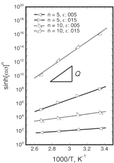
[image:5.595.333.520.65.333.2] [image:5.595.62.277.65.316.2] [image:5.595.53.284.371.518.2]We estimate the activation energy to further discuss the deformation mechanism. The relationship between [sinh(¡·)]n and the reciprocal temperature at a fixed strain
rate of 1©10¹3s¹1is shown in Fig. 8. In this analysis, two kinds ofn-values are used, because then-values are reported to be in the range of 410 in the law creep and power-law breakdown regimes for the metals including magnesi-um.38)The slope of line in thisfigure is the activation energy, which is calculated to be 1733 and 83166 kJ/mol for the strain rate change at set strains of 0.05 and 0.15, respectively. The activation energy in the law creep and the power-law breakdown regimes is reported to be about 230 kJ/mol for magnesium.38) Since the estimated activation energy
(83166 kJ/mol) for the strain rate changing at a set strain of 0.15 is in a similar range, the rate-limiting process is likely associated with dislocation motion. On the other hand, the activation energy (1733 kJ/mol) at a set strain of 0.05 is apparently much lower than that of the power-law creep and power-law breakdown regimes. The activation energy for deformation twinning in magnesium is unknown; however, it is interesting to note that the activation energy in another HCP metal has been reported to be 40 kJ/mol, when the deformation twinning contributes to deformation.40) This result suggests that the deformation mechanism for strain rate change at a set strain of 0.05 competes with the deformation twinning. The imposed strain of MgY alloys affects the deformation mechanisms, and these behaviors are found to consist with the deformed microstructural observations, as shown in Figs. 35.
Finally, we inspect the effect of chemical composition (Y atom concentration) on deformation behavior. Figure 2
Fig. 6 The nominal stress and strain curves of the Mg0.05Y alloy at the various temperatures in the strain rate change compression tests; (a) strain rate change at strain of 0.05 and (b) 0.15.
Fig. 7 The variation offlow stress as a function of strain rate at the various temperatures.
shows that the unique deformation behavior in the compression tests is not attained in pure magnesium and the Mg0.01 and 0.02Y alloys. This result indicates that the value of 0.03 at% is a transition chemical composition to affect the deformation. From the viewpoint of atomistic bonding, the influential range of a large stress field due to the lattice defects, such as dislocations, is reported to be 610b (b: Burgers vector).41) In the case of the Mg0.03Y alloy, if a solute atom would exist individually in the solvent atoms, the distance between each solute atom is estimated to be ³15b, which is the similar range to the above theoretical maximum distance. This indicates that the addition of only 0.03 at% is sufficient to make a change in the deformation behavior in the metallic materials. On the other hand, since the space between the solute atom and the lattice defect apparently becomes long with a decrease in the addition of solute atoms, the solute atom has difficulty affecting the plastic deformation. Thus, the compressive stress and strain behaviors in the Mg0.01 and 0.02Y alloys are the same as those in the conventional wrought magnesium alloys. The reasons for larger strain hardening after yielding and lower compressive deformability in these two alloys are not only the interaction between twinning and dislocation but also the difficulty in activation of non-basal slips.
4. Summary
The effect of minor additions of the Y element and its chemical composition on the compressive deformation behavior was investigated using several MgY dilute alloys and pure magnesium with an average grain size of about 50 µm. The following results were obtained.
(1) The deformation behavior in compression tests was influenced by the addition of the Y element and its chemical composition. The compressive strain was able to attain to 0.5 in the 0.03, 0.04 and 0.05 at%Y alloys. In addition, the strain hardening behavior in these alloys was decreased, when the compressive strain was more than³0.2.
(2) The deformed microstructural observations showed that the {1012}-type deformation twinning formed at the beginning of deformation. With further imposed strain, i.e., more than of 0.2, not only the sub-grained but also the fine-grained structures were formed in the 0.03, 0.04 and 0.05 at%Y alloys due to the activation of cross-slip or multiple slip.
(3) The results of compression tests at temperature ranges (298373 K) indicated that the rate-limiting mechanism varied with the imposed strain. The deformation twinning and dislocation motions were the rate-limiting mechanisms for strain rate change at set strains of 0.05 and 0.15, respectively.
Acknowledgement
The authors are grateful to Ms. R. Komatsu (National Institute for Materials Science) for her technical help. This work was partially supported by the Toyota Initiative on Magnesium alloys.
REFERENCES
1) K. Halada and K. Ijima:Materia Japan43(2004) 264269.
2) A. Kato, A. Inoue, H. Horikiri and T. Masumoto: Mater. Trans. JIM35
(1994) 125129.
3) H. Somekawa and C. A. Schuh:Acta Mater.59(2011) 75547563.
4) S. Miura, S. Imagawa, T. Toyoda, K. Ohkubo and T. Mohri:Mater. Trans.49(2008) 952956.
5) Y. Kawamura, H. Hayashi, A. Inoue and T. Masumoto:Mater. Trans. 42(2001) 11721176.
6) M. Suzuki, H. Sato, K. Maruyama and H. Oikawa:Mater. Sci. Eng. A 252(1998) 248255.
7) B. L. Mordike:Mater. Sci. Eng. A324(2002) 103112.
8) S. M. Zhu, M. A. Gibson, M. A. Easton and J. F. Nie:Scr. Mater.63 (2010) 698703.
9) H. Watanabe, A. Owashi, T. Uesugi, Y. Takigawa and K. Higashi:
Philos. Mag.91(2011) 41584171.
10) M. Mohri, M. Mabuchi, N. Saito and M. Nakamura:Mater. Sci. Eng. A 257(1998) 287294.
11) H. Watanabe, T. Mukai, S. Kamado, Y. Kojima and K. Higashi:Mater. Trans.44(2003) 463467.
12) T. Uesughi and K. Higashi: J. Jpn. Inst. Light Metals54(2004) 8289. 13) J. Bohlen, M. R. Nurnberg, J. W. Senn, D. Letzing and S. R. Agnew:
Acta Mater.55(2007) 21012112.
14) J. Geng, Y. B. Chun, N. Stanford, C. H. J. Davies, J. F. Nie and M. R. Barneet:Mater. Sci. Eng. A528(2011) 36593665.
15) Y. Chino, K. Sassa and M. Mabuchi: Mater. Sci. Eng. A513514 (2009) 394400.
16) ASM Specialty Handbook, Magnesium and Magnesium Alloys, (Materials park, OH, ASM International, 1999).
17) C. J. Bettles, M. A. Gibson and K. Venkatesan:Scr. Mater.51(2004) 193197.
18) C. L. Mendis, K. Oh-ishi and K. Hono:Scr. Mater.57(2007) 485488.
19) F. R. Elsayed, T. T. Sasaki, C. L. Mendis, T. Ohkubo and K. Hono:Scr. Mater.68(2013) 797800.
20) N. Stanford, J. R. Terbush, M. Setty and M. R. Barnett:Metall. Mater. Trans. A44(2013) 24662469.
21) A. W. Thompson:Metallography5(1972) 366.
22) R. W. Armstrong:Metall. Mater. Trans. B1(1970) 11691176.
23) M. A. Meyers, O. Vohringer and V. A. Lubarda:Acta Mater.49(2001) 40254039.
24) H. Somekawa and T. Mukai:Mater. Sci. Eng. A561(2013) 378385.
25) M. R. Barnett, Z. Keshavarz, A. G. Beer and D. Atweel:Acta Mater.52 (2004) 50935103.
26) J. Koike:Metall. Mater. Trans. A36(2005) 16891696.
27) H. Somekawa, A. Singh and T. Mukai:Philos. Mag. Lett.89(2009) 210.
28) J. F. Stohr and J. P. Poirier:Philos. Mag. A25(1972) 1313.
29) B. Syed, J. Geng, R. K. Mishra and K. S. Kumar:Scr. Mater.67(2012) 700703.
30) A. Jain, O. Duygulu, D. W. Brown, C. N. Tome and S. R. Agnew:
Mater. Sci. Eng. A486(2008) 545555.
31) Y. Chino, K. Kimura and M. Mabuchi:Mater. Sci. Eng. A486(2008) 481488.
32) H. Somekawa and C. A. Schuh:Scr. Mater.68(2013) 416419.
33) R. Kaibyshev and O. Stidikov: Z Metallkd.85(1994) 738843. 34) J. A. Yasi, L. G. Hector, Jr. and D. R. Trinkle:Acta Mater.58(2010)
57045713.
35) T. Tsuru, Y. Udagawa, M. Yamaguchi, M. Itakura, H. Kaburaki and Y. Kaji:J. Phys. Cond. Mater.25(2013) 022202.
36) S. Sandlöbes, S. Zaefferer, I. Schestakow, S. Yi and R. Gonzalez-Martinez:Acta Mater.59(2011) 429439.
37) S. Sandlöbes, M. Friák, S. Zaefferer, A. Dick, S. Yi, D. Letzig, Z. Pei, L.-F. Zhu, J. Neugebauer and D. Raabe:Acta Mater.60(2012) 3011 3021.
38) H. J. Frost and M. F. Ashby: Deformation-Mechanism Maps, (Pergamon Press, Oxford, 1982).
39) S. X. Song, J. A. Horton, N. J. Kim and T. G. Nieh:Scr. Mater.56 (2007) 393395.
40) P. G. Oberson and A. Ankem:Int. J. Plast.25(2009) 881900.