Interactive Cellular and Cordless Video
Telephony: State-of-the-Art System Design
Principles and Expected Performance
LAJOS HANZO, SENIOR MEMBER, IEEE, PETER CHERRIMAN, ASSOCIATE MEMBER, IEEE,
ANDEE-LIN KUAN
Second-generation (2G) mobile radio standards have not been designed with video communications in mind, although the employ-ment of error-resilient, constant-bit-rate proprietary video codecs over these systems is realistic. The third-generation (3G) systems are capable of providing higher rates and better communications integrity in support of video applications. This paper advocates the employment of burst-by-burst adaptive transceivers, which are ca-pable of accommodating the time-variant channel quality fluctu-ation of wireless channels. This paper is concluded with a range of performance figures and system design guidelines for wireless systems.
Keywords—Burst-by-burst adaptive video transmission, H.263
codec, joint detection CDMA, MPEG4 codec, power control, 3G systems, 2G systems, video, video over cordless telephones, video telephony, wireless video, wireless video communications.
I. STATE-OF-THE-ART SYSTEMCOMPONENT DEVELOPMENTS
A. Introduction and Outline
The subject of mobile radio communications has reached a state of maturity over the past two decades, as indicated by the excellent monographs by Jakes [1], Lee [2]–[4], Parsons and Gardiner [5], Parsons [6], Pahlavan and Levesque [7], Feher [8], Goodman [9], Prasad [10], Rappaport [11], Garg and Wilkes [12], Gibbson [13], Glisic and Vucetic [14], Verdu [16], and Meyr et al. [15]. Recent third-generation (3G) mobile research has been strongly motivated by the seminal contributions of Viterbi [17], while a range of European contributions were summarized in [18]. These advances have also been featured in the state-of-the-art collection of high-quality contributions edited by Glisic and Leppänen [19] and in various magazine special issues [20]–[24] and other review articles [25]. A range of further narrow-band multimedia system components were reviewed in [26], [27].
Manuscript received September 1, 1998; revised June 12, 2000. The authors are with the Department of Engineering and Computer Sci-ence, University of Southampton, Southampton SO17 1BJ, U.K.
Publisher Item Identifier S 0018-9219(00)08966-0.
This contribution attempts to summarize a range of recent advances in the field of bandwidth-efficient wireless video communications. In this section, we commence our discourse with a brief overview of the wireless scene and, in particular, by considering the video transmission capabilities of the ex-isting and future wireless systems. The geographical variation of the cellular channel capacity is characterized by Section II, as a motivation for invoking burst-by-burst adaptive trans-ceivers [27]–[29]. The nature of co-channel interference (CCI)—which is the most dominant channel impairment in wireless systems—is the topic of Section III, where it is shown that the geographic variation of CCI justifies the em-ployment of multimode transceivers, which are discussed in Section IV. Low-rate video compression aspects are reviewed in Section V, and the performance of the ITU H.263 codec is analyzed in some depth. Our discussions in Sections VI and VII are focused on the performance of reconfigurable video transceivers. Specifically, in Section VI, no power control is used—which is typically the case in cordless telephones, such as DECT and CT2—while in Section VII, power control is employed, which is characteristic of cellular systems, such as GSM [30], IS-136, IS-95, etc. Section VIII proposes a near-instantaneously adaptive or burst-by-burst adaptive code-division multiple-access (CDMA) scheme, which can be invoked in the context of the forthcoming 3G systems, in order to enhance their performance. Lastly, our discussions are concluded in Section IX with a range of system design guidelines. Let us now commence our overview of the range of existing and forthcoming wireless systems and their video transmission capabilities.
B. Second-Generation (2G) Wireless Systems
The existing 2G wireless systems now constitute a mature technology. Although they have not been designed with video communications in mind, with the advent of the specially designed error-resilient, fixed-rate video codecs [27]–[35] proposed by Streit et al., it is nonetheless realistic to provide videophone services over these low-rate schemes. For low-latency interactive videophony these systems have
Table 1
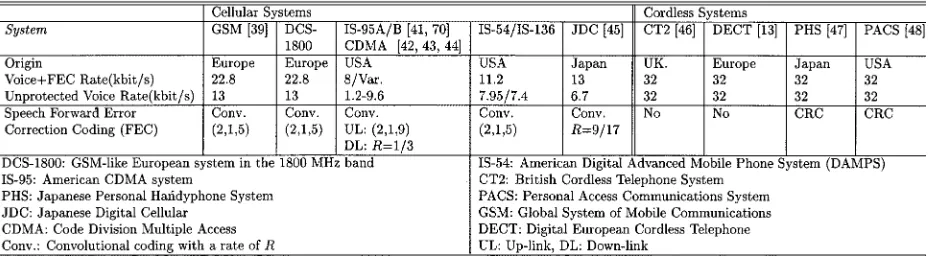
Speech Coding Rates of 2G Mobile Systems
to use an additional speech channel,1 since the typical
mobile radio data channels that are available at the time of writing typically exhibit a higher delay than the speech channel due to the increased interleaving delay required for maintaining a higher error resilience. Therefore, the existing data channels are typically less amenable to interactive real-time videophony. The associated bit rates of the 2G speech systems—which would be, therefore, also applicable to the video channel—are summarized in Table 1, along with their acronyms and an associated background reading concerning the various other parameters of these systems. We note, furthermore, that with the advent of the emerging so-called general packet radio system known as GPRS [37] and the high-speed circuit switched data (HSCSD) [36] channel, the employment of multiple time slots per user becomes possible, which renders the system more amenable to video telephony [27], [38].
Let us consider first the 2G cellular systems represented, for example, by the global system of mobile communications known as GSM [39], [40] and its 1800-MHz carrier-fre-quency “up-converted” version known as the DCS 1800 system, the Pan-American IS-95 (CDMA) scheme [41], the Pan-American IS-54/IS-136 [42]–[44], and the Japanese digital cellular (JDC) arrangement [45] summarized in the left half of Table 1. These large-cell cellular systems have a speech rate of less than or equal to 13 kb/s. By contrast, the cordless telephone (CT) schemes summarized in the right half of Table 1, such as the CT2 [46], the digital European cordless telephone (DECT) [13], the Japanese personal handyphone system [47] (PHS), and the American PACS [48] system, all employ 32-kb/s speech codecs and, hence, are more amenable to video communications at this increased rate.
Apart from their bit rate differences, a further important difference between cellular and cordless systems is that the low-complexity cordless systems typically refrain from using power control, while the more complex cellular systems often operate over hostile channels and usually have quite elaborate power-control schemes. Hence, we will provide expected video performance results for both types of systems. Specifically, in Section VI, no power control is invoked, while in Section VII, power control is employed.
1Provided that this is affordable in capacity terms.
C. Video Aspects
The philosophy of the fixed but programmable-rate proprietary video codecs and systems presented by Streit et al. in [27]–[35] was that irrespective of the video motion activity experienced, the specially designed proprietary video codecs generated a constant number of bits per video frame. This constant bit rate was achieved not by the conventional technique of incorporating bit-rate fluctuation smoothing buffering, which would have a feedback to the bit-rate control scheme of the codec and, hence, would increase the delay of the codec. Instead, the generated bit rate was kept constant by configuring the codecs to identify a fixed number of perceptually most important blocks and quantizing them using a constant number of bits per video frame. Furthermore, the philosophy of [27]–[35] was that in order to cope with the high bit error rate (BER) of wireless channels, in some of the codecs it was necessary to refrain from using high-compression variable bit rate so-called run-length coding techniques, hence, accepting some coding inefficiency. This, however, allowed us to generate a video bit stream exhibiting increased error resilience. For example, for videophony over the GSM system at 13 kb/s and assuming a scanning rate of 10 video frames/s, 1300 bits per video frame have to be generated.2
Additionally, two families of codecs were designed by Streit et al. [27]–[35], one refraining from using error-sensitive run-length coding techniques and exhibiting the highest possible error resilience, and another aiming at the highest possible compression ratio. This fixed-rate approach had the advantage of requiring no bit-rate-smoothing buffering and, hence, exhibiting no objectionable video latency or delay, which would jeopardize lip-synchronization between the voice and video signals [27]–[35].
The fixed bit rate of the above proprietary video codecs is in contrast to the variable rate of the existing standard video codecs, such as the Motion Pictures Expert Group codecs known as MPEG1 [49], MPEG2 [50], and MPEG4 [51], [52], [169]–[171] or the H.261 and H.263 codecs [27], [53] standardized by the International Telecommunications Union (ITU). A distinctive feature of the latter standard codecs is, namely, that the time-variant video motion activity
2A range of video sequences encoded at various constant bit rates between
and the variable-length coding techniques employed result in a time-variant bit rate fluctuation due to their effort to maintain a near-constant perceptual video quality.
In this paper, we summarize a range of techniques, which can be invoked in order to render the family of variable-length coded, highly bandwidth-efficient, but potentially error-sensitive class of standard video codecs—such as the H.261, H.263, MPEG1, MPEG2, and MPEG4 arrange-ments—amenable to error-resilient, low-latency interactive wireless multimode videophony.3 A near-constant bit rate
was generated upon reencoding the video sequence a number of times, until, for example, a so-called macro-block (MB) constituted by four 8 8-pixel video blocks generated the required number of bits. This was achieved upon invoking different quantizers from the legitimate set of quantizers in the H.263 scheme [142]. These measures will be highlighted in more depth during our further discourse.
D. Transmission Issues
Focusing our attention on transmission issues, in Europe, the wireless communications community opted for em-ploying CDMA [8], [10], [14] combined with time-division multiple access (TDMA) and with time-division duplexing (TDD) in the 3G personal communications network (PCN) re-ferred to as the universal mobile telecommunications system (UMTS) [68]. The corresponding personal communications system (PCS) emerging from the currently operational IS-95 system is the so-called cdma2000 arrangement in North America, while the ITU completed the so-called intelligent mobile terminal in the year 2000 recommendation, which is termed as the IMT2000 standard [68].
E. 3G Wireless Systems
1) UMTS and IMT-2000 [60]–[68]: As mentioned above, the radio access scheme of both UMTS and IMT-2000 is wide-band CDMA, and both frequency-di-vision duplex (FDD) and TDD operations are supported. In FDD systems, the uplink (UL) and downlink (DL) signals are transmitted using different carrier frequencies in paired duplex bands. By contrast, the uplink and downlink messages in the TDD mode are transmitted using different time slots. An advantage of the TDD mode is that it can be readily used in applications, where the bit-rate requirements are unbalanced between the two directions, such as in video on demand. Specifically, in such an asymmetric-rate application supported by the FDD mode, either the uplink or the downlink frequency slot would be unexploited, while in the TDD mode, the slots can be assigned on a more flexible basis, potentially doubling the capacity of the link by allocating all time slots in one direction.
The parameters of the FDD and TDD modes are mutually compatible, facilitating the implementation of a dual-mode handset capable of accessing the services offered by both
3We note here that in the wireless community, the terminology
[image:3.612.322.550.54.253.2]“mul-timode” often implies actually “multistandard” operation, such as, e.g., GSM/DECT or DAMPS/IS95. However, in this paper, we use the multi-mode expression in order to indicate that the multi-modem can be configured in a number of operational modes.
Table 2
UTRA/IMT-2000 System Parameters (From [68])
Table 3
Parameters of the cdma2000 System (From [68])
FDD and TDD operators. We note furthermore that recent research advocates the TDD mode quite strongly in the context of burst-by-burst adaptive CDMA modems [69], since the uplink–downlink channel quality similarity can be advanta-geously exploited in order to adjust the modem parameters, such as the spreading factor or the number of bits per symbol on a burst-by-burst basis according to the instantaneous channel quality. This allows the system to more efficiently exploit the time variant wireless channel capacity by invoking a more robust modulation mode under hostile instantaneous channel conditions, whilst transmitting a higher number of bits per symbol during favorable channel conditions.
to video communications due to their higher bit rates than the 2G systems of Table 1.
Both the UTRA and the IMT-2000 systems exhibit a basic chip rate of 4.096 Mc/s, requiring a bandwidth of 5 MHz, when using root-raised cosine Nyquist pulse shaping filters [28] with an excess bandwidth of 0.22. IMT-2000 has an additional lower chip rate of 1.024 Mc/s, corresponding to a bandwidth of 1.25 MHz. Increased chip rates of 8.192 and 16.384 Mc/s are also specified in order to cater for much higher user bit rates ( 2 Mb/s).
2) The cdma2000 System [70]–[72]: The current 2G CDMA-based mobile radio systems standardized by the Telecommunications Industry Association (TIA) in the United States are IS-95-A and IS-95-B [70], [72]. As seen in Table 1, the radio access technology of both systems is based on narrow-band DS-CDMA with a chip rate of 1.2288 Mc/s, which gives a bandwidth of 1.25 MHz. IS-95-A was introduced in 1995, supporting a maximum bit rate of 14.4 kb/s [70], [72]. An enhancement to the IS-95-A standards, known as IS-95-B, was launched in 1998 with the objective of supporting data rates up to 115.2 kb/s [74], [18], [62], while essentially retaining the physical layer of the original IS-95-A system. In order to meet the 3G mobile radio system requirements, recently the TIA has ratified cdma2000 as the Pan-American 3G mobile radio system. However, the frequency bands allocated for the 3G mobile radio systems during the World Administrative Radio Con-ference (WARC’92) were 1885–2025 MHz and 2110–2200 MHz, which have already been partially assigned to the IS-95 system in the frequency bands of 1850–1910 MHz and 1930–1990 MHz. Hence, the cdma2000 system was designed such that it can be overlaid on IS-95, and it is backward compatible with IS-95.
The parameters of the cdma2000 system are summarized in Table 3, which has a basic chip rate of 3.6864 Mc/s that is 3 the 1.2288 Mc/s of the IS-95 system. Hence, the band-width was also tripled to 3.75 MHz. Due to the integer rela-tionship between the associated chip rates, the existing IS-95 infrastructure is capable of supporting the operation of the forthcoming cdma2000 system. Higher chip rates of
1.2288 Mc/s, are also supported in cdma2000,
in order to facilitate transmissions at substantially increased bit rates, supporting, for example, high-rate file transfer and high-resolution video communications. The parameter de-termines the channel coding rate and the channel bit rate sup-ported. In order to support, for example, high-bit-rate video communications, has to be used, and in this sce-nario two different modulation modes may be invoked. In the direct-spread modulation mode, the symbols are spread according to the chip rate and transmitted using a single car-rier, giving a bandwidth of 1.25 MHz. This method is used on both the uplink and downlink. In the multicarrier (MC) modulation mode, the symbols to be transmitted are demultiplexed into separate signals, each of which is then spread at a chip rate of 1.2288 Mc/s. different carrier fre-quencies are used to transmit these spread signals, each of which has a bandwidth of 1.25 MHz. This method is used for the downlink only, since in this case, transmit diversity can
be achieved by transmitting the different carrier frequencies over spatially separated antennas. Similarly to UTRA and IMT-2000, cdma2000 also supports TDD operation, which potentially doubles the capacity of the link, when there is a high proportion of asymmetric-rate traffic. This system was also designed for supporting dual-mode FDD/TDD opera-tion, in order to be able to benefit from the services provided by both FDD and TDD operators.
In cdma2000 there are two types of physical chan-nels, namely, dedicated physical channels (DPHCHs) and common physical channels (CPHCHs). As suggested by the terminology, DPHCHs are used to communicate between the base station (BS) and a single mobile station (MS), while CPHCHs carry information between the base station and several mobile stations. Furthermore, there are two different DPHCHs, namely, the fundamental channel (FCH) and the supplemental channel (SCH), in order to support multiple simultaneous services, such as simultaneous conversations with several parties, file transfers, web browsing, etc. Each channel carries a different type of service and is coded and interleaved independently. However, the number of FCHs is limited to one in any connection, which can be supported by several SCHs.
There are two possible transmission frame durations, namely, 20 and 5 ms. For an FCH transmitted in a 20-ms frame, two sets of uncoded data rates, denoted as Rate Set 1 (RS1) and Rate Set 2 (RS2), are supported. The data rates in RS1 and RS2 are 9.6/4.8/2.7/1.5 kb/s and 14.4/7.2/3.6/1.8 kb/s, respectively. Regardless of the uncoded data rates, the channel coded data rate is 19.2 and 38.4 kb/s for RS1 and RS2, respectively, when the rate-control parameter is . The 5-ms transmission frame only supports one data rate, which is 9.6 kb/s. The SCH is capable of transmitting higher data rates than the FCH, ranging from 1.5 kb/s for to as high as 2073.6 kb/s, when . Blind rate detection [73] is used for SCHs not exceeding 14.4 kb/s, while rate information is explicitly provided for higher data rates. The dedicated control physical channel has a fixed uncoded data rate of 9.6 kb/s on both 5- and 20-ms transmission frames. This control channel rate is about an order of magnitude higher than that of the IS-95 system, and, hence, supports a substantially enhanced system control, which can be advantageously exploited in wireless video communications. Given the above-mentioned bit rates and control channel rates, all 3G systems are amenable to interactive video communications using a wide range of video resolutions and bit rates—pro-vided that the system design guidelines summarized during our further discourse can be followed.
In summary, 3G systems are expected to exhibit a high flexibility in terms of bit rates, mobility, and services. Ide-ally, they are backward compatible with 2G systems while having advanced adaptive features, some of which constitute the topic of our further discourse in this contribution.
Fig. 1. Simulated normalized channel capacity profile of a hexagonal cell without power control, employing a reuse factor of seven—corresponding to six first-tier interferers—a path loss exponent of 3.5, slow-fading frequency of 1 Hz, standard deviation of 6 dB, and six stationary 4-QAM uplink video interferers at random positions within cell boundaries (from [142]).
II. CELLULARCHANNELCAPACITYWITHOUTPOWER CONTROL
In this section, we set out to make it plausible that the channel capacity across the geographic area of a cell varies over a wide range, suggesting that an intelligent multimode video transceiver has potential advantages over nonreconfig-urable transceivers, capable of better exploiting the nonuni-form geographic distribution of the channel capacity offered by the system. Even in the power-controlled cellular—rather than cordless—systems, it is beneficial to configure the trans-ceiver in a robust modulation mode near the fringes of the cell, where more hostile channel conditions prevail. Lastly, burst-by-burst adaptive transceivers [27]–[29] are capable of adapting to the short-term time-variant channel quality fluc-tuations of wireless channels expressed in terms of the BER or transmission burst error rate, irrespective of whether their source was the time-variant co-channel and/or intersymbol interference, slow and/or fast fading, etc. The range of al-ready operational adaptive transceivers was reviewed in the excellent contribution by Nanda et al. [75].
More explicitly, in most mobile radio systems, the channel exhibits Rayleigh fast fading, aggravated by typically log-normally distributed shadowing or slow fading, resulting in a time-variant channel capacity. Lee [76] derived an estimate of the channel capacity in Rayleigh fading environments as a function of the channel signal-to-noise ratio (SNR).
In a cellular frequency reuse structure, the effect of co-channel interference must be included in the channel capacity estimate. Hence, the channel capacity formula
proposed by Lee [76] must be modified by replacing the SNR with the signal-to-interference-plus-noise ratio (SINR), provided that the interference is due to a sufficiently high number of interferers and, hence, can be considered near-Gaussian due to the central limit theorem. When this condition is not met, the above approximation will result in optimistic channel capacity estimates. The adjacent channel interference in these elaborations was neglected since in all of our simulation experiments, a Nyquist excess bandwidth of 50% was used, which provides a sufficiently wide transition band for the receiver filters for this condition to be justified [28]. The SINR is defined as
(1)
where
received signal power; received interference power;
additive white Gaussian noise power within the band-width of the channel.
Table 4
Summary of System Features for the Reconfigurable Mobile Radio System (From [142]) PSA-BPSK: Pilot Symbol Assisted Binary Phase Shift Keying. PSAQAM: Pilot Symbol Assisted Quadrature Amplitude Modulation. FEC: Forward Error Correction Coding. PSNR: Peak Signal-to-Noise Ratio. TDMA/TDD: Time Division Multiple Access/Time Division Duplexing
capacity formula proposed by Lee [76]. The horizontal co-ordinates and indicate the distance from the BS of the 200-m-radius cell, while the location of the highest channel capacity peak in the center of the cell indicates the posi-tion of the BS. Six uplink interferers were used, all of which resided in different co-channel cells of the so-called first tier at random locations, since there were only six users commu-nicating at the same frequency in the same time slot. This explains the nonsymmetric nature of the channel capacity profile in Fig. 1 over the area of a typical—approximately 400-m diameter—microcell, where the co-channel base sta-tions (BS) are 1 km apart. All these propagation condista-tions are summarized in Table 4. Observe in Fig. 1 that the cen-tral portion of the cell exhibits typically higher maximum channel capacity than the fringe areas, which will be ex-ploited by the programmable transceiver of Table 4, using 1–6 bits per symbol signaling. Note furthermore that these maximum channel capacity estimates are reduced propor-tionally by the Nyquist excess bandwidth, for example, in case of a modulation rolloff factor of unity by a factor of two. Let us now concentrate our attention on the effects of co-channel interference inflicted by the adjacent cells using the same set of frequencies—an issue, which further justi-fies the employment of burst-by-burst adaptive transceivers [27]–[29].
III. EFFECTS OFCO-CHANNELINTERFERENCE
The co-channel interference performance and the capacity of various cellular systems were investigated, e.g., by Lee
and Steele in [77]. Our co-channel interference studies have mainly concentrated on the uplink of hexagonal cells with a reuse factor of seven, using an omnidirectional antenna at the center of each cell. This is a commonly investigated cel-lular cluster type, where each BS has six so-called first-tier co-channel interferers, as seen in Fig. 2.
The parameter that affects the co-channel interference most is the position of the interferers, which are constituted by the MSs in an uplink scenario. An interferer, which is moving away from its BS within a co-channel cell in the direction of the serving cell, will inflict an increasing interference. If power control is employed, this is likely to be aggravated by its increased transmitted power. However, in a typical scenario, where users are randomly distributed within a cell, power control is expected to reduce the interference load of the system. In order to investigate how the position of the interferers affects the co-channel interference, the following scenarios were investigated.
1) The least detrimental, i.e., “best” interferer position, where all the interferers are placed as far as possible from the interfered BS. This situation is illustrated for the stipulated propagation conditions of Table 4 in Fig. 3(a) in terms of the SIR versus distance from the BS.
2) Worst case interferer position, where all the interferers are positioned as close as possible to the interfered BS, which is characterized by Fig. 3(b).
Fig. 2. Signal and interference paths for uplink simulations, when interfering users are in the positions to cause minimum or maximum interference, for a seven-cell reuse cluster.
It was found that the SIR difference between the best and worst interferer positions varied, but at the edge of the cell was on the average about 6 dB, which is also demonstrated by comparing Fig. 3(a) and (b). Again, the high-SIR cen-tral portion of the cell provides a higher maximum channel capacity, which will be exploited in terms of better video quality by our programmable transceiver of Table 4. In case of voice-activity detection (VAD) [30] assisted speech trans-missions, the above interference loads are reduced by about 4 dB due to the approximately halved on-air time.
Fig. 3. Simulated average SIR (dB) profile of a hexagonal cell without power control, employing a reuse factor of seven, path loss exponent of 3.5, slow-fading frequency of 1 Hz, standard deviation of 6 dB, 4-QAM modulation, and interference from six stationary video users in co-channel cells (from [142]).
Due to the fast fading and slow fading of both the signal and interference, the instantaneous SINR has a larger vari-ance in interference-limited scenarios. This can be particu-larly adverse when the uplink signal is highly attenuated by a deep fade and, coincidently, the interference is boosted by the fading, resulting in a very low instantaneous SINR. The corresponding SINR profile evaluated across the cell area suggests that an intelligent transceiver can exploit the high channel quality of the central section of the cell, which sup-ports the rationale of this contribution.
[image:7.612.82.267.27.548.2]fluctuations. Most of these phenomena cannot be coun-teracted by the power control scheme alone. For example, power control is unable to combat signal dispersion inflicted by the path-length differences of the various propagation paths. Indeed, powering up in order to improve a particular user’s power budget may disadvantage a number of other users, which in turn require power increments themselves, potentially leading to instability of the system. By contrast, burst-by-burst adaptive transceivers support a “nonde-structive” transceiver adaptation to time-variant channel conditions.
The required relative frequency of transceiver reconfigu-rations still remains to be resolved, however. Ideally, each transmitted symbol ought to be transmitted in the “optimum” modem mode, allowing us to maintain the required transmis-sion integrity expressed in terms of the BER or transmistransmis-sion burst error rate while maximizing the associated number of bits per symbol. This, however, would require a symbol-by-symbol based channel quality estimation, which is unreal-istic in practical terms. By contrast, a call-by-call adapta-tion would be inadequate in transmission integrity terms, since the usual bursty channel error events of the conven-tional fixed-mode modems would be experienced. The actual channel quality fluctuations are a complex function of all the users’ normalized Doppler frequency [30], which predeter-mines the rate of the associated CCI as well as ISI fluctu-ations. An informal insight into the rate of channel quality fluctuations associated with the channel impulse response to be introduced at a later stage in the context of Fig. 13 can be gained, also, by considering the modem mode switching example to be discussed in Fig. 14 of Section VIII-D.
Having informally characterized the propagation environ-ment [30] and justified the utilization of burst-by-burst adap-tive transceivers [27]–[29], let us now focus our attention on video transmission aspects, in particular, the design of an in-telligent multimode videophone transceiver.
IV. SYSTEMDESIGNASPECTS OFVIDEOTRANSCEIVERS
A. State-of-the-Art
The state-of-the-art in this field has been portrayed, e.g., in the special issue [111] based on the invited contributions of [112]–[118]. Specifically, Girod and Färber [112] have been influencing the wireless video communications community and the research trends in the field for years, and in their con-tribution to this issue, they considered feedback-based video transmission arrangements. In an effort to reduce the sen-sitivity of the system to transmission errors, the proposed video decoders invoked a combination of error detection, resynchronization, and error concealment, which are appli-cable to most interframe coding-based video compression standards, such as the H.263 and MPEG4 schemes. In their contribution, Villasenor et al. [113] presented an overview of robust video compression techniques and systems in the context of the MPEG4 standard, for example. Van Dyck and Miller [114] contributed in the field of joint video source and channel coding, an area that has attracted much attention in the recent literature, especially when amalgamating these
standard video-codec-based techniques also with the modem employed.
Gharavi and Alamouti [115] advocated employing bit-error sensitivity motivated video bit stream partitioning, in order to more strongly protect the more error-sensitive synchronization and bit stream syntax-related header in-formation of standard video codecs, such as H.263 and MPEG2, for example. More explicitly, their proposed twin-class error-sensitivity-based partitioning arrangement adaptively controlled the separation of the variable-length coded discrete cosine transform (DCT) coefficients and the above-mentioned synchronization- and header-related bits, in an effort to maintain a near-constant bit rate. The authors invoked the IMT-2000 CDMA system in order to characterize the performance of their proposed arrangement. Hagenauer and his colleagues have pioneered intelligent channel coding techniques [116] over the years, contributing to a vast range of advances in the field. In line with Van Dyck and Miller, in their contribution to this special issue, Hagenauer and Stockhammer [116] concentrate mainly on the employment of joint source and channel coding techniques, emphasizing that the system architecture has to be able to adapt to the hostile channel conditions. Focusing more on transmission aspects, Rohling et al., who have been spearheading many of the recent multicarrier transmission [28], [148] based research initiatives, review a range of aspects associated with high-rate multimedia, multicarrier radio transmissions to mobile receivers. Raychaudhuri, who has been instrumental in the conception and development of wireless asynchronous transfer mode (WATM) systems constituting a tetherless extension of the existing ATM backbone, offered a portrayal of the recent developments in this field. These high-rate WATM systems have the potential of delivering high-quality video to laptop computers, for example. Following a similar line of thought, ATM-based multicode CDMA was favored for the transport of MPEG-2 compressed video services over bandlimited mobile chan-nels by Chang and Lin [118]. Similarly to the contribution by Gharavi [115], twin-class channel coding was proposed in order to protect the header and payload of ATM cells.
B. Multimode Video Transceivers
also attractive for supporting burst-by-burst adaptive duplex operation, since, for example, the downlink channel quality estimate generated by the mobile receiver can be signaled to the transmitter of the BS in the immediately adjacent time slot of the TDD structure. This minimizes the delay between evaluating the perceived channel quality and adjusting the modem mode of the transmitter accordingly. These latency aspects were discussed by Torrance et al. [96], while the associated interference aspects were the topic of [97]. Hence, in this paper we concentrate on employing TDD.
As mentioned above, we target our system design example on a GSM-like H.263-based wireless video trans-ceiver, noting that the design principles related to using multimode transceivers relying on adaptive video buffering and packetization are generically applicable—including, e.g., MPEG4—irrespective of the specific target bit rate or video resolution required. Embedding the system design guidelines in this specific, well-understood GSM-like context is likely to prove more tangible for the potential readership than simply phrasing them in generic terms.
An intelligent multimode transceiver is expected to exploit the potentially higher channel capacity of the central section of the propagation cell of Fig. 1, supporting higher quality video communications under higher SINR conditions while employing more error-resilient, but lower video-quality, modes under reduced SINR conditions near the fringes of the cell. This approach was adopted by Williams et al. [78], [79] on a static basis, although it can be invoked also on a more dynamically adapted burst-by-burst basis, as it is highlighted below.
Based on the observation that the instantaneous channel quality expressed in terms of SINR is time-variant in wire-less systems, such burst-by-burst adaptive multimode, multi-level modems were invented by Steele and Webb at the Uni-versity of Southampton in [80], [81], and [28] for slowly fading wireless pedestrian channels, where the channel fluc-tuations were slow with respect to the transmission burst length. Their work spawned further research in recent years [87]–[95] worldwide. Specifically, Goldsmith and her team [82], [85] at Stanford University, Pearce et al. [90] at York University, Kamio et al. at the University of Osaka and the Ministry of Post in Japan [86]–[89] contributed further to this field.
The proposed schemes provide a means of realizing some of the time-variant channel capacity potential of the fading wireless channel [2], [84], invoking a more robust transmission scheme (TS) on a burst-by-burst basis, when the channel is of low quality. In [91], Torrance et al. derived the analytical upperbound performance of such an adaptive quadrature amplitude modulation (AQAM) scheme over slow Rayleigh-fading channels, while in [94], an unequal protection phasor constellation for signaling the transmis-sion scheme of the modem was proposed. The problem of appropriate power assignment in AQAM modems was discussed, e.g., by Morimoto et al. [88] and by Chua and Goldsmith [82]. We note that AQAM can outperform any of its constituent fixed modem modes in BER terms, since it performs always at least as well as the constituent modem
modes but on average transmits a higher number of bits per symbols (BPS) due to assigning as high a number of bits per symbol under favorable instantaneous channel conditions, as possible, while satisfying the required BER constraints. Furthermore, fixed modems cannot refrain from transition, when the channel quality is low, and, hence, bursts of errors are inflicted, which potentially overloads the error correction capability of the associated forward error correction (FEC) codecs. By contrast, a substantial advantage of AQAM is that it can reduce the number of bits per symbol until the target BER requirement is met. Due to this, the FEC codec benefits from less bursty error statistics, which increases the achievable coding gain.
In [93], a combined BER and BPS based optimization cost function was defined and minimized by Torrance et al.in order to find the required modulation switching levels for maintaining average target BERs of 1 10 and 1 10 , irrespective of the instantaneous channel SNR. The former scheme was referred to as the speech scheme and the latter one as the adaptive data scheme. Since disabling transmis-sion during deep fades results in a controllable latency, in [95] and [98] the latency performance of these schemes was quantified and frequency hopping as well as statistical multiplexing were proposed to mitigate the latency inflicted and to reduce the buffer requirements. The expected per-formance benefits of such burst-by-burst adaptive modems over wide-band channels were evaluated by Wong et al. [99] upon defining a novel channel quality metric based on the mse of the channel equalizer employed.
As seen in Table 4, our design example employed here uses embedded binary Bose–Chaudhuri–Hocquenghem (BCH) coding [141] combined with a reconfigurable pilot symbol assisted (PSA) quadrature amplitude modulation (QAM) modem [28]. Here, we refrain from detailing the BCH coding and QAM issues; the interested reader is referred to [141] and [28] for an in-depth discourse. We note, however, that the performance of the system can be further improved by employing turbo channel coding, which was invented by Berrou et al. [58], [59].
Returning to the proposed multimode video transceiver, which is capable of adapting to time-variant channel con-dition, it can operate under network control in one of four modes, corresponding to 1-, 2-, 4-, and 6-bit/symbol modu-lation schemes. This allows the system to span a wide range of operating conditions in terms of video quality, bit rate, robustness against channel errors, and implementational complexity while exploiting the higher channel capacity of the central region of Fig. 1. For example, the transceiver op-erates using highly bandwidth-efficient 64-level PSAQAM (64-PSAQAM) in a benign indoor cordless environment, where high SNRs and SIRs prevail. The number of modu-lation levels is dropped from 64 to 16, when the portable station (PS) is handed over to an outdoor street microcell, and can be further reduced to four or two in less friendly propagation scenarios. Again, the system parameters are summarized in Table 4.
in-voked in order to ensure that the H.263 codec generated a near-constant bit rate—upon invoking different quantizers from the legitimate set of quantizers in the H.263 scheme [142]—spanning a bit rate range of a factor of 1–6, corre-sponding to the 1–6 bit/symbol QAM modem modes. Hence, the FEC coded signaling rate became 7.3 kBaud (kBd) in all modes. We use here Bd-rate, rather than bit rate, since con-stant bandwidth multimode transceivers maintain a concon-stant Bd-rate but their bit rate varies, depending on the number of bits per symbol transmitted. When opting for a modulation excess bandwidth of 50% and a system bandwidth of 200 kHz, as in the GSM system, the maximum signaling rate be-comes 133.33 kBd. At this signaling rate, INT(133.33/7.3) 18 time slots can be created, where INT indicates the in-teger quotient of the division. Assuming an identical speech signaling rate of 7.3 kBd, nine videophone users can be sup-ported by the proposed scheme in the 200-kHz bandwidth of the GSM system. A range of further system aspects can be inferred from Table 4, but due to space limitations here, we refrain from detailing them; they are left for the interested reader to explore in more depth [27], [142].
Having reviewed the salient features of an intelligent mul-timode transceiver, we emphasize again that our objective was to highlight the system design philosophy, which is ap-plicable not only to the specific system design example used here, but also to arbitrary video bit rates, video resolutions, and a range of other parameters. Let us now briefly consider the aspects of our advocated packetization algorithm, which was detailed in [142]. The algorithm proposed exhibits high flexibility, supporting both automatic repeat request (ARQ), a technique documented by Lin et al. in [143] and packet dropping, although in Sections VI–VIII we will present re-sults for the lower delay, lower complexity scenario of packet dropping rather than retransmitting corrupted video packets. Due to the bit error sensitivity of the H.263 codec, corrupted packets cannot be used by either the local or the remote de-coder since that would result in unacceptable video degrada-tion due to error propagadegrada-tion. Hence, these corrupted packets must be either retransmitted or dropped. For ARQ-assisted operation, the corrupted packets may have to be reencoded at a lower bit rate for more robust retransmission [27], while for video packet dropping, both the local and remote recon-struction buffers are updated by a blank packet. A key as-pect of our proposed regime is, therefore, the provision of a strongly error protected binary transmission packet acknowl-edgment flag [142], which instructs the remote decoder not to update the local and remote video reconstruction buffers in the event of a corrupted packet. This flag can be, for ex-ample, conveniently repetition-coded, in order to invoke ma-jority logic decision (MLD) at the decoder. Explicitly, the binary flag is repeated an odd number of times, and at the receiver the MLD scheme counts the number of binary ones and zeros and decides upon the logical value, constituting the majority of the received bits. These repeated packet acknowl-edgment flags are then superimposed on the forthcoming reverse-direction packet in our advocated TDD regime of Table 4. These system aspects will become more explicit in the context of Fig. 4 during our forthcoming elaborations.
We opted for using an MLD code of MLD(27, 1, 13), im-plying that the 1-bit flag was repeated 27 times and, hence, up to 13 transmission errors can be corrected. This corre-sponds to a channel BER of about 50%, and in our inves-tigations acknowledgment errors were only encountered at video frame error rates of around 100%. The corresponding framing structure was shown explicitly by Keller et al. in [146] and [147] in the context of a TDD/OFDM WATM system, where the superimposed acknowledgment flag was portrayed along with the associated delay ramifications. For a detailed treatise on WATM developments, the reader is re-ferred, e.g., to the work by Raychaudhuri and Wilson [157], [196], [158], and Toh [159]. We emphasize again that the de-sign principles transpiring from this paper in the context of low-rate video codecs are equally applicable to the high-rate WATM arrangements of [146] and [147]. A range of mul-tiple access schemes amenable to variable-rate multimedia statistical multiplexing were proposed, e.g., by Brecht et al. in [160]–[162]. In our proposed system, the associated ac-knowledgment feedback flag is transmitted within a TDD frame duration of 20 ms, which is a small fraction of the 100-ms video-frame refreshment interval encountered in the case of a video frame rate of 10 frames/s.
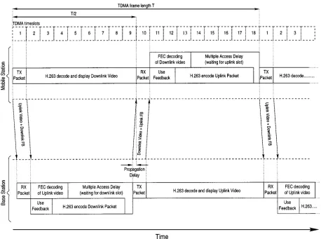
An example of this transmission feedback signaling and timing is shown in Fig. 4 in the context of the system used in our design example. Upon receiving a transmission packet, the transceiver has two tasks to perform before the next trans-mission. First, the video datastream has to be demodulated and FEC decoded in order to check whether there were er-rors in the video stream, since this event has to be signaled in the next transmission burst to the transmitter. The second task is to produce the next video packet for the forthcoming transmission burst, as indicated in Fig. 4. The next packet of video data cannot be encoded until the feedback signaling for the previous transmission is received. This is because the mo-tion vectors used in the next video data packet may depend on blocks transmitted in the previous packet. Once the feed-back acknowledgment flag of the previous video packet’s transmission is received, which was superimposed on the re-verse channel’s video packet, the effect of the loss or suc-cess of the previous video packet can be taken into account in the local decoder of the H.263 codec. Explicitly, if the previous packet was lost, the effective changes made to the local video decoder for this packet are discarded. By contrast, if the previous packet was received without errors, then the local decoder update pertinent to the previous packet is made permanent. If ARQ is used, then the transmission feedback signaling may have requested a reencoding of the packet at the same or a lower bit rate. In this case, the reconstruc-tion buffer changes related to the previous packet are dis-carded and the codec parameters are modified in order to re-duce the video bit rate temporarily. Once the feedback sig-naling was invoked in order to synchronize the reconstruc-tion frame buffers of the local and remote H.263 codecs, the H.263 codec starts to encode the next video packet, as indi-cated in Fig. 4.
Fig. 4. Transmission feedback timing, showing the feedback signaling superimposed on the reverse channel video datastream. The tasks that have to be performed in each time interval are shown for both the mobile station and the base station.
we are considering microcells, the propagation delays are very low; e.g., for a distance of 1 km, the delay is 3.3 s. Within the time period between receiving and transmit-ting packets, the transceiver has to calculate the feedback sig-naling for the received packet and to generate a new video packet for transmission. These two tasks can be done in par-allel or in series, but they must be completed within the time period. After a packet is transmitted, there is another
time period, before the next received packet arrives. This time period, as shown in Fig. 4, is used to decode the H.263 video data received in the previous packet and to update the video display.
We note that invoking ARQ in order to enhance the robust-ness of the system is a more realistic option for interactive video communication in short framelength WATM schemes [146], [147] than in the GSM-like video transceiver consid-ered here, due to the associated lower latency. Again, this scenario was exemplified in [146] and [147]. In order to im-prove the flexibility of TDD schemes, Brecht et al. suggested the employment of statistical packet assignment multiple ac-cess (SPAMA) [162] for supporting variable- or fixed- but programmable-rate multimedia traffic. The statistical nature of the proposed centralized slot assignment scheme facili-tated an accurate matching of bit-rate requirements for dif-ferent rate video services with a minimal amount of
sig-naling, while maintaining a throughput of up to 93% at the cost of a low delay, where throughput was defined as the pro-portion of time during which the transmission medium was actively engaged in communications. A further alternative to support similar multirate multimedia users was also pro-posed by Brecht et al., which was termed multiframe PRMA (MF-PRMA) [161], [160].
Before we embark on choosing a video codec and char-acterizing its performance, we note that for an intelligent multimode transceiver, a source codec is required, which is capable of conveniently exploiting the variable-rate, time-variant capacity of the wireless channel by generating al-ways the required number of bits that can be conveyed in the current modem mode by the transmission burst. During use of a given modem mode associated with a constant bit rate, the packetization algorithm employed in our design example maintains a constant bit rate in conjunction with the bit-rate control of the codec. These aspects are considered along with further video compression issues in the next section.
V. LOW-RATEVIDEOCODINGASPECTS
A. Advances in Low-Rate Video Compression
quality, bit rate, implementational complexity, robustness against channel errors, coding delay, bit-rate fluctuation and the associated buffer length requirement, etc. Most of these video compression issues were treated in a range of classic books by Jayant and Noll [101], Clarke [102], Netravali et al. [103], [104], Keith [105], Woods [126], Jain [106], Rao and Yip [107], Tekalp [108], and Gersho and Gray [172]. A variety of video compression schemes have been suggested in the special issues edited by Gharavi et al. [109]–[111], Tzou et al. [119], Hubing [120], Girod et al. [121], and Zhang et al. [169] for a range of bit rates, video resolutions, and applications.
In terms of standard video compression schemes, the MPEG1, MPEG2 [49], [50], and 64 kb/s ITU H.261, H.263 video codecs [27], [53] have been contrived for high-rate low-BER fixed channels. Although the MPEG4 working group’s activities also target mobile videophony [169] and work is under way toward defining a so-called mobile extension to the H.263 codec, to date, there are no approved video coding standards for mobile videophony over existing or future standard radio systems. Khansari et al. [130] as well as Pelz [163] reported promising results on adopting the H.261 codec for wireless applications by invoking powerful signal-processing and error-control techniques in order to mitigate the error sensitivity problems due to stretching the application domain of these vulnerable run-length compressed schemes to hostile wireless environ-ments.
In the new MPEG4 codec [169], a range of optional tool-box oriented techniques can be employed in order to provide scope for future innovation, e.g., by using so-called object-oriented coding techniques. In this context, a video object is an arbitrary entity, such as, for example, the image of a computer, a plant, or the limbs of a person in the video frame, and these objects jointly form a picture scene. In addition to such video objects, it is also possible to define analogous audio objects, such as a person’s voice, music, a dog barking in the background, etc. In this context, a unique feature of MPEG4 in comparison to existing audio-visual standards is the definition of such so-called audiovisual objects, which are associated with spatial and temporal coordinates.
In low-rate object-based analysis by synthesis coding studied by Chowdhury et al. [122], attempts are made to characterize each moving object by their shape, texture, and motion characteristics, which can be combined with more conventional methods in order to further reduce the bit rate. In the knowledge-based or object-based coding approach advocated by Bozdagi et al. [123], a priori knowledge with regards to the shape of the object to be encoded can be exploited in order to represent, for example, a person’s head by means of its so-called wire-frame model. The motion of an object, such as the head, can be classified as global and local, corresponding to head movements and various facial expressions, respectively. These translations can be represented by fractal transformations [129] of previously coded so-called range blocks. Analysis by synthesis coding, which was investigated, e.g., by Choi et al. [124], typically
attempts to synthesize the image to be encoded a number of times in order to arrive at the subjectively most attractive quality versus bit-rate tradeoff. This inevitably increases the complexity and raises the question of finding an appropriate objective quality measure, which exhibits a high correlation with the subjective quality.
Färber et al. at the University of Erlangen also contributed substantially to the state-of-the-art by contriving various error-resilient H.263-based schemes [131]–[135] as well as innovating in motion compensation [136], [137]. Other valuable contributions in the area of motion estimation and compensation techniques are due to, e.g., Magarey and Kingsbury at Cambridge University [153], Czerepinski and Bull at the University of Bristol [154], and Nieweglowski et al. [155]. The error-resilient entropy coding (EREC) algorithm of Redmill and Kingsbury constitutes an impor-tant milestone toward improving the bit-error sensitivity of variable-length coded video [156], facilitating the employ-ment of run-length coded standard MPEG-based [50] or H.263-based video communications. Eryurtlu et al. [138], [139] from the University of Surrey in the U.K. proposed various improvements to the H.263 scheme. Further impor-tant contributions in the field were due to Chen et al. [164], Illgner and Lappe [165], Zhang [166], Ibaraki et al. [167], and Watanabe et al. [168]. Vector quantization arrangements were favored by Ramamurthy and Gersho [173] as well as by Torres and Huguet [174].
Table 5
Picture Formats Supported by the H.261 and H.263 Codecs
Based on these findings, the above-mentioned activity tracking approach was exploited by defining “motion ac-tive” and “DCT-acac-tive” blocks in [32], which led to a very high bandwidth efficiency while maintaining good quarter common intermediate format (QCIF) video quality—asso-ciated with a 144 176 pixel resolution—at 8.52 and 11.36 kb/s and 10 frames/s. Although the bit rate was constant, the 8.52-kb/s codec achieved this extremely low rate at the price of higher vulnerability to channel errors due to variable-length coding, while the 11.36-kb/s codec had a higher robustness against channel errors but slightly reduced compression efficiency. A common feature of both schemes was a slight video blurring due to the bandwidth-limiting nature of the DCT masking. In a further attempt to address this problem and to document the performance of poten-tial benchmarkers under identical circumstances, Streit et al.also studied an 11.36-kb/s quadtree (QT) codec [33] and an identical-rate vector-quantized (VQ) codec [31].
The above fixed-rate DCT-, QT-, and VQ-based schemes were compared to the variable-rate ITU H.261 and MPEG2 codecs by Streit et al. in [34] in the context of their applica-bility to wireless videophony over existing 2G cellular and cordless mobile systems. The conclusion was that the best performance in terms of ensuring a fixed bit rate at the cost of no buffering latency, a good subjective video quality, low complexity, and high error resilience was offered by the VQ codec. By contrast, in this contribution, we report on adtive postcoding-type video packetization techniques and ap-propriate transmission regimes, in order to render the H.263 ITU codec suitable for error-resilient, low-latency interactive wireless videophony over existing and future mobile radio systems.
B. Video Sequences
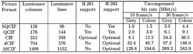
[image:13.612.333.540.197.270.2]Again, the H.263 codec was detailed in [27], [53], and [175], while a number of transmission schemes designed for accommodating its rather error-sensitive bit stream were proposed, e.g., by the prestigious video communications groups led by Girod at Stanford University, Kondoz at Surrey University, Bull at Bristol University, and others, e.g., in [130]–[147]. As an illustrative example, in Table 5, we summarized the various video resolutions supported by the H.261 and H.263 ITU codecs in order to demonstrate their flexibility [27]. Their uncompressed bit rates at frame scanning rates of both 10 and 30 frames/s and for both gray
Table 6
Video Sequences Used for H.263 Simulations
and color video are also listed. The mature H.261 standard defined two different picture resolutions, namely, the 144 176 pixel QCIF and the 288 352 pixel CIF, while the H.263 codec has the ability to support five different res-olutions. All H.263 decoders must be able to operate in sub-QCIF (SQCIF) and QCIF modes and optionally support CIF, 4 CIF, and 16 CIF formats. We note, however, that for cellular and cordless systems, only the 96 128 pixel SQCIF and the QCIF resolutions are realistic in terms of their minimum required bit rates. Hence, in this contribution, we will concentrate mainly on using QCIF sequences.
C. H.263 Codec Performance
In this section, we will report our findings with regards to the tradeoffs between image quality and bit rate for dif-ferent image sizes, frame rates, and video sequences when using the H.263 codec, in order to demonstrate its ability to support the operation of intelligent multimode transceivers. All simulations were conducted using well-known video se-quences at both 10 and 30 frames/s. The video sese-quences used are summarized in Table 6. The image resolutions em-ployed were described in Table 5. Due to the bit-rate limita-tions imposed by cellular and cordless systems, here we will mainly concentrate our discussions on the smaller SQCIF and CIF formats and refer the interested reader to [26], [146], and [147] for further results concerned with high-resolution, high-rate WATM-type systems using an OFDM modem and binary BCH as well as turbo channel codecs.
Fig. 5. Image quality (PSNR) versus compression ratio performance of the H.263 codec for the QCIF “Miss America” sequence in color and grayscale at 10 and 30 frames/s.
quality expressed in terms of peak signal-to-noise ratio (PSNR)4 versus bit rate and compression ratio, respectively.
These graphs suggest that the grayscale and color PSNR performances are rather similar, but their difference becomes slightly more dominant with increasing bit rate. These ten-dencies imply that assuming a constant bit rate, only a small fraction of the overall bit rate has to be allocated to convey the color information, and, therefore, the PSNR penalty due to reducing the bit rate and resolution of the luminance component, required to accommodate the color information is marginal.
2) Comparison of QCIF Resolution Color Video: The in-vestigations in this section were conducted in order to char-acterize the performance of the H.263 codec for a range of different video sequences. All simulations were carried out using color video sequences scanned at 10 and 30 frames/s. The video sequences used were “Miss America,” “Suzie,” and “Carphone.” Some example QCIF video sequences can also be viewed on the Web.5
The results of these simulation-based experiments are plotted in Fig. 6. As expected on the basis of its low mo-tion activity, the graphs suggest that the “Miss America” sequence is the most amenable to compression, followed by “Suzie,” and then the “Carphone” sequence. The achievable compression ratios span an approximately one order of magnitude range when comparing the lowest and highest activity sequences. Due to lack of space here, we have to curtail our elaborations on the rather instructive further aspects of the H.263 scheme using, for example, different resolution sequences. A range of further bit-error sensitivity and transmission aspects at various resolutions are detailed in [27], while for further results concerned with high-res-olution, high-rate WATM-type systems using an OFDM
4The PSNR is an often used video quality measure, which is similar to
the conventional SNR, with the exception that the video reproduction error energy due to the coding impairments is normalized not to the actual signal energy but to the energy of a hypothetical video frame, where all pixels have the luminance value of 255.
5http://www-mobile.ecs.soton.ac.uk/peter/h263/h263.html#Examples.
[image:14.612.308.526.27.193.2]Fig. 6. Image quality (PSNR) versus compression ratio performance of the H.263 codec for QCIF resolution at 10 and 30 video frames/s.
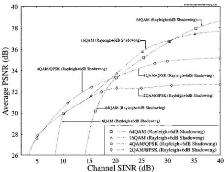
Fig. 7. Decoded video PSNR versus channel SNR performance for transmissions over Rayleigh-fading channels with 6-DB shadow fading using BPSK, QPSK, 16 QAM, and 64 QAM (from [142]).
modem and binary BCH as well as turbo channel codecs, the interested reader is referred to [27], [146], and [147].
VI. VIDEOPERFORMANCEWITHOUTPOWERCONTROL
In this section, we characterize the expected video system performance of the prototype scheme employed, when using no power control, a scenario often encountered in the cord-less telephone schemes of Table 1, i.e., in DECT, CT2, etc.
The PSNR versus average SINR performance of the var-ious transceiver modes is portrayed in Fig. 7 in conjunction with shadow fading exhibiting a standard deviation of 6 dB. In systems, where the erroneously channel decoded trans-mission bursts are discarded in an effort to prevent channel error propagation to future video frames through the recon-structed video frame buffer due to the motion-compensation assisted interframe coding, the transmission burst error rate (BurstER) was found to be a reliable parameter in controlling the modem modes [27]. It was found advantageous to invoke a more robust modem mode typically around BurstER
[image:14.612.42.270.28.200.2] [image:14.612.304.532.245.420.2]a less robust mode due to channel errors dropped below that of the next more robust mode exhibiting an inherently lower, but unimpaired, PSNR. In other words, this implied that a lower PSNR—which was unimpaired however by channel effects—was typically preferable to an originally higher, but channel-impaired, scenario. The associated subjective effects are characterized by the corresponding video demonstrations that can be viewed on the web.6
In order to avoid a set of repetitive illustrations, the asso-ciated modem mode-switching dynamics will be exposed in more detail at a later stage, in the context of Figs. 14–17 in conjunction with our burst-by-burst adaptive CDMA system of Section IX.
In contrast to the H.261 codec, where it was legitimate to refrain from encoding specific macroblocks constituted by four 8 8-pixel video blocks, in the H.263 scheme every MB has to be transmitted. However, inactive macroblocks can be coded using a 1-bit codeword. Due to the packet drop request upon corruption now the MBs are reencoded as empty MBs, conveying no information, i.e., assuming that they contain zero-valued motion-compensated error residual pixels. This is equivalent to assuming that the video content of the current video block has not changed since the reception of the pre-vious video frame. In such events, both the local and remote decoders have to be informed that the partially received MB has to be removed from their buffers. Hence, some parts of the picture cannot be updated during the video frame con-cerned. However, in most cases the dropped MBs will be updated in the next video frame. The effect of video packet dropping is not noticeable unless the video frame contains a large amount of motion and the packet dropping probability is very high. Again, these subjective effects can be viewed at various video packet dropping rates by displaying the de-coded video sequences available on the Web.7 The
corre-sponding objective PSNR degradation versus packet drop-ping rate is characterized by Fig. 8, indicating that as long as this dropping rate remains below about 5%, the video degradation remains unobjectionable. Hence, we designed an error-rate-based power-control scheme with the specification of maintaining the required transmission packet dropping or—synonymously—transmission burst error rate, which is characterized briefly in the next section. For a full flowchart and implementational details, the interested reader is referred to [27] and [145].
VII. VIDEOPERFORMANCEUSINGPOWERCONTROL
In this section, we highlight the expected video system performance of the prototype design with power control, which is typically the situation in the cellular, rather than cordless, systems of Table 1, i.e., in systems, such as GSM, IS-54, IS-95, UMTS, etc.
Important contributions in the field of power control are due, e.g., to Zander [176], [177], Zorzi [178], Leung [179], Ariyavisitakul et al. [180], Pichna and Wang [181], and Lee
6http://www-mobile.ecs.soton.ac.uk/peter/robust-h263/robust.html. 7http://www-mobile.ecs.soton.ac.uk/peter/robust-h263/robust.html
[image:15.612.321.550.27.200.2]#DROPPING.
Fig. 8. Average PSNR of decoded video versus video packet dropping rate—or synonymously—transmission BurstER, for 2, 4, 16, and 64 QAM over both Gaussian and Rayleigh-fading channels. The QCIF resolution “Miss America” video sequence was used for all transmission modes (from [142]).
et al. [182]. A power-control algorithm needs an accurate and recent estimate of the radio channel’s quality. The systems that rely on the received signal strength indicator (RSSI) to measure channel quality have to tolerate that the accuracy of the channel estimation is reduced in an interference-lim-ited environment. Various techniques to reduce this inaccu-racy have been suggested, in particular an averaging tech-nique by Austin and Stüber [183]. Error-rate-based power-control schemes give a reliable channel quality estimation but have some limitations. An attractive power control algorithm based on a combination of BER and RSSI estimates was pro-posed by Chuang and Sollenberger [184]. Also Kumar et al. [185] proposed a power-control algorithm based on BER measurements.
In our proposed BER-based power-control algorithm, the main channel quality indicator was the transmission burst error flag (BEF), which we defined as a 1-bit Boolean flag, where a logical one indicated that a transmission burst was error-free while a zero signaled an erroneous transmission burst reception. In order for the transmitter to infer, whether a transmission burst was received correctly, a binary acknowl-edgment flag was sent from the receiver, which is associated with a delayed indication of the channel quality. This delay was explicitly quantified in Fig. 4. If this delay is too high, the transmission burst error flag may be of little use. This delay is one of the disadvantages of BER-based techniques in com-parison to systems that use an RSSI reading carried out by the receiver in order to set the transmission power. However, the RSSI-based systems are easily deceived by high levels of co-channel interference.
Table 7
Power Control Algorithm’s Features
higher than the correcting capability of the FEC code, then a transmission frame error has occurred, and increasing the transmission power should be of urgent consideration. How-ever, if the number of errors contained in the BCH-coded transmission burst is correctable by the FEC, there are three possible situations that should be considered. First, if the number of errors is near to the error correction capability of the code, where a transmission burst error would occur, or the number of errors in successive transmission bursts has been increasing, then the transmission power should be increased. Secondly, if the number of errors in the transmission burst is low and has been reduced in previous transmission bursts, then the power should be reduced. Lastly, when the transmission burst is not error-free but the errors are correctable by the FEC, it is logical to keep the transmission power constant. For further intrinsic details of the power-control algorithm, interested readers are referred to [27] and [145]. The amount of time to delay an action before the power-control algorithm increases or decreases the power depends on many factors, such as the modulation scheme employed, the channel conditions, the required transmission BurstER, etc. The power-control algorithm proposed in this contribution exhibits a variable step size and has been tested with a power control delay of one TDMA frame. An advantage of this regime is that it can support the modem’s operation, irrespective of the modem mode employed. Based on the above rationale, the power-control algorithm’s main features are shown in Table 7. We used a typical maximum transmission power of 1 W with a dynamic range of 64 dB as in GSM.
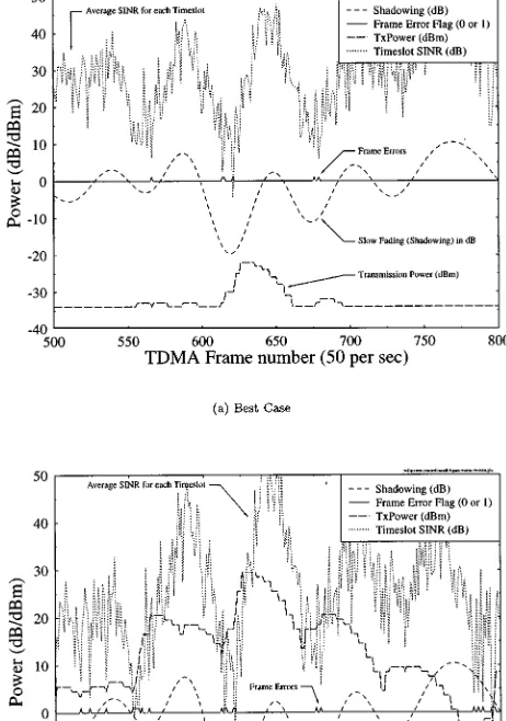
[image:16.612.75.233.53.119.2]The performance of the power-control algorithm was tested in the worst case scenario of a single interfer used to inflict co-channel interference. Examples are shown in Fig. 9(a) and (b) for the best and worst case situations using 4 QAM, where the best case is when the interferer is far from the serving BS and the user is close to its corre-sponding BS, and vice versa. Specifically, Fig. 9(a) shows the transmission power variation versus time, demonstrating that the transceiver is operating close to the minimum of 34 dBm. Both of the subfigures display the slow fading, the SINR average over each time slot, the transmission burst error flag, and the transmission power. The worst case situation seen in Fig. 9(b) shows more clearly how the power control reacts to the fluctuating SINR. Observe in Fig. 9 that the transmission burst error flag suggests a moderate FEC overloading event frequency, irrespective of the path loss and slow fading experienced. Furthermore, it can also be seen that the transmission power is limited to the maximum power of 30 dBm at one point.
Fig. 9. Various waveforms associated with the error rate based power control algorithm. (a) Best case situation is when both the interfer and the user are close to their BS. (b) Worst case situation is when both the interferer and the user are at the edge of their cell (from [144] and [145]).
As expected, the power-control algorithm maintains a near-constant BCH-coded transmission burst error rate across the whole cell area, which is demonstrated by Fig. 10. The target BurstER was adjusted to around 5%, as required by the video transceiver, in order to maintain the target PSNR, but in the extreme vicinity of the BS the power could
not be reduced below the dBm level, which
Fig. 10. Transmission BurstER with power control versus user and interferer distance from BS using 4 QAM (from [144] and [145].
keying (BPSK) to 4-QAM mode there is a slight power increase, in order to avoid the received power range near the modem mode switching thresholds. This is because without powering up, when switching from BPSK to 4 QAM the receiver would experience the lowest possible channel SNR associated with the 4-QAM mode instead of the highest possible SNR of the BPSK mode, potentially resulting in a BurstER higher than that at the top of the BPSK SNR range. Having characterized the system architecture and the achievable performance of the TDMA/TDD-based mul-timode system used in our design example, let us now demonstrate in the next section how these attractive system design features can be extended to CDMA systems, which were proposed for the 3G wireless arrangements worldwide.
VIII. BURST-BY-BURSTADAPTIVEJOINT-DETECTION CDMA VIDEOTRANSCEIVER
A. Multiuser Detection for CDMA
The effects of multiuser interference (MAI) are similar to those of the ISI inflicted by the multipath propagation channel. More specifically, each user in a -user system will suffer from MAI due to the other users. This MAI can also be viewed as a single user’s signal contaminated by the ISI due to propagation paths in a multipath channel. Therefore, conventional equalization techniques used to mitigate the effects of ISI can be modified for employ-ment in multiuser detection assisted CDMA systems. The so-called joint detection (JD) receivers constitute a category of multiuser detectors developed for synchronous burst-based CDMA transmissions, and they utilize these techniques.
Fig. 11 depicts the block diagram of a synchronous joint-detection assisted CDMA system model for uplink transmis-sions. There are a total of users in the system where the information is transmitted in bursts. Each user transmits data symbols per burst, and the data vector for user is rep-resented as . Each data symbol is spread with a user-spe-cific spreading sequence , which has a length of chips. In the uplink, the signal of each user passes through a dif-ferent mobile channel characterized by its time-varying com-plex impulse response . By sampling at the chip rate of , the impulse response can be represented by com-plex samples. Following the approach of Klein et al. [57], the received burst can be represented as , where is the received vector and consists of the synchronous sum of the transmitted signals of all the users, corrupted by a noise sequence . The matrix is referred to as the system matrix and defines the system’s response, representing the effects of MAI and the mobile channels. Each column in the matrix represents the combined impulse response ob-tained by convolving the spreading sequence of a user with
its channel impulse response . This is the
impulse response experienced by a transmitted data symbol. Upon neglecting the effects of the noise, the JD formulation is simply based on inverting the system matrix in order to recover the data vector constituted by the superimposed transmitted information of all the CDMA users.
B. JD-ACDMA Modem Mode Adaptation and Signaling
![Table 2UTRA/IMT-2000 System Parameters (From [68])](https://thumb-us.123doks.com/thumbv2/123dok_us/1040817.619665/3.612.322.550.54.253/table-utra-imt-system-parameters-from.webp)
![Fig. 1.Simulated normalized channel capacity profile of a hexagonal cell without power control,employing a reuse factor of seven—corresponding to six first-tier interferers—a path loss exponentof 3.5, slow-fading frequency of 1 Hz, standard deviation of 6 dB, and six stationary 4-QAM uplinkvideo interferers at random positions within cell boundaries (from [142]).](https://thumb-us.123doks.com/thumbv2/123dok_us/1040817.619665/5.612.146.464.29.312/simulated-normalized-corresponding-interferers-exponentof-uplinkvideo-interferers-boundaries.webp)
![Table 4Summary of System Features for the Reconfigurable Mobile Radio System (From [142])](https://thumb-us.123doks.com/thumbv2/123dok_us/1040817.619665/6.612.79.493.78.342/table-summary-features-reconfigurable-mobile-radio.webp)
![Fig. 3.Simulated average SIR (dB) profile of a hexagonal cellwithout power control, employing a reuse factor of seven, path lossexponent of 3.5, slow-fading frequency of 1 Hz, standard deviationof 6 dB, 4-QAM modulation, and interference from six stationaryvideo users in co-channel cells (from [142]).](https://thumb-us.123doks.com/thumbv2/123dok_us/1040817.619665/7.612.328.550.24.183/simulated-cellwithout-employing-lossexponent-deviationof-modulation-interference-stationaryvideo.webp)
![Fig. 8.Average PSNR of decoded video versus video packetdropping rate—or synonymously—transmission BurstER, for 2, 4,16, and 64 QAM over both Gaussian and Rayleigh-fading channels.The QCIF resolution “Miss America” video sequence was used forall transmission modes (from [142]).](https://thumb-us.123doks.com/thumbv2/123dok_us/1040817.619665/15.612.321.550.27.200/packetdropping-synonymously-transmission-gaussian-rayleigh-resolution-america-transmission.webp)