Abstract—The demands for traffic and services through the
mobile networks are ever increasing. Multi-tier has become a major trend in the design of new generations of mobile networks such as advanced long term evolution ( LTE-A) networks in order to support the high capacity demand required for multiservice traffic in wireless networks. Picocell emerged as one of the key radio access techniques for LTE-A networks to increase the LTE-Advanced coverage and capacity requirements in a cost-efficient way. Two-tier networks, comprising a LTE Macro- cellular network overlaid with shorter range and low power Picocells offer an economically important approach to improve the LTE-A network capacity. In this type of network an efficient call admission control scheme is required to improve the connection level Quality of Service (QoS) of the wireless networks in terms of dropping probability, blocking probability and resources utilization. This paper proposes a two-tier call admission control scheme for integrated LTE-A/Picocells to efficiently utilized the available resources and improve the network coverage. We compare and evaluate the proposed CAC in single and two-tier LTE-A networks. The results shows that using two-tier CAC with Picocell resource sharing increases the performance of the system in term of high utilization and blocking probability reductions.
Index Terms— LTE-Advanced; Admission Control;
Resource allocation; Pico-cell
I. INTRODUCTION
HE Long Term Evaluation (LTE) standard has been published in March of 2009 in the first version as part of the Third Generation Partnership Project (3GPP) Release 8 specifications. LTE did not improve system spectral efficiency, but it improves system performance by using wider bandwidths if the spectrum is available. The 3GPP has explained that call admission control is to make a decision of accepting a new radio request [1]. The 3GPP has been working on various aspects to improve the performance of LTE in the framework of LTE Advanced (LTE-A) which include Orthogonal Frequency Division Multiple Access (OFDMA), higher order multiple inputs multiple output MIMO, carrier aggregation (multiple component carriers), and heterogeneous networks (relays, picocells and femtocells) [2] [3].
The traditional approach to increase the capacity of the
Manuscript received June 29, 2015; revised July 29, 2015.
Salman A. AlQahtani is with the Computer Eng. Dept., King Saud University, Riyadh, Saudi Arabia (00966505225172; e-mail: salmanq@ ksu.edu.sa).
Nasser M. Ahmed Author is with the Computer Engineering Department, King Saud University, Riyadh, Saudi Arabia (e-mail: [email protected]).
communications network is to add more macrocells with high coverage area and high data rate in the hotspot areas in the network where there is a big intensity of data traffic. This approach has a disadvantage of high cost implementation and due to the rapid growing demand for data services, it is increasingly difficult to support the required data capacity through that traditional approach which requires deployment of additional macro eNodeBs (MeNBs). However the alternative new approach that proposed in LTE-A project is the placement of smaller cells with smaller coverage and a lower implementation cost within the macro cell coverage areas these small cells called Picocells [4] [5] [6]. This new approach is the basic concept of Heterogeneous Networks which have been included in the LTE-A system by 3GPP to improve the overall system throughput and capacity [7].
Two-tier networks, comprising a LTE Macro- cellular network overlaid with shorter range and low power Picocells offer an economically important approach to improve the LTE-A network capacity. In order to achieve the advantages of this type of integrated network, an efficient call admission control scheme is required to improve the connection level Quality of Service (QoS) of the wireless networks in terms of dropping probability, blocking probability and resources utilization. This paper proposes a two-tier call admission control scheme for integrated LTE-A/Picocells to efficiently utilized the available resources and improve the network coverage.
The rest of this paper is organized as follows. The related works and research contributions are presented in Section II. In Section III, the proposed CAC schemes are provided and explained. In section IV, we offer a brief overview of the system model. In Section V, we present the simulation environment together with the parameters used and the metrics chosen as the basis for evaluation. Then we analyze the results obtained. Finally, we conclude in Section VI.
II. RELATED WORKS AND RESEARCH CONTRIBUTIONS
Many researches have been done in related to CAC in LTE-A [3-8]. In [5] an alternative deployment models or topologies using heterogeneous networks to enhance the performance of these networks are presented. In [6], a quality based call admission control and resource allocation mechanism are provided to avoid resource overloading and call quality degradation. In [8] the researcher focused in addressing the problem of the inter-cell interference between Macrocell and Picocell to improve the system capacity. In [9], the authors studied the effect of Picocell deployment to
Call Admission Control for Two-Tier LTE
Macro/Pico Cellular Networks
Salman A. AlQahtani and Nasser M. Ahmed
the system capacity; they found out that the deployment of picocells at the cell edge is more beneficial than in the cell center. In [10], the author proposed a deployment scheme of Picocell on Macrocell, he found out that the deployment of picocells in the hotspot areas where there is high intensity of traffics make more enhancement in system performance more than radio access features such as cell range expansions (CRE). In [11], the performance of combined admission control and packet scheduling for QoS support and service differentiation is presented.
The issues of CAC in LTE-A relay system which is based on resource sharing is presented in [12]. A wireless backhaul channel shared among Picocells is provided in [13]. A backhaul scheduling approach based on traffic demands on Picocells that maximizes the Picocell utility is proposed and evaluated. In [14] the author has proposed and analyzed a new resource allocation control framework called a preemption-based call admission control scheme (PCAC) for integrating independent underlying Picocell with Macrocell networks, he aimed to utilize the resource blocks (RBs) of picocells (owned by multi-operators) efficiently to improve Macro-cell user (MU) performance by allowing its MU visitors to utilize unused Picocell RBs without any degradation for Picocell users. He found out that the system throughput is improved using the proposed CAC. For LTE-A integrated with Picocells in two tiers networks, the resource management should be designed in an efficient way to maximize the utilization of radio resources and also to increase the system throughput and reduce the blocking probability.
The main contribution of this paper is to address this issue. An efficient Call Admission Control (CAC) in the two- tiers LTE- Pico networks in is proposed to efficiently utilized the available resources and improve the network coverage. We compare and evaluate two strategies for the CAC in single and two-tier LTE-A networks. In single tier, LTE and Picocell has its own users and its own resources while in two-tier the available resources of Picocell can be shared by LTE users and Pico user. By using a developed simulation program, two strategies is presented and compared.
III. CALL ADMISSION CONTROL SCHEMES
A. System Model and Assumptions
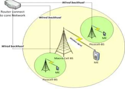
We consider a single cell uplink LTE-A network integrated with number of Picocells as shown in Fig. 1. It is assumed that the LTE-A Macrocell overlays a number of picocells. In this single cell, there are number of mobile networks users (MNs) equipped by dual interface to provide the users with the ability to connect to both Picocell and LTE-A cells. Only a single Picocell is considered, and MNs prefer to connect to that Picocell as long as they are in its range. Therefore, the Picocell is open to all MNs within its coverage when it has unused resources in addition to its local users. The coverage area of Picocell is small comparing to LTE-A cell and we supposed that the coverage area of
[image:2.595.305.551.79.253.2]Picocell is overlapped and existing within LTE coverage area. The users are uniformly distributed in the cell.
Fig. 1: The architecture of LTE-A networks with Picocell
We assumed that the coverage area of Picocell can be denoted as and the coverage area of LTE can be denoted as . The channel capacity for Picocell and LTE can be represented as and , respectively. The new arrival MN is generated randomly within the total coverage area of LTE and Picocell in different position distributed uniformly, and the arrival of MN's will be modeled as a Poisson distribution. When a new LTE-A MN arrives (a new call arrives), it could be within the coverage of a Picocell with a probability of , and it is sure that is with LTE coverage area since Picocell within LTE coverage area, or it could be outside Picocell coverage area and within LTE coverage area only with a probability (1-p). We assume that the system uses the frequency-division duplex (FDD) mode, where the uplink and downlink are each allocated BW (MHz) transmission bandwidth. In addition, we assume that each radio frame contains a set N of RBs for data transmission. The value of N depends on the bandwidth W selected. The system resources are defined in terms of LTE-A RBs. Each request type has a specific number of RBs to use, and the RBs assignment is decided by the resource allocation scheme in used. We assume that each MN needs one RB. The new arrival of LTE user or Pico user is assumed to follow Poisson arrival process with mean rates of and respectively. They have a negative exponential service time distribution with mean rates of and respectively. We also supposed that the system has a buffer with a limit size equal to M and N users for LTE and Pico respectively, and the arrival MN can still inside the buffer waiting an exponential time for service, this waiting time equals to seconds for LTE and Picocell respectively.
B. Call Admission control Strategies
available resources of Picocell can be shared by LTE users and Pico user. These two schemes are explained as follows: 1) CAC in single tier network (Basic Scheme):
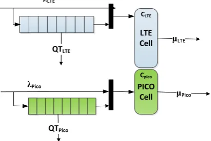
In this Scheme there is no cooperation between LTE and Picocell where the Picocell has its own users and resources and LTE also has its own users and resources. This scheme model is shown in the Fig. 2. The admission control scheme of the new arriving connection requests first estimates the total available bandwidth by computing the free cells RBs (which are not occupied) and estimate the required resources blocks RBs (new load increment) for the new request and uses these information in decision making of accepting or rejecting new connection requests. Assume we have k request and each request need n resource blocks RBs, then the
residual resources will be ;
where is the residual resources, and is the total number of resource block in the system.
In this Scheme, the total capacity of LTE is N of RBs, and the total capacity of Picocell is C of RBs. The MNs that arrives in to a Picocell with arrival rate will be connected to Picocell only if there are available resources within the Picocell. The MNs that associated and the new arrival to LTE-A with arrival rate will be admitted to LTE only if there is available bandwidth in LTE. If there is no available resource, then the new arrival will be inserted into the system queue to wait for the service if there is an empty room in the queue otherwise it will be dropped. Then the MN will wait for the service an exponential time with mean equal to seconds for LTE and Picocell respectively. If this waiting time exceeded, the MN will be dropped.
LTE Cell
PICO Cell QTLTE
QTPico
µLTE
µPico λLTE
λPico
CLTE
[image:3.595.326.529.207.353.2]Cpico
Fig. 2: System model for the Basic Scheme.
2) The Proposed CAC Scheme for two tier network:
In this Scheme, there is cooperation from Picocell side. This scheme model is shown in the Fig. 3 and it has the pseudo code shown in Table I. In this scheme, the new arrival of Picocell will be connected to Picocell if there is an available bandwidth and if there is no enough resources it will be inserted into Picocell queue if there is a vacant room in Picocell queue. Then a Picocell user wait in the queue an exponential time with mean value equal to seconds, if this waiting time is exceeded then the Picocell user will be dropped. If there is no vacant room in Picocell queue, then the new arrival will be dropped. The arrival associated to
LTE, will be connected to LTE if there is enough resources. If there are no enough resources in LTE-A then the probability value of is calculated. If LTE arrived MN is within the coverage of a Picocell and there is an available resource in Picocell, It will be connected to the Picocell. Otherwise, LTE user will be queued in LTE-A queue if there is empty room and the MN will wait for an exponential time with mean value equal to seconds. If this time IS exceeded then LTE user will be dropped. If there is no vacant room in LTE Queue, then LTE user will be blocked.
LTE Cell
PICO Cell QTLTE
QTPico
µLTE
µPico λLTE
λPico
CLTE
[image:3.595.306.537.400.618.2]Cpico p
Fig .3 System model for the Proposed Scheme TABLEI
THE PROPOSED CACALGORITHM FOR TWO TIER NETWORK
For each
If Pico_BW > the requested MN_BW Then connect Pico_MN to Pico Else
CheckQ (Pico) End
For each :
If LTE_BW > the requested MN_BW Then connect MN to LTE
Else; Check if LTE_MN within the pico coverage If LTE_MN within the Pico cell coverage then if Pico_BW > the requested MN_BW Connect LTE_MN to Pico Else CheckQ (LTE) Else CheckQ (LTE) End
CheckQ (A)
If A queue is not full Insert A_MN to A Queue Else
A_MN is Blocked
End
IV. SIMULATION RESULTS AND DISCUSSIONS
[image:3.595.305.540.400.619.2] [image:3.595.67.273.469.607.2]TABLEII
SIMULATIONPARAMETERSFORTHENETWORKS Parameter Value Radio Access Mode OFDMA
Uplink channel bandwidth 10 MHz RBs 50 (500 per frame) Heights MCS 64-QAM, R=9/10
Antenna Single Antenna (Tx=1, Rx=1) (SISO Service duration Exponential (100 sec)
A. Performance Metrics
The system performance metrics that are used to evaluate the proposed scheme are the total loss probabilities (PL) and the system utilization (U). These performance measures can be defined as follows. Total loss probability is a measure of the QoS of service offered by the resource allocation scheme. The total loss probability of a type T is the blocking probability ( ) in addition to the time out probability of the unblocked requests of the same type ( ). ( ) is defined as the fraction of new connection requests of type T that are blocked because of the lack of space in its queue. ( ) is defined as the fraction of queued connection requests of type T that are dropped because the queuing time limit is exceeded. can be written as follows. As it define in [9]
; where T is the type of user LTE or Pico
The system utilization can be defined as the average of the number of allocated RBs, number of resources block used in the cell of interest during the system operations over the maximum cell capacity load. This term measures the system RBs efficiency, which is the proportion of the time wherein RBs are available and used to the total time of simulation (expressed usually as a percentage) [9].
B. Results Discussion
In this part, the probability of loss and utilization using two schemes (Basic Scheme and Proposed Scheme) will be investigated. The simulation has run according the parameter mentioned in previous section. The main findings are explained as follows.
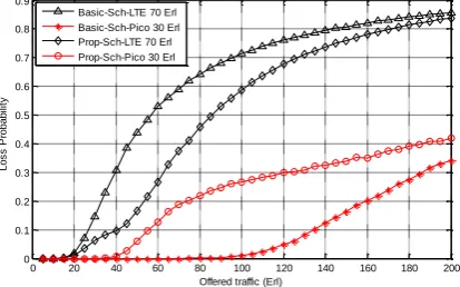
Fig.4 shows the probability of loss using two schemes in which the X-axis represents the offered traffics, and Y-axis represents the probability of loss. The LTE offered traffic constitutes 70% of the total traffics and Pico offered traffic constitutes 30% of the total traffics. It is clear that the loss probability of LTE users in the proposed Scheme (black color line with -ــ◊ــ ) is reduced comparing it to its value in the basic scheme (Black color with ــ ). This is because the ∆ــ LTE users that cannot get a connection to LTE sub-system can be served in Picocell. In the other hand the loss probability in Picocell system increases because the Picocell system will serve part of LTE users.
0 20 40 60 80 100 120 140 160 180 200
0 0.1 0.2 0.3 0.4 0.5 0.6 0.7 0.8 0.9
Offered traffic (Erl)
L
o
s
s
P
ro
b
a
b
ili
ty
Basic-Sch-LTE 70 Erl Basic-Sch-Pico 30 Erl Prop-Sch-LTE 70 Erl Prop-Sch-Pico 30 Erl
Fig. 4. Loss Probability for the both Schemes (Proposed & basic)
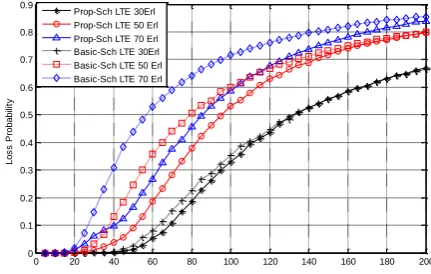
Fig. 5 displays the loss of probability of LTE sub-system with different offered traffic where the traffic of LTE constitutes 30%, 50%, and 70% of the total traffics. X-axis represents offered traffic and Y-axis represents the Loss of probability. When LTE is 30% of the total offered traffic (black colored curves with ـــ*ـــ and with --+-- for proposed and basic schemes respectively ( , the Loss of probability of LTE in both scheme is approximately similar and there is small improvement in Loss of probability of the proposed Scheme. This is due to the light traffic load of LTE, where the LTE sub-system has the ability to serve most of their traffic without needing to cooperate with the Pico system. The two red curves (with ـــoـــ and with --□-- for proposed and basic schemes respectively) compare the probability of Loss of LTE when the traffic of LTE constitutes 50 % of the total traffics. It is clear that there is a noticeable improvement in the probability of loss because that some of LTE users that cannot be served by LTE can be served by Pico sub-system. The improvement in probability of loss of LTE in the proposed scheme will be clear as the LTE traffics become very high as displayed by the two blue curves (with
ـــ ∆
ـــ and with ---◊--- for proposed and basic schemes respectively) that compare the probability of Loss of LTE in the both two scheme when the LTE traffics constitutes 70% of the total traffics.
[image:4.595.322.529.61.190.2]0 20 40 60 80 100 120 140 160 180 200 0
0.1 0.2 0.3 0.4 0.5 0.6 0.7 0.8 0.9
Offered traffic (Erl)
L
o
s
s
P
ro
b
a
b
ili
ty
[image:5.595.61.277.59.196.2]Prop-Sch LTE 30Erl Prop-Sch LTE 50 Erl Prop-Sch LTE 70 Erl Basic-Sch LTE 30Erl Basic-Sch LTE 50 Erl Basic-Sch LTE 70 Erl
Fig.5. Loss of probability of LTE with different OT
20 30 40 50 60 70 80 90 100 110
0.5 0.55 0.6 0.65 0.7 0.75 0.8 0.85 0.9 0.95 1
Offered traffic (Erl)
U
ti
liz
a
ti
o
n
Total UTILISATION DIAGRAM for Schem 2 in different OT
[image:5.595.60.270.222.359.2]Prop-Sch 30 LTE:70 Pico Prop-Sch 50 LTE:50 Pico Prop-Sch 70 LTE:30 Pico Basic-Sch30 LTE:70 Pico Basic-Sch 50 LTE:50 Pico Basic-Sch70 LTE:30 LTE
Fig. 6. Total Utilization of LTE system with different OT
It shows that there is a noticeable utilization improvement using the proposed scheme. The two black curves (with ـــ*ـــ and --+-- for the proposed and basic scheme respectively) in Fig. 6 shows the total utilization of the system when LTE traffics constitutes 30% and Pico traffics constitutes 70% of the total traffic load. It is clear that there is no improvements in utilization and the results of utilization in both schemes are the same since the traffics load of pico system is very high and the proposed scheme works as the basic scheme. In Fig. 7 It is also displayed that both schemes have the same performance when both system have a heavy load because the utilization reaches to its maximum value and all RBs are utilized in each system. In the case of light traffic load (less than 30 Erl.), the utilization of the system in both schemes are similar because there is no need to make cooperation between the two sub-systems and each subsystem is capable of serving their users.
0 20 40 60 80 100 120 140 160 180 200
0 0.1 0.2 0.3 0.4 0.5 0.6 0.7 0.8 0.9 1
Offered traffic (Erl)
U
ti
liz
a
ti
o
n
Total UTILISATION DIAGRAM for Schem 2 in different OT
[image:5.595.64.272.613.750.2]Prop-Sch 30 LTE:70 Pico Prop-Sch 50 LTE:50 Pico Prop-Sch 70 LTE:30 Pico Basic-Sch30 LTE:70 Pico Basic-Sch 50 LTE:50 Pico Basic-Sch70 LTE:30 LTE
Fig 7. Total Utilization of LTE system with different OT
V. CONCLUSION
We proposed a two-tier call admission control scheme for integrated LTE-A/Picocells to efficiently utilized the available resources and improve the network coverage. We compared and evaluate the proposed CAC in single and two-tier LTE-A networks. The results shows that using two-two-tier CAC with Picocell resource sharing increases the performance of the system in term of high utilization and blocking probability reductions. The results also proved that the proposed CAC the utilization of the system has been improved and the Loss probability of the system has been reduced especially at low to medium traffic.
REFERENCES
[1] P. Serra and A. Rodrigues, "Picocell positioning in an LTE network." [2] P. Tian, H. Tian, L. Gao, J. Wang, X. She, and L. Chen, "Deployment
analysis and optimization of macro-Pico heterogeneous networks in LTE-A system," in Wireless Personal Multimedia Communications (WPMC), 2012 15th International Symposium on, 2012, pp. 246-250. [3] S. A. AlQahtani, "Analysis of an Adaptive Priority Based Resource
Allocation Control for LTE-Advanced Communications with Type I Relay Nodes," Wireless Personal Communications, vol. 77, pp. 2699-2722, 2014.
[4] F. Liu, X. She, L. Chen, and H. Otsuka, "Improved Recursive Maximum Expansion Scheduling Algorithms for Uplink Single Carrier FDMA System," in Vehicular Technology Conference (VTC 2010-Spring), 2010 IEEE 71st, 2010, pp. 1-5.
[5] A. Khandekar, N. Bhushan, T. Ji, and V. Vanghi, "LTE-Advanced: Heterogeneous networks," in Wireless Conference (EW), 2010 European, 2010, pp. 978-982.
[6] C. Olariu, J. Fitzpatrick, P. Perry, and L. Murphy, "A QoS based call admission control and resource allocation mechanism for LTE femtocell deployment," in Consumer Communications and Networking Conference (CCNC), 2012 IEEE, 2012, pp. 884-888.
[7] T. Peng, T. Hui, G. Liqi, W. Jing, S. Xiaoming, and C. Lan, "Deployment analysis and optimization of Macro-Pico heterogeneous networks in LTE-A system," in Wireless Personal Multimedia Communications (WPMC), 2012 15th International Symposium on, 2012, pp. 246-250.
[8] M. Eguizabal and A. Hernandez, "Interference management and cell range expansion analysis for LTE picocell deployments," in Personal Indoor and Mobile Radio Communications (PIMRC), 2013 IEEE 24th International Symposium on, 2013, pp. 1592-1597.
[9] S. Landström, H. Murai, and A. Simonsson, "Deployment aspects of LTE pico nodes," in Communications Workshops (ICC), 2011 IEEE International Conference on, 2011, pp. 1-5.
[10] A. Daeinabi, K. Sandrasegaran, and X. Zhu, "Performance evaluation of cell selection techniques for picocells in LTE-advanced networks," in Electrical Engineering/Electronics, Computer, Telecommunications and Information Technology (ECTI-CON), 2013 10th International Conference on, 2013, pp. 1-6.
[11] M. Anas, C. Rosa, F. D. Calabrese, K. I. Pedersen, and P. E. Mogensen, "Combined Admission Control and Scheduling for QoS Differentiation in LTE Uplink," in Vehicular Technology Conference, 2008. VTC 2008-Fall. IEEE 68th, 2008, pp. 1-5.
[12] H. Han and J. Zhao, "Call admission control based on resource sharing in LTE-Advanced relay system," in Advanced Communication Technology (ICACT), 2014 16th International Conference on, 2014, pp. 1071-1076.
[13] Maric, x, I., Bos, x030C, tjanc, x030C, ic, x030C, B., and A. Goldsmith, "Resource allocation for constrained backhaul in picocell networks," in Information Theory and Applications Workshop (ITA), 2011, 2011, pp. 1-6.