DESIGN AND IMPLEMENTATION OF SIMPLE METAL DETECTOR
PhyuPhyu Mar
Department of Engineering Physics, Yangon Technological
ARTICLE INFO ABSTRACT
The simplest form of a metal detector was included an oscillator which
current and magnetic field that passes through a coil. When a piece of electrically conductive metal is closed to the coil, eddy currents will be induced in the metal, to form create its own mag
a metal detector
It is short range device and between 9 inch and below, it can detect any metal between this range such as gold, tin, steel and any electropositive elements.
Copyright©2019, Phyu Phyu Mar and Aye Thida Aung.
unrestricted use, distribution, and reproduction in any medium,
I. INTRODUCTION
Metal detectors have many different uses ranging from detecting studs in walls to searching for
artifacts or treasure buried in the ground. There are also many applications in industry. Over the years, a variety of different methods have been devised for remotely detecting and locating metal objects. The technologies used vary consider depending on application. A selection of different types of metal detector and investigate the general theory behind the devices. The many types of metal detector, the best known are Beat Frequency Operation (BFO), Pulse Induction (PI) and Induction Balance (IB).The first, though simple, is rather insensitive and now practically obsolete. The second can be extremely powerful and has the advantage (for amateur constructors) of simple coil construction. However, it is very sensitive to the minute scraps of iron found on many sites, making it tedious to use. The third, I.B. for short, has many different forms. Complicated (and expensive) models can reject iron, foil and false signals caused by the ground whilst some can almost distinguish what has been det
versions cannot do all these things, but it is still possible to obtain good sensitivity whilst rejecting iron.
contains two coils. One of these, the transmitter or “TX” coil, is driven by an oscillator, setting up an alter
field. The receiving or “RX” coil is positioned so that it partially overlaps the TX. By adjusting the amount of overlap a point can be found where the voltages induced in the RX coil “null”, or cancel out so that little or no electrical ou
ISSN: 0975-833X
Article History:
Received 19th March, 2019 Received in revised form 24th April, 2019 Accepted 15th May, 2019 Published online 30th June, 2019
Citation: Phyu Phyu Mar and Aye Thida Aung, 2019.
11, (06), .4791-4795. Key Words:
Metal, Detector, Oscillation, Eddy current, Magnetic field
*Corresponding author:
Phyu Phyu Mar
RESEARCH ARTICLE
DESIGN AND IMPLEMENTATION OF SIMPLE METAL DETECTOR
PhyuPhyu Mar and *Aye Thida Aung
partment of Engineering Physics, Yangon Technological University, Yangon
ABSTRACT
The simplest form of a metal detector was included an oscillator which
current and magnetic field that passes through a coil. When a piece of electrically conductive metal is closed to the coil, eddy currents will be induced in the metal, to form create its own mag
a metal detector. It is used to detect the metallic object and used for Mine finding Mechanism in war. It is short range device and between 9 inch and below, it can detect any metal between this range such as gold, tin, steel and any electropositive elements.
. This is an open access article distributed under the Creative Commons medium, provided the original work is properly cited.
Metal detectors have many different uses ranging from detecting studs in walls to searching for archaeological artifacts or treasure buried in the ground. There are also many applications in industry. Over the years, a variety of different methods have been devised for remotely detecting and locating metal objects. The technologies used vary considerably depending on application. A selection of different types of metal detector and investigate the general theory behind the The many types of metal detector, the best known are Beat Frequency Operation (BFO), Pulse Induction (PI) and alance (IB).The first, though simple, is rather insensitive and now practically obsolete. The second can be extremely powerful and has the advantage (for amateur constructors) of simple coil construction. However, it is very of iron found on many sites, making it tedious to use. The third, I.B. for short, has many different forms. Complicated (and expensive) models can reject iron, foil and false signals caused by the ground whilst some can almost distinguish what has been detected. Simpler versions cannot do all these things, but it is still possible to The “search head” contains two coils. One of these, the transmitter or “TX” coil, is driven by an oscillator, setting up an alternating magnetic field. The receiving or “RX” coil is positioned so that it partially overlaps the TX. By adjusting the amount of overlap a point can be found where the voltages induced in the RX coil “null”, or cancel out so that little or no electrical output is
produced. A metal object entering the field causes an imbalance resulting in a signal.
in amplitude is used to signal the metal’s presence, so the following stages consist of amplification, accurate conversion to “peak value” (a d.c. signal), further amplification, and a means of presenting the final output as an audible tone of increasing volume. An adjustable d.c. offset control is used to adjust the initial sound threshold, this being known as “tuning”.
II. Implementation of metal detector
As described earlier, the basic design of this metal detector is a Induction Balance (IB) design. Although multiple coils can be used for a IB metal detector, the system chosen for this group was a two coil design, for sim
construction. The circuit composes of three basic blocks. The first block consists of oscillator, driver transistor and transmitter coil. The second block consists of receiver coil, signal amplifier, rectifier and sampling capacitor.
block is made up of display driver and buzzer for audio visual indication (LED array and buzzer). The block diagram of Simple Metal Detector is shown in Fig. 1.
2.1. Description of 555 precision timers as an oscillator
The 555 timer is a versatile and widely used IC device because it can be configured in two different modes as either a mono stable multi vibrator (one-shot) or as an a stable multi
International Journal of Current Research Vol. 11, Issue, 06, pp.4791-4795, June, 2019
DOI: https://doi.org/10.24941/ijcr.35455.06.2019
2019. “Design and implementation of simple metal detector”, International Journal of Current Research
Available online at http://www.journalcra.com
DESIGN AND IMPLEMENTATION OF SIMPLE METAL DETECTOR
Yangon, Myanmar
The simplest form of a metal detector was included an oscillator which produced an alternating current and magnetic field that passes through a coil. When a piece of electrically conductive metal is closed to the coil, eddy currents will be induced in the metal, to form create its own magnetic field as s used to detect the metallic object and used for Mine finding Mechanism in war. It is short range device and between 9 inch and below, it can detect any metal between this range such
Commons Attribution License, which permits
produced. A metal object entering the field causes an imbalance resulting in a signal. In a simple I.B. circuit the rise in amplitude is used to signal the metal’s presence, so the following stages consist of amplification, accurate conversion to “peak value” (a d.c. signal), further amplification, and a means of presenting the final output as an audible tone of increasing volume. An adjustable d.c. offset control is used to adjust the initial sound threshold, this being known as
Implementation of metal detector
As described earlier, the basic design of this metal detector is a Induction Balance (IB) design. Although multiple coils can be used for a IB metal detector, the system chosen for this group was a two coil design, for simplicity in design and construction. The circuit composes of three basic blocks. The first block consists of oscillator, driver transistor and transmitter coil. The second block consists of receiver coil, signal amplifier, rectifier and sampling capacitor. The last block is made up of display driver and buzzer for audio visual indication (LED array and buzzer). The block diagram of Simple Metal Detector is shown in Fig. 1.
Description of 555 precision timers as an oscillator
le and widely used IC device because it can be configured in two different modes as either a mono shot) or as an a stable multi- vibrator
INTERNATIONAL JOURNAL OF CURRENT RESEARCH
(oscillator). An as table multi vibrator has no stable states and therefore changes back and forth (oscillates) between two unstable states without any external triggering.
are precision timing circuits capable of producing accurate time delays or oscillation. In the a-stable mode of operation, the frequency and duty cycle can be controlled independently with two external resistors and a signal external capacitor. The threshold and trigger levels normally are two
[image:2.595.37.281.181.286.2]third, respectively, of V .These levels can be altered by use of the control-voltage terminal.
Fig. 2.1. The block diagram of simple metal detector
III. RESULTS AND DISCUSSION
Metal Detector’s operational principle is based upon measurement of the electromagnetic field induced in metal object by probing signal. Probing signal is emitted by transmitter coil. The receiving coil receives reflected signal and converts it to electric signal .Transmitting and receiving coils are located in the same body (Metal Detector’s sensor).Receiving coil signal is characterized by value (amplitude) and phase (direction) so, it’s a vector value . Signal’s phase and amplitude depend upon electromagnetic properties of the searched object, its geometrical dimensions, depth of its geometrical dimensions, depth of its position under the ground surface, and electromagnetic p
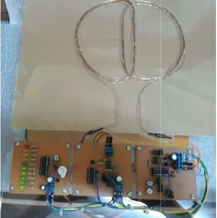
[image:2.595.312.558.216.344.2]ground. Generally, this signal is very complex, so it’s very difficult to describe precisely sensor and metal object interaction taking into account a lot of factors influencing it. A simplified schematic diagram of the Simple Metal detect shown in the Fig 3.1.The photograph of Simple Metal detector is shown in Fig 3.2.
Fig. 3.2. The photograph of Simple Metal detector
4792 Phyu Phyu Mar and Aye Thida Aung
table multi vibrator has no stable states and d forth (oscillates) between two unstable states without any external triggering. These devices are precision timing circuits capable of producing accurate stable mode of operation, ontrolled independently with two external resistors and a signal external capacitor. The threshold and trigger levels normally are two-thirds and
one-.These levels can be altered by use of
The block diagram of simple metal detector
Metal Detector’s operational principle is based upon measurement of the electromagnetic field induced in metal object by probing signal. Probing signal is emitted by coil. The receiving coil receives reflected signal and converts it to electric signal .Transmitting and receiving coils are located in the same body (Metal Detector’s sensor).Receiving coil signal is characterized by value n) so, it’s a vector value . Signal’s phase and amplitude depend upon electromagnetic properties of the searched object, its geometrical dimensions, depth of its geometrical dimensions, depth of its position under the ground surface, and electromagnetic properties of the ground. Generally, this signal is very complex, so it’s very difficult to describe precisely sensor and metal object interaction taking into account a lot of factors influencing it. A simplified schematic diagram of the Simple Metal detector is shown in the Fig 3.1.The photograph of Simple Metal detector
The photograph of Simple Metal detector
3.1. Oscillator and Timing
The master clock generator is a 555 timer IC ( U1 ).The 555 oscillator has two controls.R2 varies the frequency of the main pulse, and R3 varies the pulse width. The frequency of the main pulse determine how many times per second the coil is pulsed. Generally, a higher pulse frequency allows for a faster coil motion and perhaps a little better noise performance, while consuming more power. Varying the main pulse width determines how long the coil is turned on, which can affect depth of detection. The first part which are oscillator and timing circuit are shown in Fig 3.3 and the pho
[image:2.595.308.562.372.568.2]3.4.
Fig. 3.3 Oscillator and Timing circuit
Fig. 3.4. The photograph of Oscillator and Timing circuit
3.2. IB Circuit transmit pulse receiver front
The main device in a IB detector is the c
Transmitter coil (search head, antenna) and Receiver coil. The coil switch serves two functions:
To shirt the coil across the battery voltage, which creates a large coil current;
And to turn the coil current off. During the “on” time , current flowing through the coil creates a
field around the coil. Second part of IB circuit transmit pulse receiver front-end shown in Fig 3.5 and Fig 3.6
3.3. The Advantages of Induction Balance (IB) Detectors Emit an electromagnetic signal of higher intensit
these signals penetrate far deeper into the ground than continuously emitted signals. Cover large areas in less time.
Phyu Phyu Mar and Aye Thida Aung, Design and implementation of simple metal detector
The master clock generator is a 555 timer IC ( U1 ).The 555 controls.R2 varies the frequency of the main pulse, and R3 varies the pulse width. The frequency of the main pulse determine how many times per second the coil is pulsed. Generally, a higher pulse frequency allows for a faster tle better noise performance, while consuming more power. Varying the main pulse width determines how long the coil is turned on, which can affect The first part which are oscillator and timing circuit are shown in Fig 3.3 and the photograph of Fig
3.3 Oscillator and Timing circuit
The photograph of Oscillator and Timing circuit
IB Circuit transmit pulse receiver front-end
The main device in a IB detector is the coils switch. head, antenna) and Receiver coil. The coil switch serves two functions:
To shirt the coil across the battery voltage, which creates a large coil current;
And to turn the coil current off. During the “on” time , current flowing through the coil creates a magnetic field around the coil. Second part of IB circuit transmit
end shown in Fig 3.5 and Fig 3.6
The Advantages of Induction Balance (IB) Detectors Emit an electromagnetic signal of higher intensity and thus, these signals penetrate far deeper into the ground than continuously emitted signals. Cover large areas in less time.
[image:2.595.56.271.566.782.2]Search coil or loop of a induction balance metal detector is simpler than VLF instrument.
Fig 3.5. IB Circuittransmit pulse receive
Fig 3.6. The photograph of IB circuit transmit pulse receiver front-end
A single coil of wire is commonly used for both the transmit and receive functions, while in VLF two coils are needed transmit coil and receive coil. Used two coil.
parameter are coil diameter, number of windings, wire gauge. The standard coil for this design has diameter of 140mm (5.5 inches 0 and 35 turns. The diameter affect the depth and sensitivity, and the number of winding affect the magnetic field.
3.4. Operation of metal detector
The oscillator is constructed using 555 IC. The 555 IC is used in a stable mode to output a 12.5 kHz signal. That signal is fed to the NPN transistor which is used to drive the transmitter coil. The transmitter coil and receiver coil are precisely positioned in “DD” configuration so they are a little overlapped with each other. At the receiver coil side are two operational amplifiers to amplify the received signal, a diode to cut off negative parts and a capacitor to h
stored voltage, and a potentiometer to calibrate the input of display driver IC (LM3914). LM3914 display driver output 10 LEDs to indicate the amplitude of the received signal.
IC is configured in astable mode with 12.5 kHz and 40% cycle. Frequency and duty cycle is adjusted by RV1, RV2. Diode D1 is placed in parallel with RV1, with the cathode on Search coil or loop of a induction balance metal detector is
IB Circuittransmit pulse receiver front-end
The photograph of IB circuit transmit pulse receiver
A single coil of wire is commonly used for both the transmit and receive functions, while in VLF two coils are needed transmit coil and receive coil. Used two coil. Important coil parameter are coil diameter, number of windings, wire gauge. The standard coil for this design has diameter of 140mm (5.5 inches 0 and 35 turns. The diameter affect the depth and sensitivity, and the number of winding affect the magnetic
The oscillator is constructed using 555 IC. The 555 IC is used in a stable mode to output a 12.5 kHz signal. That signal is fed to the NPN transistor which is used to drive the transmitter nd receiver coil are precisely positioned in “DD” configuration so they are a little overlapped with each other. At the receiver coil side are two operational amplifiers to amplify the received signal, a diode to cut off negative parts and a capacitor to hold (sample) the stored voltage, and a potentiometer to calibrate the input of display driver IC (LM3914). LM3914 display driver output 10 LEDs to indicate the amplitude of the received signal. The 555 IC is configured in astable mode with 12.5 kHz and 40% duty cycle. Frequency and duty cycle is adjusted by RV1, RV2. Diode D1 is placed in parallel with RV1, with the cathode on
the capacitor side. This bypasses RV1
the cycle so that the high interval depends only on RV2 C2. The frequency of the 555 IC output is calculated as follows:
TL = 0.693* (RV1)*C2
TH = 0.693* (RV2)*C2
T = 0.693*C2*(RV1 + RV2); F = 1/T = 1.44/(C2*(RV1 + RV2))
Duty Cycle = TH / T = RV2 / (RV1 + RV2)
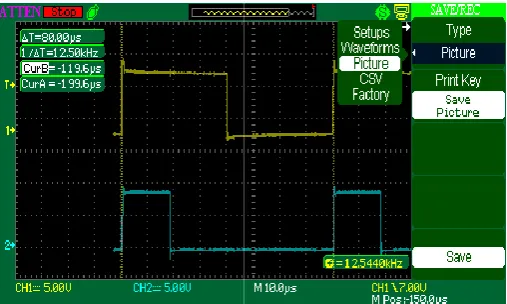
To get 12.5 kHz and 40% duty cycle, show in Fig 3.7The photograph of PWM scope result.
[image:3.595.308.562.202.354.2]RV1 = 6.925 k Ohm , RV2 = 4.61 k Ohm
Fig 3.7. The photograph of PWM scope result
The output from 555 IC is fed to a NPN transistor (2N 2222) through R13 (1k Ohm). The maximum current output of 555 IC is about 200 mA and not enough to directly drive the transmitter coil. An NPN transistor is used to boost the current up to 500mA. Current limiting resistor R
connected in series with the LC pair (transmitter coil in parallel with a capacitor (C10) ).The resis
to be 12.8 Ohm. The collector current of the transistor is
R12 + R = 100 + 12.8 = 128.8 ohm.
One of the most basic parts of the metal detector is search coil. The coils in the metal detector are similar to antenna in that they convert electrical current into electromagnetic energy and vice versa. Unlike to antenna that is intended for EM wave propagation and reception where antenna dimension is based on quarter wavelength, search coils are designed for looking at the close-in magnetic field distortions, and physical size is not related to wavelength. When the transistor at the output of 555 IC switches on current flows through the capacitor (C10) and is charged to Vcc. Because it is connected across an inductor (transmitter coil), current will start to flow through the inductor, building up a magnetic field around it and reducing the charge, and therefore the voltage, on the capacitor. Eventually all the charge on the capacitor will be gone and the voltage across it will reach zero. However, the current will continue unchanged in accordance with
induction, which requires that for the current to change in an inductor, a voltage must be applied to it. However, as the current continues to flow, the capacitor will
of the opposite sign, and its terminal voltage will rise again with reversed polarity. This applies a voltage to the inductor which is now in opposition to its current, so the current now falls. The falling inductor current and rising ca
indicate a transfer of energy from the inductor to the capacitor. When the magnetic field has completely dissipated the current the capacitor side. This bypasses RV1 during the high part of the cycle so that the high interval depends only on RV2 and equency of the 555 IC output is calculated as
F = 1/T = 1.44/(C2*(RV1 + RV2))
/ T = RV2 / (RV1 + RV2)
To get 12.5 kHz and 40% duty cycle, show in Fig 3.7The graph of PWM scope result.
RV1 = 6.925 k Ohm , RV2 = 4.61 k Ohm
The photograph of PWM scope result
The output from 555 IC is fed to a NPN transistor (2N 2222) through R13 (1k Ohm). The maximum current output of 555 not enough to directly drive the transmitter coil. An NPN transistor is used to boost the current up to 500mA. Current limiting resistor R12 (100 Ohm) its
connected in series with the LC pair (transmitter coil in parallel with a capacitor (C10) ).The resistance of the coil is measured to be 12.8 Ohm. The collector current of the transistor is
R = 100 + 12.8 = 128.8 ohm.
[image:3.595.41.285.288.473.2]will momentarily stop, and the charge will again be stored in the capacitor, with a polarity opposite to its ori
will complete half a cycle of the oscillation. The process will then begin again in reverse, even when the transistor is turned off, with the current flowing in the opposite direction through the inductor. So sine wave oscillation occurs in
the resonant frequency of the circuit is given by
f = 12.5 kHz,C = 470 nF
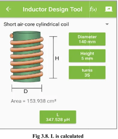
[image:4.595.65.263.203.437.2]L is calculated and found to be 344.9 µH approximately, shown in Fig 3.8.
Fig 3.8. L is calculated
The inductance of a coil depends on its geo
characteristics, the number of turns and the method of winding the coil. The larger the diameter, length, and the larger number of winding turns, the greater its inductance. Inductance of single-layer coils on cylindrical winding forms can be calculated by the formula:
L=(D/10)2*n2/(4.5*D+10*H)
Where L -inductance of the coil, μH;
D - diameter of the coil (diameter of the former), mm; H- high of the coil, mm;
n - number of turns of windings.
The inductance of the coil is known. So we need to c the number of turns and the diameter of the wire. The diameter of the coil is set to 140 mm. So only one parameter, the number of turns, need to be calculated.
L =344.9 µH D = 140 mm H = 5 mm 344.9 x 10-6 = (50/10)2 * n2/ (4.5*50 + 10* 4) N =35 turns (approx:)
LC circuit with the same L and C value are placed in the receiver side. The receiving coil is positioned so that it partially overlaps the transmitting coil. By adjusting the amount of overlap a point can be found where the voltages induced in the receive coil “null”, or cancel out so that little or no electrical output is produced. A metal object entering the field causes an imbalance, resulting in a signal. The rise in the signal’s amplitude is used to indicate the metal’s presence, s
4794 Phyu Phyu Mar and Aye Thida Aung
will momentarily stop, and the charge will again be stored in the capacitor, with a polarity opposite to its original one. This will complete half a cycle of the oscillation. The process will then begin again in reverse, even when the transistor is turned off, with the current flowing in the opposite direction through the inductor. So sine wave oscillation occurs in the LC pair and the resonant frequency of the circuit is given byf = 1/ (2π√LC)
L is calculated and found to be 344.9 µH approximately,
The inductance of a coil depends on its geometrical characteristics, the number of turns and the method of winding the coil. The larger the diameter, length, and the larger number of winding turns, the greater its inductance. Inductance of layer coils on cylindrical winding forms can be
diameter of the coil (diameter of the former), mm;
The inductance of the coil is known. So we need to calculate the number of turns and the diameter of the wire. The diameter of the coil is set to 140 mm. So only one parameter, the
/ (4.5*50 + 10* 4)
LC circuit with the same L and C value are placed in the receiver side. The receiving coil is positioned so that it partially overlaps the transmitting coil. By adjusting the amount of overlap a point can be found where the voltages duced in the receive coil “null”, or cancel out so that little or no electrical output is produced. A metal object entering the field causes an imbalance, resulting in a signal. The rise in the signal’s amplitude is used to indicate the metal’s presence, so
the following stages consist of amplification, accurate conversion to “peak value” (a d.c. signal), and a means of presenting the final output as an audible tone and LED bar graph. Shown in Fig 3.9 and 3.10 are display circuit.
operational amplifier IC is used to amplify the received signal. Of the two op-amps of TL062, the first one is configured as a voltage follower that output half the supply voltage with R4, R5 divider. The voltage at the non
of the voltage follower is 6V. That output is used to bias (level up) the incoming signal coming out of receive coil. By setting at the mid-supply voltage, maximum gain without distortion can be achieved. That signal is fed to the second op
is set up as a non-inverting amplifier with adjustable gain. The gain is calculated as follows.
Av(max) = RV3/R2 = (250k/1k) = 250
[image:4.595.307.561.247.504.2]Fig 3.9. Display Board LED bar graph
Fig 3.10 The photograph of LED bar graph
So at the maximum gain, the output signal is 250 times greater than input. But practically the gain used in the project is around 40 which is enough for the output signal to swing at its maximum amplitude of 0 to +12 V. The output of the amplified signal is fed to the LM3914 display driver through a
Phyu Phyu Mar and Aye Thida Aung, Design and implementation of simple metal detector
the following stages consist of amplification, accurate conversion to “peak value” (a d.c. signal), and a means of presenting the final output as an audible tone and LED bar graph. Shown in Fig 3.9 and 3.10 are display circuit. TL062 r IC is used to amplify the received signal. amps of TL062, the first one is configured as a voltage follower that output half the supply voltage with R4, R5 divider. The voltage at the non-inverting input and output s 6V. That output is used to bias (level up) the incoming signal coming out of receive coil. By setting supply voltage, maximum gain without distortion can be achieved. That signal is fed to the second op-amp which mplifier with adjustable gain. The
Av(max) = RV3/R2 = (250k/1k) = 250
Display Board LED bar graph
Fig 3.10 The photograph of LED bar graph
So at the maximum gain, the output signal is 250 times greater than input. But practically the gain used in the project is around 40 which is enough for the output signal to swing at its maximum amplitude of 0 to +12 V. The output of the s fed to the LM3914 display driver through a
[image:4.595.307.558.523.718.2]potentiometer (RV4) to make calibration for ground balancing. There are ten LEDs on the output of LM3914 IC. The display mode of the output LEDs are selected as bar graph mode so it is easy to see the signal level. There is also a buzzer for audio output. Whenever there is at least one LED at the output of LM3914 turned on or the input signal from the capacitive sensor becomes active (low level), 2N 5551 transistor is turned on and drives the buzzer. Most sands and soils contain some amount of iron. They may also have conductive properties due to the presence of salts dissolved in the ground water. The result is that a signal is received by the detector due to the ground itself which may be hundreds of times stronger than the signal resulting from small metal objects buried at modest depths. At this condition the bar graph may display some value that is not really valid. And so it should be lowered to ground level (no LEDs turned on) manually by adjusting potentiometer RV4. That calibration is known as ground balancing. Showing the Table-3.1 gives the distances at which various objects can be detected.
Table 3.1. The sensitivity of the metal locator in free air
Object High sens 2p Coin 6
Beer can 8
Copper 6
Steel ruler 12
Gold ring 6
Conclusion
Metal detector is portable hand-held metal detector designed for searching to human body, luggage and mails for all kinds of metal articles and weapons. It can be widely used for security inspection and access control by airports, customs, seaports, railway stations, prisons important gateways, light industries and all kinds of public events. Improved detection frames for the uniform sensitivity over the entre walk-through area from top to bottom. Higher sensitivity with lower false alarm rate 100 sensitivity levels and 6 working frequencies for each program. Auto counting of both pass through and alarmed population.
Metal detectors used in searching for buried metallic objects are similar in concept to those used for geophysical exploration. All such instruments depend on the measurement of a magnetic field associated with eddy currents induced in the target by a primary magnetic field.
3.6. Application of metal detectors
A metal detector is an electronic instrument which detects the presence of metal nearby. Metal detectors are useful for finding metal inclusions hidden within objects, or metal objects buried underground. They often consist of a handheld unit with a sensor probe which can be swept over the ground or other objects. If the sensor comes near a piece of metal this is indicated by a changing tone in earphones, or a needle moving on an indicator. Usually the device gives some indication of distance; the closer the metal is, the higher the tone in the earphone or the higher the needle goes. Another common type are stationary "walk through" metal detectors used for security screening at access points in prisons, courthouses, and airports to detect concealed metal weapons on a person's body.
REFERENCES
Bruschini C 2006 ‘A multidisciplinary Analysis of Frequency Domain Metal Detectors for Humanitarain Demining ‘(PhD Thesis: Vrije Universiteit Brussel)
http://home.howstuffworks.com/metal-detector3.htm http://www.wikipedia.org wiki, Metal Detector
Ishikawa J, Furuta K 2006 ‘ Anti- personnel Landmines Detection for Humanitarian Demining ‘(London: Springer- Verlag London Limited)
Roland J .Kamrowski, Metal Detecting-Learning How the Easy Way! (book.google.com.mm)
Sheman Troy, Lulu.com, 4014,’How to Use a Metal Detector for Treasure Hunting: M et al Detecting Tips and Guide You Need to Read (book.google.com.mm).