ISSN Online: 2165-3860 ISSN Print: 2165-3852
DOI: 10.4236/ojfd.2019.91007 Mar. 28, 2019 92 Open Journal of Fluid Dynamics
Aerodynamic Optimization of a Centrifugal Fan
Using Response Surface Methodology
Tao Liu, Yingkun Zhang, Kunhang Li, Yu Wang, Jingyin Li
*School of Energy and Power Engineering, Xi’an Jiaotong University, Xi’an, China
Abstract
In this paper, the optimization scheme of a centrifugal fan under the con-straints of the total pressure difference, efficiency and shaft power was carried out. The blade inlet angle β1A and the blade outlet angle β2A of the centrifugal
impeller were optimized using the Response Surface Methodology (RSM). Nine optimization cases were presented. The aerodynamic performance and the flow field of the optimized model were carefully compared with the orig-inal model. The results show that the total pressure difference and the to-tal-pressure efficiency increase by 5.7% and 4.2% respectively after the opti-mization. Compared with the original fan, the flow field inside the impeller of the optimized fan has been improved. The flow separation existing around the blade suction surface outlet is suppressed significantly. For fields in the volute, the optimization scheme has reduced the local vortex intensity and weakened the vortex scale. The flow field stability around the volute tongue is also correspondingly improved.
Keywords
Centrifugal Fan, Optimization, Response Surface Methodology
1. Introduction
Centrifugal fan, a widely used centrifugal machinery, plays an important role in industry. The centrifugal impeller is the key component of the centrifugal fan and it has a significant effect on the performance of the centrifugal fan. Lots of work on designing and optimizing the centrifugal impeller has been done over the past decades. The traditional engineering design method of the impeller was investigated by Li [1]. He studied the method to design some parameters of the impeller, including the meridian lines, blade number, blade inlet angle, blade outlet angle and so on. However, the traditional design method depends
signifi-How to cite this paper: Liu, T., Zhang, Y.K., Li, K.H., Wang, Y. and Li, J.Y. (2019) Aerodynamic Optimization of a Centrifug-al Fan Using Response Surface Methodol-ogy. Open Journal of Fluid Dynamics, 9, 92-105.
https://doi.org/10.4236/ojfd.2019.91007
Received: February 25, 2019 Accepted: March 25, 2019 Published: March 28, 2019
Copyright © 2019 by author(s) and Scientific Research Publishing Inc. This work is licensed under the Creative Commons Attribution International License (CC BY 4.0).
DOI: 10.4236/ojfd.2019.91007 93 Open Journal of Fluid Dynamics
cantly on the engineering practice, which is a limit in meeting the diverse design objectives. Besides, the effects of some important design parameters on the aerodynamic performance of the centrifugal fan were investigated numerically, including the blade number [2], the blade loading [3] [4] and the meridional channel of the impeller [5].
With advances in numerical algorithms and computer hardware, the Compu-tational Fluid Dynamics (CFD) has been widely used as a design tool. On the ba-sis of CFD, several strategies have been applied for the optimization. Both ge-netic algorithms (GAs) [6] [7] and particle swarm optimization (PSO) methods
[8] [9] are widely used. In addition, surrogate-based optimization (SBO) [5] [10]
and Artificial Neural Network (ANN) [11] [12] become popular recently in the aerodynamic shape optimization of turbomachinery. But their requirement of the computational source is considerable.
Response surface method (RSM), as a global optimization method, is also widely used in the optimization procedure of turbomachinery. The method can utilize the information collected by different tools and perform tasks in parallel easily [13]. Guo et al. [14] studied a geometrical optimization for a mini-centrifugal com-pressor. The RSM was used in obtaining the first-order and the second-order regression models in the procedure. The results indicated a considerable im-provement of the pressure ratio and the efficiency. Benim et al. [15] optimized an airfoil shape for small horizontal axis wind turbines by combining the CFD analysis with RSM and the Biobjective Mesh Adaptive Direct Search (BiMADS) algorithm. Their results demonstrated that the method used in the optimization of the blade shape was effective. In the research of Jang et al. [16], RSM was used to the shape optimization of a stator blade in a single-stage transonic axial com-pressor. Adiabatic efficiency was selected as an objective function of the skew angle at the mid-span section and the skew angle at the tip of the stator blade. After optimization, the adiabatic efficiency increased by 2.5% due to the sup-pression of the separation on the suction surface of the stator. Tang et al. [17]
proposed a gradient-enhanced response surface model (GERSM), a new method used in the optimization of turbomachinery blades. The transonic NASA Rotor 67 blade row was optimized at the design speed near the peak efficiency using both the steepest decent optimization (SDO) and GERSM. The results showed that, compared with the traditional response surface, GERSM proved to be far more robust and accurate in the prediction of both the function value and the gradient. Kaibin et al.[18] presented an optimization strategy for a centrifugal impeller with the constraint on efficiency at the stall point. The impellers with different angular momentum distributions determined by RSM were generated and simulated. The optimal impeller was obtained, and the performance was improved greatly. The result indicated that RSM was effective in the optimiza-tion of the centrifugal impeller.
characteris-DOI: 10.4236/ojfd.2019.91007 94 Open Journal of Fluid Dynamics
tics. In this paper, both the aerodynamic performance and the flow characteris-tics of the centrifugal fan were analyzed in detail, which is beneficial to under-stand which phenomena are to be either controlled or exploited to improve the aerodynamic performance. The paper is organized as follows. In Section 2, the main parameters of the original model are presented and the numerical ap-proach is introduced. The optimization of the centrifugal impeller based on RSM is carried out in Section 3, and the nine cases under the optimization scheme are given. In Section 4, the optimization results are presented, and the flow charac-teristics of the impeller and fan are investigated in detail. The paper ends with conclusions in Section 5.
2. Physical models and Numerical Approach
2.1. Parameters of the Original Model
Table 1 shows the main parameters of the original fan. The total pressure dif-ference of the fan is 1328 Pa, and the shaft power is 6.1 kW. Table 2 shows the main parameters of the original impeller designed by the traditional engineering design method. The impeller is designed with the rotating speed of 1450 r·min−1
and has 15 back-bend blades. The shroud surface of the impeller is curved while the hub surface is a plane. The blade profile is designed in uniform deceleration method, which assures that the blade angle reduces in a constant ratio from blade outlet to inlet.
2.2. Grid Generation and Boundary Conditions
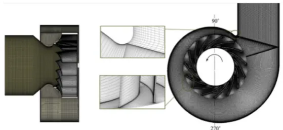
The volute and the collector are designed according to the engineering expe-rience, which have a structured grid for the simulation. The hexahedral struc-tured grid is applied in both the original impeller and the optimized impeller by using the software Turbo-Grid. The grid distribution of the fan is presented in
Figure 1. The validation of the grid was conducted for 5 cases, and the case with the total grid number of 7.8 million was adopted. In the adopted grid case, the grid number of the impeller is 2.5 million while the collector and the volute are 1.3 million and 4 million, respectively.
To analyze the flow field and the aerodynamic performance of the fan, a nu-merical investigation with the K-ω SST model in CFX was carried out. Inlet boundary condition, with the flow rate being set to 14,000 m3·min−1, was given
on the inlet of the collector. The outlet boundary condition was given on the vo-lute outlet, and the outlet static pressure was set as 0 Pa. The interfaces between the impeller and the stationary elements (collector and volute) were set as the frozen rotor. Numerical cases were regarded as convergent when the Root Mean Square (RMS) of residual is lower than 10−5.
3. Response Surface-Based Optimization Scheme
3.1. Optimization Factors and Schemes
DOI: 10.4236/ojfd.2019.91007 95 Open Journal of Fluid Dynamics
have great effects on the aerodynamic performance of the centrifugal fan. In this study, Central Composite Design (CCD), one method of RSM, was used due to its good performance in estimating the objective function. The CCD method requires central points and axial points to complete the design, each factor has five levels as shown in Table 3.
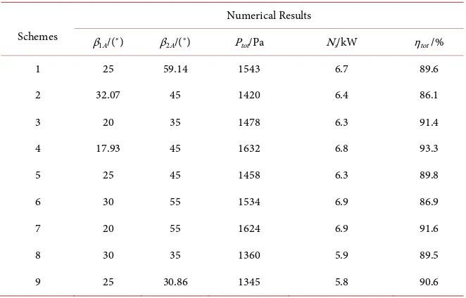
[image:4.595.229.516.247.379.2]After identifying the factors and levels, a multi-objective optimization prob-lem is formulated with three response variables: total pressure difference, shaft power and total-pressure efficiency. The design of experiment scheme in the CCD has 9 cases after removing the 4 same cases. All the nine cases in the opti-mization schemes as well as the CFX results of the total pressure difference, shaft power and total-pressure efficiency are listed in Table 4.
[image:4.595.209.542.432.485.2]Figure 1. Grid distribution of the fan.
Table 1. Main parameters of the original fan.
Variables Pressure Total (Pa)
Shaft Power
(kW)
Total-Pressure Efficiency
(%)
Flow Rate (m3·min−1)
Rotational Speed
(r·min−1) Media
[image:4.595.209.541.515.635.2]Values 1328 6.1 84.0 14,000 1450 air
Table 2. Main parameters of the original impeller.
Variables Values
Impeller outlet diameter D2/mm 700
Impeller inlet diameter D0/mm 480
Number of blades 15
Impeller outlet width b2/mm 175
Impeller inlet width b1/mm 245
Blade outlet angle β2A/˚ 45
Blade inlet angle β1A/˚ 25
Table 3. Factors and levels.
Factors
Levels
−1.414 −1 0 1 1.414
β1A/˚ 17.93 20 25 30 32.07
DOI: 10.4236/ojfd.2019.91007 96 Open Journal of Fluid Dynamics Table 4. Schemes and numerical results of the design of experiment.
Schemes
Numerical Results
β1A/(˚) β2A/(˚) Ptot/Pa Ns/kW ηtot /%
1 25 59.14 1543 6.7 89.6
2 32.07 45 1420 6.4 86.1
3 20 35 1478 6.3 91.4
4 17.93 45 1632 6.8 93.3
5 25 45 1458 6.3 89.8
6 30 55 1534 6.9 86.9
7 20 55 1624 6.9 91.6
8 30 35 1360 5.9 89.5
9 25 30.86 1345 5.8 90.6
3.2. The Sensitivity Analysis of the Impeller Parameters
With the total pressure difference being targeted, the following second order fit-ting function was obtained from the RSM result:
2 2
1 2 1 2 1 2
-
tot A A A A A A
P =A Bβ +Cβ +Dβ β +Eβ +Fβ (1)
here, A, B, C, D, E and F represent the constant number with the value of 2617.70, 101.20, 3.91, 0.14, 1.64 and 0.001 respectively. The fitting function was obtained by using the Design-Expert, a useful software for RSM analysis. It is observed that the P-value of the fitting function is lower than 0.0001, which in-dicates the fitting function is significant.
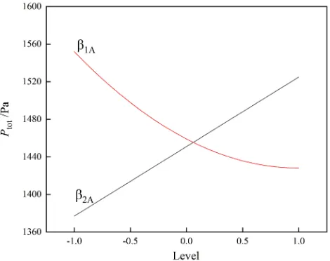
With the Design-Expert, the sensitivity analysis for the total pressure differ-ence of the given nine cases is presented in Figure 2. The figure indicates that the blade inlet angle β1A and the blade outlet angle β2A are sensitive for the total
pressure difference of the impeller, and β2A is more sensitive than β1A. As β2A
in-creases, the ability to generate energy of impeller will be enhanced. That is the reason why the total pressure difference behaves a positive correlation distribu-tion. On the contrary, as β1A increases, the total pressure difference curve shows
a gradually decreasing trend. This phenomenon can be illustrated that the large blade inlet angle may cause the energy loss of the impact of the flow forces.
The second order fitting function for the shaft power can be expressed as:
2 2
1 2 1 2 1 2
s A A A A A A
N = −A Bβ −Cβ +Dβ β +Eβ −Fβ (2)
here, A, B, C, D, E and F represent the constant number with the value of 11.6, 0.45, 0.0085, 3, 0.00675 and 0.0000625 respectively. The P-value of the fitting function is lower than 0.0001, which also indicates the fitting function is reliable.
In Figure 3, the sensitivity analysis for the shaft power of the given nine cases is presented. It can be seen that the blade inlet angle β1A and the blade outlet
DOI: 10.4236/ojfd.2019.91007 97 Open Journal of Fluid Dynamics
decreases slowly and then increases slowly with the β1A increasing. However, the
shaft power has a positive correlation distribution trend as β2A increases. It can
be seen that for the shaft power, the influence of β2A exceeds that of β1A. The
second order fitting function for the total-pressure efficiency is shown as below:
1 2 1 2
tot A B A C A D A A
η = + β + β − β β (3)
[image:6.595.256.491.301.487.2]here, A, B, C and D represent the constant number with the value of 86.62, 0.21, 0.30 and 0.014. It is found that the fitting function is significant because the P-value of the fitting function is lower than 0.0001.
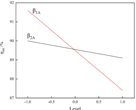
Figure 4 shows the sensitivity analysis for the total-pressure efficiency of the given nine cases. As Figure 4 shows, both the blade inlet angle β1A and the blade
outlet angle β2A have an important influence on the total-pressure efficiency. The
total-pressure efficiency has a negative correlation distribution with the two fac-tors increasing. Compared to the blade outlet angle β2A, the blade inlet angle β1A
[image:6.595.256.491.519.704.2]has a greater impact on the total-pressure efficiency.
Figure 2. The sensitivity analysis of the total pressure difference.
DOI: 10.4236/ojfd.2019.91007 98 Open Journal of Fluid Dynamics Figure 4. The sensitivity analysis of the total-pressure efficiency.
4. Results and Discussion
4.1. Optimization Results
The goal of optimization is to obtain the maximum values of the total pressure difference and the total-pressure efficiency. In addition, its shaft power needs to be less than 6.5 kW. We obtained the optimal value of β1A and β2A from the
fit-ting function. The values of them are 17.6˚ and 42.5˚ respectively. The optimized model was built and the optimization results were obtained by CFX. Table 5
shows the simulated results. It can be seen that the total pressure difference and the total-pressure efficiency increase by about by 6.4% and 4.6% respectively.
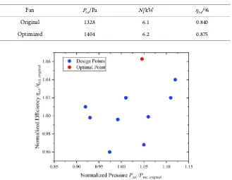
Figure 5 shows the distribution of the total pressure difference and the to-tal-pressure efficiency in the course of optimization. In the optimal point, the total-pressure efficiency is highest among design cases and the improvement of the impeller’s performance is significant.
The fan with the optimized impeller is selected to be the optimized fan and simulated by CFX. The numerical results of it are presented in Table 6. The total pressure difference and the total-pressure efficiency increase by about 5.7% and 4.2% respectively. And the shaft power is less than the limit value 6.5 kW. The aerodynamic performance of the fan is improved significantly, which indicates that the RSM used in the optimization procedure is effective.
4.2. Analysis of the Impeller Internal Flow Condition
DOI: 10.4236/ojfd.2019.91007 99 Open Journal of Fluid Dynamics
impeller. As shown in Figure 6(b), it can be seen that the total pressure in the impeller increases uniformly after optimization. The scales of both the low pres-sure region and the high energy region decrease significantly. It indicates that the impact of the flow forces on the impeller has been reduced and the flow se-paration has been suppressed effectively.
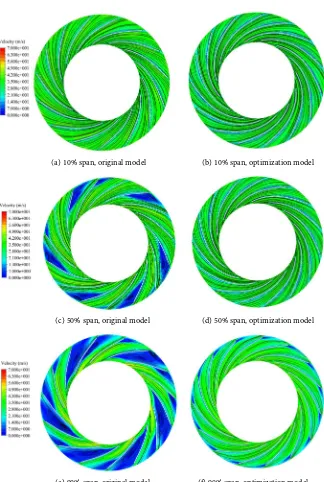
Figure 7 presents the relative velocity distribution in the impeller. Figure 7(a)
and Figure 7(b) show that the velocity distributions in the impeller for both models are even near the hub. There is little difference between the original im-peller and the optimization imim-peller.
[image:8.595.209.539.376.426.2]Figure 7(c) and Figure 7(d) show that the velocity distributions at 50% span of the impeller for both models are different obviously. The velocity distribution for the original model is extremely uneven. Due to the large impeller outlet an-gle, the expansion ratio of impeller passage is too large, which results in severe flow separation near the exit of the suction surface. While for the optimization model, the expansion ratio of impeller passage is moderate and the flow separa-tion near the exit of the sucsepara-tion surface decreases clearly, which indicates that the optimization impeller could take a better control of the flow.
Table 5. Performance comparison between the original impeller and the optimized im-peller.
Impeller Ptot /Pa Ns /kW ηtot /%
Original 1458 6.3 0.898
[image:8.595.212.541.451.706.2]Optimized 1551 6.4 0.939
Table 6. Performance comparison between the original fan and the optimized fan.
Fan Ptot/Pa Ns/kW ηtot/%
Original 1328 6.1 0.840
Optimized 1404 6.2 0.875
DOI: 10.4236/ojfd.2019.91007 100 Open Journal of Fluid Dynamics (a) original model (b) optimization model
Figure 6. Total pressure distribution at 50% span of the impeller.
(a) 10% span, original model (b) 10% span, optimization model
(c) 50% span, original model (d) 50% span, optimization model
[image:9.595.211.535.203.685.2]DOI: 10.4236/ojfd.2019.91007 101 Open Journal of Fluid Dynamics
As Figure 7(e) shows, the flow separation occupies almost the entire passage near the shroud of the impeller due to the sudden expansion of the cross-section when air enters the impeller from the collector. In addition, the improper ex-pansion ratio of impeller passage worsens the flow separation and produces large separation losses. In contrast, the flow separation almost disappears for the op-timization model as Figure 7(f) shows, which indicates that the expansion ratio of impeller passage decreases properly and matches the curved shroud better. Therefore, the flow inside the impeller is greatly improved and the pressure loss is reduced significantly.
4.3. Analysis of the Fan Internal Flow Condition
Figure 8 shows the vortex core distribution inside the fan. The internal vortex intensity of the original fan is 1163.9 s−1, which is reduced to 946.2 s−1 after
op-timization. For the optimization model, the vortices are suppressed effectively, which would improve the work capacity of the impeller and the aerodynamic performance of the fan.
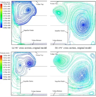
Figure 9 shows streamlines distribution on 90˚ and 270˚ sections inside the volute. Angle orientation of the sections is shown in Figure 1. Due to the sudden expansion of the cross-section from the impeller outlet to the volute, vortices will appear inside the volute. Figure 9(a) presents the streamlines inside the vo-lute on 90˚ cross-section for the original model. It can be seen that the flow near the impeller outlet is extremely uneven and a large-scale vortex is formed in the volute. In contrast, for the optimization model, the flow near the impeller outlet is more uniform as shown in Figure 9(c). Besides, as Figure 9(b) shows, on 270˚ cross-section, the scale of the vortex mentioned above becomes larger and a smaller vortex appears at the back of the collector, which will cause more pres-sure loss. In Figure 9(d), the effect of the large-scale vortex on the flow field near the impeller outlet is weakened and the core of the vortex is father away from the impeller outlet.
DOI: 10.4236/ojfd.2019.91007 102 Open Journal of Fluid Dynamics
more even after optimization, which could reduce the pressure loss and the noise.
5. Conclusions
The optimization procedure based on Response Surface Methodology (RSM) is conducted on a centrifugal fan. The blade inlet angle β1A and the blade outlet
an-gle β2A of the centrifugal impeller were taken as the optimization factors, and
some improvements were obtained. The main results of this work can be con-cluded as follows:
[image:11.595.217.535.222.333.2] [image:11.595.210.537.366.697.2](a) original model (b) optimization model Figure 8. The distribution of the vortex core inside the fan.
(a) 90˚ cross-section, original model (b) 270˚ cross-section, original model
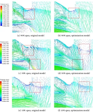
DOI: 10.4236/ojfd.2019.91007 103 Open Journal of Fluid Dynamics (a) 90% span, original model (b) 90% span, optimization model
(c) 50% span, original model (d) 50% span, optimization model
[image:12.595.210.536.68.460.2](e) 10% span, original model (f) 10% span, optimization model Figure 10. The velocity vector nearby the volute tongue.
1) In the sensitivity analysis, the blade outlet angle β2A is found to be more
sensitive to the total pressure difference and the shaft power; while the blade in-let angle β1A is more sensitive to the total-pressure efficiency. The two key
para-meters have great impacts on the aerodynamic performance of the centrifugal impeller and the fan.
2) The flow separation is severe near the shroud of the impeller outlet and the exit of the suction surface. Through the optimization, the reduced expansion ra-tio of impeller passage as well as the impact of the flow forces on the blade sup-pressed the local flow separation significantly.
3) The large scale vortices existing in the regions between the impeller shroud and the volute are suppressed. The flow field stability around the volute tongue is also improved, and the local fields with low-energy fluid are reduced.
DOI: 10.4236/ojfd.2019.91007 104 Open Journal of Fluid Dynamics
the centrifugal impeller as optimization parameters has improved the total pres-sure difference and the total-prespres-sure efficiency by 5.7% and 4.2% respectively.
Acknowledgements
This work was financially supported by the National Key R&D Program of Chi-na (2018YFB0606101) and the Natural Science Foundation of ChiChi-na (51876158 and 51776145).
Conflicts of Interest
The authors declare no conflicts of interest regarding the publication of this pa-per.
References
[1] Li, Y.Q. (1981) Fan. China Machine Press, Beijing.
[2] Amladimanesh, A., Ajam, H. and Nezhad, H. (2015) Numerical Study of Blade Number Effect on the Performance of 3D FC Centrifugal Fan. International Journal of Mechatronics, Electrical and Computer Technology, 5, 2109-2119.
[3] Shibata, T., Yagi, M., Nishida, H., Kobayashi, H. and Tanaka, M. (2011) Perfor-mance Improvement of a Centrifugal Compressor Stage by Increasing Degree of Reaction and Optimizing Blade Loading of a Shrouded 3D Impeller. Journal of Turbomachinery, 133, 1305-1315. https://doi.org/10.1115/1.4000565
[4] Zangeneh, M., Amarel, N., Daneshkhah, K. and Krain, H. (2011) Optimization of 6.2:1 Pressure Ratio Centrifugal Compressor Impeller by 3D Inverse Design. Pro-ceedings of ASME Turbo Expo 2011, Vancouver, 6-10 June 2011, 2167-2177. https://doi.org/10.1115/GT2011-46505
[5] Kim, J.H., Choi, J.H. and Kim, K.Y. (2010) Surrogate Modeling for Optimization of a Centrifugal Compressor Impeller. International Journal of Fluid Machinery and Systems, 3, 29-38. https://doi.org/10.5293/IJFMS.2010.3.1.029
[6] Chen, X. and Agarwal, R.K. (2013) Shape Optimization of Airfoils in Transonic Flow Using a Multi-Objective Genetic Algorithm. Journal of Aerospace Engineer-ing, 228, 1654-1667.
[7] Torshizi, S.M., Benisi, A.H. and Durali, M. (2017) Multilevel Optimization of the Splitter Blade Profile in the Impeller of a Centrifugal Compressor. Scientia Iranica, 24, 707-714. https://doi.org/10.24200/sci.2017.4055
[8] Xia, C.C., Jiang, T.T. and Chen, W.F. (2016) Particle Swarm Optimization of Aero-dynamic Shapes with Nonuniform Shape Parameter-Based Radial Basis Function.
Journal of Aerospace Engineering, 30, Article ID: 04016089.
[9] Zhao,Y.S., Liu, B., Xiao, C.M. and Xiao, F.L. (2016) Optimization of Tandem Blade Based on Improved Particle Swarm Algorithm. ASME Turbo Expo 2016: Turbo-machinery Technical Conference and Exposition, Seoul, 13-17 June 2016, V02CT45A015.
[10] Andrés-Pérez, E., González-Juárez, D., Martin-Burgos, M.J., Carro-Calvo, L. and Salcedo-Sanz, S. (2017) Influence of the Number and Location of Design Parame-ters in the Aerodynamic Shape Optimization of a Transonic Aerofoil and a Wing through Evolutionary Algorithms and Support Vector Machines. Engineering Op-timization, 49, 181-198. https://doi.org/10.1080/0305215X.2016.1165568
Ap-DOI: 10.4236/ojfd.2019.91007 105 Open Journal of Fluid Dynamics proach to Compressor Performance Prediction. Applied Energy, 86, 1210-1221. https://doi.org/10.1016/j.apenergy.2008.06.006
[12] Chu, F., Wang, F., Wang, X. and Zhang, S. (2014) A Hybrid Artificial Neural Net-work-Mechanistic Model for Centrifugal Compressor. Neural Computing and Ap-plications, 24, 1259-1268. https://doi.org/10.1007/s00521-013-1347-5
[13] Sevant, N.E., Bloor, M.I. and Wilson, M.J. (2000) Aerodynamic Design of a Flying Wing Using Response Surface Methodology. Journal of Aircraft, 37, 562-569. https://doi.org/10.2514/2.2665
[14] Guo, S., Duan, F., Tang, H., Lim, S.C. and Yip, M.S. (2014) Multi-Objective Opti-mization for Centrifugal Compressor of Mini Turbojet Engine. Aerospace Science and Technology, 39, 414-425. https://doi.org/10.1016/j.ast.2014.04.014
[15] Benim, A., Diederich, M. and Pfeiffelmann, B. (2018) Aerodynamic Optimization of Airfoil Profiles for Small Horizontal Axis Wind Turbines. Computation, 6, 34. https://doi.org/10.3390/computation6020034
[16] Jang, C.M. and Kim, K.Y. (2005) Optimization of a Stator Blade Using Response Surface Method in a Single-Stage Transonic Axial Compressor. Journal of Power and Energy, 219, 595-603. https://doi.org/10.1243/095765005X31298
[17] Tang, X., Luo, J. and Liu, F. (2017) Aerodynamic Shape Optimization of a Transon-ic Fan by an Adjoint-Response Surface Method. Aerospace Science and Technology, 68, 26-36. https://doi.org/10.1016/j.ast.2017.05.005