Engineering, 2011, 3, 485-490
doi:10.4236/eng.2011.35056 Published Online May 2011 (http://www.SciRP.org/journal/eng)
Experimental and Numerical Study of the Effect of
Surround Protection Technique on the Strain
Measurement for Offshore Jacket Platform
Yongjun Xu
Key Laboratory for Hydrodynamics and Ocean Engineering, Institute of Mechanics, Chinese Academy of Sciences, Beijing, China
E-mail: [email protected]
Received March 3,2011; revised March 29, 2011; accepted April 6, 2011
Abstract
For strain measurement on offshore jacket platform in deep water, waterproof of strain foil is always an im-portant issue, especially, due to the high pressure in deep water. The waterproof is difficult in two places, one is between the matrix structure and the protection structure, and another is between the lead wires and the protection structure. The surround protection technique discussed in this paper is conventional and ideal, and can be operative for a long time, up to five years. In this method, a metal case and tube is added on the local position, which increases the local rigidity, but the effect on the measurement of strain is not well stud-ied. In this paper, the effect of the surround protection technique on the strain measurement is studied by us-ing numerical and experimental methods, and the results show that the measurement error is well in the range permitted by engineering practice.
Keywords:Offshore Jacket Platform, Strain Measurement, Strain Foil, Surround Protect/Waterproof Technique
1. Introduction
Electrical resistance strain gages are widely used for stress analysis based on strain measurement for various metal structures in hostile environment, such as pressure vessel, submarine, deep-water vehicle, submerged pipe-line and offshore jacket platform. Due to the high pres-sure in deep water, the strain gages have to be isolated from the surrounding environment to work properly. There are two main kinds of protection/waterproof tech-niques, one is the chemical waterproof technique for the gage to be isolated from the environment by coating with a certain chemical substance, and another is the me-chanical sealing technique for the gage to be isolated from the environment by some solid enclosure. In the cases of chemical protections, with such as bitumen compound [1], filled epoxy [2], self-vulcanizing rubber electrical tape and rubber-to-metal cement [3,4], and epoxy resin and polyisobutylene [5,6], the water-proof/protection efficiency depends on the adhesive strength between the protective coating materials and the matrix, protective coating materials and the lead cable,
and the additional pressure effects are included in the strain measured. The pressure effect was studied by sev-eral investigators [7-9]. In the cases of mechanical seal-ing [2,6], waterproof/protection efficiency depends on the annular gasket between the matrix structure and the surround metal shell, and the strain field can be signifi-cantly changed at the location of the measurements. Strain gages [9-14] will always be one of the best strain measurement methods for various metal structures. Xu Y. J. et al. [15-17] carried out an intensive study of the spot welding flake strain gauge/sensor. In practice, it is some-times very difficult to adhere, cure and post cure the strain gauges on the spot, especially during the short time limit permitted by the project. Some pre-work, such as adhering, curing and post curing, and some preliminary seal work, can be done in the laboratory by flake strain gauge/sensor technology. Then, we only need to weld the flake to the matrix in the field.
Y. J. XU 486
a depth of about 100 - 150m. They are usually built from tubular steel members. These structures have a very short vibration period ranging from 2 to 8 s. Apart from the operational loads, they also subject to environmental loads such as wind, wave, tidal current, ice and earth-quake loads. The safety monitoring and assessment tech-niques of Ocean Platform Structure [18] are very impor-tant, and the long-term strain/stress measurement is one of the key issues for the jacket platform. The surround protection technique [2,19] is a conventional and ideal method, which can be used to protect/waterproof the strain gage for a period up to five years. This protection method adds a metal case and tube on the local position which increases the local rigidity, but its effect on the measurement of strain is not clear. In this paper, the ef-fect is studied by using numerical and experimental methods.
2. Some Protection/Waterproof Techniques
Basic Protection Requirements
Mark the area around the gauge to be covered, before covering the gauge.
Measure and record the gauge grid resistance and the resistance-to-ground after removal of soldering flux but before applying coating.
Mix two parts of materials thoroughly and take care of unmixed materials on the container surfaces.
‘Wet’ the surface with a small amount of materials before the full protection procedure.
Do not smooth the protective covering but have a high build-up at the edge.
Avoid sharp corners at the coating edge, as break-down can begin at such places.
Remove, where practicable, possible breakdown points from the structure surface (e.g. terminals).
Use pressure-tested cables and anchor them, both inside and outside the coating area, before coating.
Degrease all cable cores in contact with the coating and ensure separate entry into the coating (which ap-plies also to ribbon cables).
Make the cable/coating interface as long as possible.
2.1. Short-Term Protection Technique
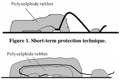
When a relatively short-term protection is required, up to 6 months in wet conditions, the technique illustrated in Figure 1 proves to be satisfactory. Provided that the above basic protection requirements are observed, this technique will provide adequate gauge protection at pressures up to 2500lbf/in2 (1757673kgf/m2).
2.2. Over-Lap Protection Technique
Over-lap protection technique differs fundamentally from the ‘short-term’ protection technique in that it is a ‘double barrier’ technique, although both barriers can be of the same material, as illustrated in Figure 2. The ca-ble/coating interface is double with respect to the ‘short-term’ protection technique, to increase the life of the protection structure. Using the ‘over-lap’ protection technique, an adequate gauge protection in wet condi-tions for up to 12 months can be expected.
A ‘three barriers’ over-lap protection technique [14] was proven to be successful in the strain measurement in sea water of 10 meters deep for Chengbei-25A jacket platforms for about 6 months.
2.3. Long-Term Technique
Neither the short-term protection technique nor the over-lap protection technique provides really substantial mechanical protection in addition to the protection against moisture. In case where the mechanical protec-tion is necessary (e.g. for oil rigs, jacket platform), an overall metal surround and cable entry can be used. The surround technique is illustrated in Figure 3, and this technique could adequate gauge protection in deep water for up to 5 years.
A surround protection technique [19] was proven to be successful in the strain measurement in sea water of 40 meters deep for W11-4 jacket platform (as Figure 4 shows) for about 3 years in south sea of China.
3. Experimental Study on the Effect of
Surround Protection Technique
3.1. Specifications and Geometrical Data of Prototype Surround Case
A steel surround protection case is employed in this
[image:2.595.326.527.570.710.2]Figure 1. Short-term protection technique.
Y. J. XU 487
study as illustrated in Figure 5(a), and the corresponding geometric dimensions are shown in Figure 5(b).
3.2. Specifications and Installation of Test Facilities
It is well known that the stress/strain state indicates the local extension-compression characteristics of the off-shore jacket platform. A steel plate sample of 0.2 m long, 0.1 m width and 0.01 m thick is employed, and six bolt shanks (M6) are welded to match with the six holes on the surround case. An annular gasket (3 mm) is closely pressed between the case and the sample by screwing six nuts as illustrated in Figure 6(a). The tension-compres- sion tests are carried out in LETRY(10T) as shown in Figure 6(b).
3.3. Experimental Results
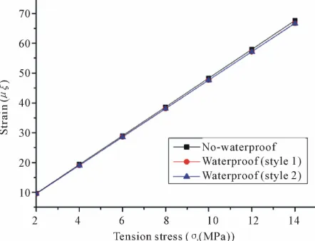
After several pre-loading and unloading processes, we measure the strains at the center point by loading and unloading with stress t of 8 Mpa, 10 Mpa, 12 Mpa and 14 Mpa. A group of average strains based on two loading and unloading processes are obtained and listed in Table 1, and the corresponding stress-strain curves of protection/waterproof and no-protection/no-waterproof are shown in Figure 7. The strain measurement of the
Figure 3. Surround protection technique.
Figure 4. W11-4 jacket platform
surround protection case is listed in Table 1, with the average relative error of about 2.54%.
4. Numerical Study on the Effect of
Surround Protection Technique
4.1. Finite Element Model
After the nuts are bucked up and the annular gasket is enough pressed, and the thickness of the annular gasket is 2 mm. The main relative error of strain measurements is due to the local structure rigidity of the surround pro-tection case. Two uttermost distribution cases of the six nut shanks are discussed in this paper as shown in Fig-ure 8. The nut shanks and surround protection case are treated as a one-piece construction and the effects of the six nuts are ignored.
A commercial finite element analysis code ANSYS is used for the stress analysis. As shown in Figure 9, a quarter of the model due to its symmetry is used in the finite element analysis. The corresponding finite element meshing is also shown in Figure 9.
4.2. Numerical results
The modulus of elasticity of the case steel is 2.07 11
E e and its Poisson’s ratio is 0.3, and the
Y. J. XU 488
Table 1. Experimental tension results.
(MPa) t
No-Waterproof
()
waterproof
() Error (%)
8 39.5 38.5 2.53
10 49 47.75 2.55
12 59 57.5 2.54
[image:4.595.308.536.90.335.2]14 68.75 67 2.55
Figure 7. Corresponding stress-strain curves of experimen-tal results.
modulus of elasticity of the rubber is and its Poisson’s ratio is
7.84 6
E e
0.46
. It is very difficult to simu-late the annular gasket accurately, especially, the effect of tightening and the equivalent modulus of the annular gasket. We assume that the equivalent modulus of elas-ticity of the tightened annular gasket is enhanced by one order of magnitude by tightening hard (namely,
7.84 7 eq
E e ) and its equivalent Poisson’s ratio remains to be 0.46. The numerical results obtained are listed in Table 2, and the corresponding stress-strain curves of protection/waterproof and no-protection/no-waterproof are shown in Figure 10. The relative errors of the strain measurement of the surround protection case are also listed in Table 2, with the average relative error of about 1.333% for style 1 and the average relative error of about Figure 6. Surround protection technique.
Table 2. Numerical results.
Style 1 Style 2
(MPa) t
No-Waterproof
()
waterproof () Error (%) waterproof () Error (%)
2 9.662 9.533 1.335 9.529 1.377
4 19.324 19.066 1.335 19.057 1.382
6 28.986 28.599 1.335 28.586 1.380
8 38.647 38.133 1.330 38.115 1.377
10 48.309 47.666 1.331 47.643 1.379
12 57.971 57.199 1.332 57.172 1.378
[image:4.595.56.539.586.723.2]Y. J. XU 489
[image:5.595.66.276.77.252.2][image:5.595.62.283.278.446.2]
Figure 8. Two different installation styles.
Figure 9. Finite element model and its corresponding meshing.
Figure 10. Corresponding stress-strain curves of numerical results.
1.379% for style 2. So the average relative error is in the range of 1.333% - 1.379%.
5. Conclusions
In this paper, experimental tests and FEM simulations were carried out to study the effect of the surround pro-tection technique on strain measurements on offshore jacket platform. From the experimental and numerical results, the following conclusions may be drawn.
The average relative error of the strain measurement due to the surround protection case is about 2.54%, as shown by experimental results.
The FEM calculation shows that the average relative error of the strain measurement due to the surround protection case is in the range of 1.333% - 1.379%.
All experimental and numerical results show that the average relative error is in the range permitted by en-gineering practice. The error is a one-sided error and error-correction can be easily done by selecting a correction factor.
All experimental and numerical results show that the surround protection technique is an ideal protection method of strain measurement for offshore jacket platforms.
All these investigations provide a theoretical basis for practical applications of the surround protection tech-nique for the strain measurement on offshore jacket platforms.
6. Acknowledgment
This work was supported by the Knowledge Innovation Program of the Chinese Academy of Sciences (Grant No. KJCX2-SW-L03), and I would like to express my appre-ciation to Ms. Changzhen Kan for her support in the fin-ishing of the experimental testing.
10. References
[1] P. H. R. Lane, “Notes on the Use of Resistance Strain Gages,” Engineer, Vol. 204, No. 5315, 1957, pp. 812-815. [2] A. L. Window and G. S. Holister, “Strain Gauge
Tech-nology,” Applied Science Publishers, London & New Jer-sey, 1982.
[3] P. M. Palermo, “Experimental Stress Analysis Goes Deep,” Naval Engineers Journal, Vol. 87, No. 4, 1975, pp. 67-82. doi:10.1111/j.1559-3584.1975.tb03759.x [4] M. Dean III, “Vulcanized-rubber protection for Strain
Gages in a Seawater Environment,” Experimental
Me-chanics, Vol. 17, No. 8, 1977, pp. 303-307.
doi:10.1007/BF02324960
[5] H. A. C. M. Spas, “Deformation Behavior of Large, High Pressure Vessel Flanges, Developments in Stress Analy-sis for Pressurized Components,” Applied Science Pub-lisher, London, 1977.
[image:5.595.61.282.487.656.2]De-Y. J. XU 490
sign, Vol. 34, No. 26, 1962, pp. 163-164.
[7] W. F. Brace, “Effect of Pressure on Electrical-Resistance Strain Gages,” Experimental Mechanics, Vol. 4, No. 7, 1964, pp. 212-216. doi:10.1007/BF02323653
[8] J. L. Gerden, “Effect of Pressure on Small Foil Strain Gages,” Experimental Mechanics, Vol. 3, No. 7, 1963, pp. 77-80.
[9] A. S. Khan and J. C. Chen, “On the Measurement of Strain in the Hostile Environment of High-Pressure Wa-ter(80 MPa),” Experimental Mechanics, Vol. 22, No. 11, 1982, pp.401-406. doi:10.1007/BF02326820
[10] A. S. Khan, and C. Hsiao, “On the Use of Electri-cal-Resistance Foil Strain Gages for Plastic-Wave Studies in Solid,” Experimental Mechanics, Vol. 28, No. 3, 1988, pp.254-259. doi:10.1007/BF02329020
[11] A. S. Khan and Y. Parikh, “Large Deformation in Poly-crystalline Copper under Combined Tension-Torsion Loading and Reloading or Reverse Loading: A Study of Two Incremental Theories of Plasticity,” International
Journal of Plasticity, Vol. 2, No. 4, 1996, pp.379-392.
doi:10.1016/0749-6419(86)90025-2
[12] S. Huang, A. S. Khan and H. Yan, “Shear Measurement Using Strain-Gauges under Large Deformation and Rota-tion,” Experimental Mechanics, Vol. 33, No. 1, 1993, pp. 55-58. doi:10.1007/BF02322551
[13] M. Z. S. Khan, D. S. Saunders, N. J. Baldwin and D. H. Sanford, “An Investigation of the Use of Strain Gages to Measure Welding-Induced Residual Stresses,”
Experi-mental Mechanics, Vol. 37, No. 3, 1997, pp. 264-271.
doi:10.1007/BF02317417
[14] Q. Hou et al., “Field Measurement of Dynamic Stress of Ocean Platform,” Coastal Engineering, Vol. 19, No. 1, 2000, pp. 20-26.
[15] Y. J. Xu et al., “Numerical Analysis on the Mechanics Characteristic of Spot-Welding-Flake-Strain-Sensor,” IACTM 2008, Adelaide, Australia.
[16] Y. J. Xu, “Experimental Study on Stress Transfer and Fatigue Performance of TIG Spot Welding Flake Strain Gauge,” Mechanics in Engineering, Vol. 30, No. 4, 2008, pp. 47-49.
[17] Y. J. Xu et al., “Experimental Studies and numerical Analyses on Spot Welding Flake Strain Sensors,” China
Measurement & Test, Vol. 35, No.1, 2009, pp.90-93.
[18] Z. H. Shen, H. Li, Y. N. Xue et al., “The W-11-4A Plat-form Comprehensive Strength Monitoring System,”
China Ocean Engineering, Vol. 12, No. 2, 1998, pp.
135-146.
[19] C. T. Liu and W. M. Wang, “Some Progress on safety Monitoring and Assessment Technique of Ocean Plat-form Structure, Modern Mechanics and Scien-tific-Technical Progress,” Celebration Conference of 40th Anniversary of the Founding of Chinese Society of
Theo-retical and Applied Mechanics, Beijing, 1997, pp.