Residual strength of corroded reinforced concrete beams.
HRISTOVA, Elena Hristova.
Available from Sheffield Hallam University Research Archive (SHURA) at:
http://shura.shu.ac.uk/19838/
This document is the author deposited version. You are advised to consult the
publisher's version if you wish to cite from it.
Published version
HRISTOVA, Elena Hristova. (2006). Residual strength of corroded reinforced
concrete beams. Doctoral, Sheffield Hallam University (United Kingdom)..
Copyright and re-use policy
w n y v /cim jJU S Sheffield SI 1WB
1 0 1 9 2 1 6 5 2 2
^
X l U r| Sheffield HaSism University | Learning and IT Services j Adsetts Centre City Campus
_ Sheffield S1 1WB
ProQuest Number: 10697144
All rights reserved
INFORMATION TO ALL USERS
The quality of this reproduction is dependent upon the quality of the copy submitted.
In the unlikely event that the author did not send a com plete manuscript and there are missing pages, these will be noted. Also, if material had to be removed,
a note will indicate the deletion.
uest
ProQuest 10697144
Published by ProQuest LLC(2017). Copyright of the Dissertation is held by the Author.
All rights reserved.
This work is protected against unauthorized copying under Title 17, United States C ode Microform Edition © ProQuest LLC.
ProQuest LLC.
789 East Eisenhower Parkway P.O. Box 1346
Residual Strength of Corroded Reinforced
Concrete Beams
Elena Hristova Hristova
A thesis submitted in partial fulfilment of the requirements of
Sheffield Hallam University
for the degree of Doctor of Philosophy
Abstract
Currently, much research is focused on the corrosion of reinforcement in concrete members. However, none addresses the problems associated with the residual strength of reinforced concrete beams exhibiting both main and shear reinforcement corrosion simultaneously. The aim of this research, therefore, was to determine the residual strength of corroded reinforced concrete beams where various degrees of reinforcement corrosion is present in both the main and shear reinforcement. This may provide a better understanding of the performance of deteriorated reinforced concrete beams in service.
One of the main causes of concrete deterioration is corrosion of the steel reinforcement and thus a reduction of the residual service life. In general, corrosion of reinforcement is believed to affect the structural performance of concrete elements in two ways. Firstly, by reducing the rebar cross sectional area, and secondly, by loss of bond strength between the concrete and steel reinforcement and resulting growth of cracks due to the formation of corrosion products at concrete/reinforcement interface.
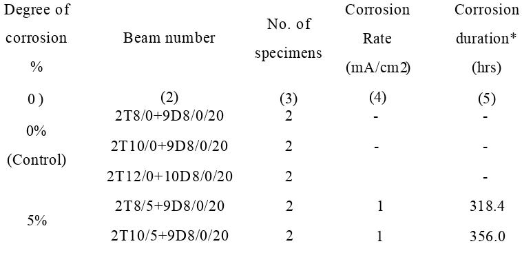
The experimental programme was carried out to provide information on the loss of strength resulting from corrosion to the main and shear reinforcement. Corrosion was induced by means of external power supplies. The test programme was divided into three series. Series I was devised to determine the residual flexural strength of reinforced concrete beams where different diameters of main (high yield) reinforcement were subjected to varying degrees of accelerated corrosion (shear strength was provided by mild steel shear reinforcement which remained unaffected by corrosion). Series II was devised to determine the residual shear strength of reinforced concrete beams where the shear (mild steel) reinforcement was subjected to varying degrees of accelerated corrosion (flexural strength was provided by high yield steel which was protected from corrosion). Finally, Series III was devised to determine the residual strength of reinforced concrete beams where both the main (high yield) and shear (mild steel) reinforcement were simultaneously corroded and the effect of this on the performance of the beam was determined. In total, 116 beams were subjected to accelerated corrosion using an impressed current imposed on the reinforcement. Each beam was loaded to failure to determine the strength loss. Four degrees of corrosion were targeted, ranging from 0% (control) to 15%, in increments of 5%.
Declaration
I hereby declare that no portion of the work referred to in this thesis has been submitted
in support of an application for another degree or qualification of this or any other
University or other institution of learning. All sources of information have been made
duly acknowledged.
Elena Hristova Hristova
A cknowledgemen
The author would like to express her sincere gratitude to Dr Finbarr J. O'Flaherty of the
Centre for Infrastructure Management, Sheffield Hallam University, for his guidance,
support and patience throughout this research project.
The author also gratefully acknowledges the contributions, sincere assistance, guidance
and supervision of Professor Pritpal S. Mangat of the Centre for Infrastructure
Management, Sheffield Hallam University.
The author wishes to express her gratitude to the Sheffield Hallam University for
funding this research project.
The author gratefully acknowledge Dr Paul Lambert of the Centre for Infrastructure
Management, Sheffield Hallam University for his important contributions to the
research.
The support provided in the laboratory by the technical staff, especially Mr. Robert
Skelton, Mr. Geoff Harwood, Mr. John Bickers, and Mr. Pete Lonsborough, of the
Construction Materials Laboratories, Sheffield Hallam University is also appreciated.
Finally, I pay my heartfelt feeling of acknowledgement to Andrew Browne for his
Table
of
Abstract... ii
Declaration...iv
Acknowledgements...v
Notation... xv
Glossary...xviii
List of Figures...xxvii
List of Tables... xxxv
Chapter 1 Introduction... 1
1.1 Introduction...1
1.2 Scope of research...2
1.3 Scope of present investigation... 5
1.4 Thesis layout... 6
Chapter 2 Literature Review... 9
2.1 Introduction...9
2.2 History of concrete...10
2.3 Properties of reinforced concrete... 10
2.4 Mechanism of concrete deterioration...11
Table o f Contents
2.5.1 Introduction...12
2.5.2 Chemical and electrochemical reactions... 12
2.5.3 General condition of corrosion, immunity and passivity...14
2.6 Corrosion initiation due to chloride attack...19
2.7 Corrosion initiation due to carbonation of concrete... 21
2.8 Bond between steel and concrete...23
2.9 Reinforced concrete beams damaged by corrosion of tensile reinforcement 29 2.9.1 Previous experimental work...29
2.9.2 Corrosion simulation by the use of electrolysis...29
2.9.3 Model of steel corrosion...34
2.10 Previous theoretical work... 36
2.11 Reinforced concrete beams damaged by corrosion of shear reinforcement 37 2.12 Conclusion...38
Chapter 3 Optimisation of the Corrosion Process... 40
3.1 Introduction...40
3.2 Accelerated corrosion... 40
3.2.1 Introduction... 40
3.2.2 Laboratory simulation...41
3.3 Methods of accelerated corrosion...45
Table o f Contents
3.4.1 Corrosion of reinforcing bars in saline solution...47
3.4.2 Corrosion of reinforcing bars in concrete...51
3.5 Design of test beams using stainless steel...52
3.5.1 Preliminary beams details...52
3.5.2 Preliminary Series 1...53
3.5.3 Performance of preliminary Series I ...58
3.6 Discussions of the preliminary results... 59
3.7 Further experimental work...60
3.7.1 Method 1...61
3.7.2 Method II...62
3.7.3 Method III...62
3.8 Concluding remarks... 63
Chapter 4 Detailed Experimental Programme...64
4.1 Introduction... 64
4.2 Objectives of investigation...64
4.3 Details of experimental programme... 65
4.4 Materials...69
4.4.1 Cem ent...69
4.4.2 Aggregates... 69
Table o f Contents
4.4.4 Steel reinforcement... 74
4.5 Potential inspection technique for steel in concrete...74
4.5.1 Reference electrode... 75
4.5.2 Digital voltmeter (ISO-TECH IDM97/97RMS)... 76
4.5.3 Power supply... 77
4.6 Instrumentation...78
4.6.1 Load measurement...78
4.6.2 Deflection measurement... 78
Chapter 5 Influence of Main Steel Corrosion on Structural Performance (Series I )... 79
5.1 Introduction...79
5.2 Objectives of test programme...80
5.3 Experimental programme...80
5.3.1 General... 80
5.3.2 Beam specimens...83
5.3.3 Process of accelerated corrosion...86
5.3.4 Test configuration and procedure... 89
5.4 Influence of corrosion on the main steel reinforcement on the flexural performance... 91
5.4.1 Beams reinforced with 2T8 main steel... 96
Table o f Contents
5.4.3 Beams reinforced with 2T12 main steel...102
5.5 Conclusions... 104
5.5.1 Conclusions from accelerated corrosions tests... 104
5.5.2 Conclusions from load tests...104
5.5.3 Conclusions from cover variations... 105
5.5.4 Conclusions from diameter variations...105
Chapter 6 Influence of Shear Reinforcement Corrosion on Structural Performance (Series II)... 107
6.1 Introduction...107
6.2 Objectives of test programme...108
6.3 Experimental programme... 108
6.3.1 Beam specimens...108
6.3.2 Process of accelerated corrosion... 112
6.3.3 Test configuration and instrumentation...113
6.4 Test results and discussion... 115
6.5 Conclusions...119
Chapter 7 Influence of Main and Shear Reinforcement Corrosion on Structural Performance (Series III)... 120
7.1 Introduction...120
7.2 Objectives of test programme...120
/ able of Contents
7.3.1 Beam specimens... 121
7.3.2 Material properties...121
7.3.3 Instrumentation...123
7.3.4 Test configuration and procedure...123
7.3.5 Process of accelerated corrosion... 124
7.4 Influence of corrosion on the flexural performance...128
Chapter 8 Experimental Results and Discussion - Series I ... (Main reinforcement corrosion)...135
8.1 Introduction...135
8.2 Aim...135
8.3 Critical overview of the test methodology...136
8.4 Structural performance of corrosion damaged beams under four point bending test... 138
8.4.1 Beam Series I reinforced with 2T8 main steel reinforcement...139
8.4.1.1 Load / Deflection...139
8.4.1.2 Residual flexural strength...145
8.4.2 Beam Series I reinforced with 2T10 main steel reinforcement... 155
8.4.2.1 Load / Deflection... 155
8.4.2.2 Residual strength... 164
8.4.3 Beam Series I reinforced with 2T12 main steel reinforcement... 169
Table o f Contents
8.4.3.2 Flexural strength... 170
8.5 Conclusions... 175
8.5.1 General...175
8.5.2 Flexure... 176
8.5.3 Load - Deflection...177
8.5.4 Further discussion...177
Chapter 9 Experimental Results and Discussion - Series II... (Shear reinforcement corrosion)... 179
9.1 Introduction... 179
9.2 Aim... 179
9.3 Structural performance of beams exhibiting shear reinforcement corrosion.... 179
9.3.1 Beam Series II reinforced with 2T8 main steel reinforcement... 184
9.3.1.1 Load - central defection relationships...184
9.3.1.2 Residual flexural strength...184
9.3.2 Beam Series II reinforced with 2T12 main steel reinforcement... 187
9.3.2.1 Load - central defection relationships...187
9.3.2.2 Residual flexural strength... 189
9.4 Final remarks...193
Chapter 10 Experimental Results and Discussion - Series III ... (Main and shear reinforcement corrosion)...195
Table of Contents
10.2 Aim... 195
10.3 Flexural testing...196
10.3.1 Load - deflection curves...198
10.3.2 Flexural strength... 202
10.4 Final remarks...208
Chapter 11 Analytical Modelling of Experimental Data...209
11.1 Introduction... 209
11.2 Current method of residual life prediction... 210
11.3 British code BS 8110 and design of concrete structures EC2...212
11.4 Analysis of a doubly reinforced rectangular section... 214
11.4.1 Design for moment of resistance... 214
11.4.2 Design for shear resistance... 216
11.5 Characteristics of reinforced concrete beam s...219
11.6 Effect of corrosion on the flexural capacity of reinforced concrete beam s 220 11.6.1 Characteristics of beam Series 1...220
11.6.2 M t(o/Mcrelationship for various degrees of corrosion... 220
11.6.3 Designing for durability... 236
11.6.4 Residual tensile moment of resistance... 241
Table o f Contents
Chapter 12 Conclusions and Recommendations...245
12.1 Introduction...245
12.2 Conclusions...245
12.2.1 Conclusions from experimental design... 245
12.2.2 Conclusions from accelerated corrosion tests...246
12.2.3 Conclusions from load tests...247
12.2.4 Performance of corroded reinforced concrete beams...248
12.2.5 Practical implications...248
12.3 Recommendations... 250
12.4 Final remarks... 250
Chapter 13 References... 252
Appendix A... 272
Notation
The great majority of the symbols listed below are essentially those used in the current
British Design Practice. Less frequently used symbols and symbols which have
different meanings in different contexts are defined where they are used.
A atomic weight of iron
Ac cross sectional area of concrete
As cross sectional area of tensile reinforcement
As cross sectional area of hanger bars
Asv total cross sectional area of shear reinforcement
a slope of M t ( C o r r ) / M c against percent of corrosion
b width of beam
bw breadth of section
(3 intercept (or M t ( C o r r / M c ratio)
c cover to main steel reinforcement
CSA cross sectional area
d effective depth
d depth from compression face to centroid of compression reinforcement
Notation
E° electrode potential under standard conditions
Ec modulus of elasticity of concrete
Es modulus of elasticity of steel
Epitting pitting potential
8cll maximum strain in concrete
ss strain in reinforcement
f c concrete strength in compression
f cu cube compressive strength of concrete
f s tensile stress in steel reinforcement
f y yield stress in tensile reinforcement
f y yield stress in compression reinforcement
fyv characteristic strength of the shear reinforcement
F Faraday’s constant
Fcc force in the concrete in compression
Fsc force in the steel in compression
(/>' diameter of the compressive steel reinforcement
i current density
I corrosion current
Mc maximum moment of resistance of the compression zone
Mt(Corr) moment of resistance of the corroded beam in the tensile zone
M design ultimate moment
Peon average failure load of control specimens in the laboratory
PuU ultimate failure load from laboratory beam tests
P design shear force due to ultimate loads
R corrosion rate
p steel ratio
sv centre to centre of spacing of shear reinforcement
5 depth of idealised compressive stress block
T time
2RT/D % degree of corrosion
(p nominal perimeter of the steel bar
v design shear stress at a cross section
vc design concrete shear stress
V ultimate shear force
x depth to neutral axis
Glossary
These definitions are not full, accurate scientific or dictionary definitions and may be
incomplete if used outside the context of the subject of corrosion of steel in concrete.
Acid
A solution that (among other things) attacks steel and other metals and reacts with
alkalis forming a neutral product and water.
Alkali
A solution that (among other things) protects steel and other metals from corrosion and
reacts with acids forming a neutral product and water.
Anode
The site of corrosion in an aqueous corrosion cell (a combination of anodes and
cathodes).
An external component introduced into a cathodic protection system to be the site of
Glossary
Carbonation
The process by which carbon dioxide (CO2) in the atmosphere reacts with water in
concrete pores to form carbonic acid which then react with the alkalis in the pores,
neutralising them. This can then lead to the corrosion of the reinforcing steel.
Cathode
The site of a charge balancing reaction in a corrosion cell.
The protected metal structure in a cathodic protection system.
Cathodic protection
A process of protecting a metal object or structure from corrosion by the installation of
sacrificial anode or impressed current system that makes the protected object a cathode
and thus resistant to corrosion.
Cathodic protection anode
A cathodic protection anode for steel in concrete can be a conductive paint or other
conductive material that will adhere to concrete, or a metal mesh or other conductive
material that can be embedded in a concrete overlay on the surface of the structure to be
Glossary
Cement (paste)
Portland cement is a mixture of alumina, silica, lime, iron oxide and magnesia ground to
a fine powder, burned in a kiln and ground again. Cement paste is the binding agent for
mortar and (Portland cement) concrete after hydration.
Chloride
The negative ion in salt, found in sea salt, de-icing salt and calcium chloride admixture
for concrete. Chloride ions promote corrosion of steel in concrete but are not used up
by the process so they can concentrate and accelerate corrosion.
Chloroaluminates
Chemical compounds formed in concrete when chlorides combine with the C3A in the
hardened cement paste. These chlorides are no longer available to cause corrosion.
Sulphate resisting cements have a low C3A content and are more prone to chloride
induced corrosion than normal Portland cement based concretes.
Concrete
Portland cement concrete is a mixture of cement, fine and coarse aggregates and water.
Glossary
Corrosion
The process by which a refined metal reverts back to its natural state by an oxidation
reaction with the non-metallic environment (e.g. oxygen and water).
Galvanic corrosion
The difference in electrochemical potential between two or more dissimilar metals in
electrical contact and in the same electrolyte causes electron flow between them. Attack
of the more noble metal or metals usually decreased, and corrosion of the more active
metal is usually increased.
Half cell
Usually a pure metal in a solution of (fixed) concentration. The half reaction of the
metal ions dissolving and reprecipitating creates a steady potential when linked to
another half cell. Two half cells make an electrochemical cell that can be a model for
corrosion. Reference half cells are connected to reinforcing steel to measure 'corrosion
potentials' that show the corrosion condition of the steel in concrete.
Impressed current cathodic protection
A method of cathodic protection that uses a power supply and an inert (or controlled
Glossary
Incipient anode
An area of steel in a corroding structure that was originally cathodic due to the action of
local anode. When the local anode is treated by patch repairing, the incipient anode is
no longer protected and starts to corrode.
Ion
An atom or molecule with electrons added or subtracted. Ionic compounds like salt
(calcium chloride) are composed of balanced ions (CaCl2=Ca2++2Cf). Some ions are
soluble (e.g. Ca , Cl , Fe ) which can be important for transport through concrete.
Ionic current
An electric current that flows as ions through an aqueous medium (e. g. concrete pore
water), as opposed to an electronic flow of electrons through a metal conductor.
iR drop
Electrical current passing through a solution of finite resistance generates a voltage.
This is superimposed on the half cell potential and must be subtracted to get accurate
readings in linear polarisation and in cathodic protection. This is most easily done by
'instant off measurements of potentials taken within a few seconds of switching off the
Glossary
Oxidation
The process of removing electrons from an atom or ion. The process:
F e ^ F e 2++2e“
Fe2+->Fe3++e~
is the oxidation of iron to its ferric (Fe2+) and ferric (Fe3+) oxidation state. Oxidation is
done by an oxidising agent, of which oxygen is only one of many.
Passivation
The process by which steel in concrete is protected from corrosion by the formation of a
passive layer due to the highly alkaline environment created by the pore water. The
passive layer is a thin lOxlO-10 m, dense layer or iron oxides and hydroxides with some
mineral content, that is initially formed as bare steel is exposed to oxygen and water, but
then protects the steel from further corrosion as it is too dense to allow the water and
oxygen to reach the steel and continue the oxidation process.
pH
A measure of acidity and alkalinity based on the fact that the concentration of hydrogen
ions [H+] (acidity) times hydroxyl ions [OFT] (alkalinity) is 10 14 moles/1 in aqueous
solutions:
[H+] [OH ] = lxl0~14
PH = -log[H+]
Glossary
i.e. a strong acid has pH=l (or less), a strong alkali has pH=14 (or more), a neutral
solution has pH=7. Concrete has a pH of 12 to 13. Steel corrodes at pH 10 to 11.
Reduction
Chemically this is the reverse of oxidation. The incorporation of electrons into a non-
metal oxidising agent when a metal is oxidised. When oxygen (O2) oxidised iron (Fe)
to Fe it receives the electrons that the iron gives up and is itself reduced:
0 2+4e'->202~
2e+ H 20 + i 0 2-»20H~
are reduction reactions.
Pore (water)
Concrete contains microscopic pores. These contain alkaline oxides and hydroxides of
sodium, potassium and calcium. Water will move in and out of the concrete saturating,
part fdling and drying out the pores according to the external environments. The
alkaline pore water sustains the passive layer if not attacked by carbonation or chlorides.
Reference electrode
Glossary
Reinforced concrete
Concrete containing a network of reinforcing steel bars to make a composite material
that is strong in tension as well as in compression. Smaller volumes of material can
therefore be used to make beams, bridge spans, etc. compared with unreinforced
concrete, brick or masonry.
Rust
The corrosion product of iron and steel in normal atmospheric conditions. Chemically
it is hydrated ferric oxide FeiCb.f^O. It has a volume several times that of the iron that
was consumed to produce it.
Sacrificial anode cathodic protection
A system of cathodic protection that uses a more easily corroded metal such as zinc,
aluminium or magnesium to protect a steel from corrosion. No power supply is
required, but the anode is consumed.
Steel
Glossary
Titanium mesh anode
A type of impressed current anode consisting of an expanded titanium mesh coated by a
corrosion resistant film of mixed metal oxides. After being fixed to the concrete surface
List of Figures
Figure 1.1 The collapse of the Berlin Congress Hall, 1980 ... 3
Figure 1.2 Collapse of a salt damaged parking garage in Minnesota, 1984... 3
Figure 1.3 Collapse of a car park in Wolverhampton, UK, in 1997... 4
Figure 1.4 Collapse of a footbridge in North Carolina, USA, in 2000... 4
Figure 2.1 Electrochemical equilibria of the iron - water system ... 14
Figure 2.2 Cartoon diagram for iron from Christmas message from Pourbaix 42.... 16
Figure 3.1 Accelerated corrosion apparatus... 41
Figure 3.2 Reinforcement bars under corrosion...48
Figure 3.3 Corrosion of the reinforcement in small concrete prisms... 52
Figure 3.4 Preliminary Series I: a.) elevation; b.) cross section X -X ...54
Figure 3.5 Accelerated corrosion of reinforcing steel in the laboratory...56
Figure 3.6 Preliminary beam under test...57
List o f Figures
Figure 3.8 Stainless steel stirrups exhibiting pitting corrosion... 61
Figure 4.1 Grading curve for fine aggregate...71
Figure 4.2 Grading curve for coarse aggregate... 72
Figure 4.3 Monitoring of the accelerating corrosion technique... 75
Figure 4.4 Standard Calomel reference electrode... 76
Figure 4.5 Digital voltmeter...77
Figure 5.1 Geometry of the beam Series I used for the design...84
Figure 5.2 Reinforced concrete beams undergoing main reinforcement corrosion...
...87
Figure 5.3 Iron oxide formation on the beams after corrosion...8 8
Figure 5.4 Loading configuration and instrumentation of a test beam... 90
Figure 5.5 Reinforcement cage after corrosion... 90
Figure 5.6 Beam specimens electrically connected in series...95
Figure 6.1 Geometry of the beam Series II used for the design...109
Figure 6.2 Electrical connections between the shear reinforcement and the power
List o f Figures
Figure 6.3 Reinforcing cage used for beam Series II...111
Figure 6.4 Shear reinforcement corrosion...113
Figure 6.5 Beam in the loading rig during testing...114
Figure 7.1 Geometry of the beam Series III used for the design... 122
Figure 7.2 Exposed main and shear reinforcement...124
Figure 7.3 Transformer Rectifier (TR)...126
Figure 7.4 Precision linear power supplies... 127
Figure 7.5 Deteriorated reinforced concrete beam exhibiting both main and shear
reinforcement corrosion under te st... 129
Figure 7.6 Deteriorated main reinforcement bars after corrosion...130
Figure 7.7 Shear reinforcement with most severe corrosion...131
Figure 8.1 Average load - deflection curves of corroded reinforced concrete beams
of Series I under four point bending test... 140
Figure 8.2 Average load - deflection curves of corroded reinforced concrete beams
of Series I under four point bending test...141
Figure 8.3 Average load - deflection curves of corroded reinforced concrete beams
List oj Figures
Figure 8.4 Relationship between stiffness and degree of corrosion for beam
designed with 2T8...146
Figure 8.5 Relationship between P uit / Pcon and degree of corrosion for beam
designed with 2T8 and 26 mm cover to main steel...148
Figure 8 . 6 Relationship between P uit / P COn and degree of corrosion for beam
designed with 2T8 and 36 mm cover to main steel...149
Figure 8.7 Relationship between Puit / PCOn and degree of corrosion for beam
designed with 2T8 and 56 mm cover to main.steel...150
Figure 8 . 8 (a) Control beam crack pattern at ultimate load...152
Figure 8 . 8 (b) Beam 2T8/18.45+10D6/0/20 crack pattern at ultimate load level.... 152
Figure 8 . 8 (c) Beam 2T8/17.76+10D6/0/30 crack pattern at ultimate load level.... 153
Figure 8 . 8 (d) Beam 2T8/16.35+12D6/0/50 crack pattern at ultimate load level.... 153
Figure 8.9 Average load - deflection curves of corroded reinforced concrete beams
of Series I under four point bending test... 156
Figure 8.10 Average load - deflection curves of corroded reinforced concrete beams
of Series I under four point bending test... 157
Figure 8.11 Average load - deflection curves of corroded reinforced concrete beams
List o f Figures
Figure 8.12 Relationship between stiffness and degree of corrosion for beam
designed with 2T1 0...161
Figure 8.13 (a) Beam 2T10/7.5+10D6/0/20 crack pattern at ultimate load level... 162
Figure 8.13 (b) Beam 2T10/6.7+10D6/0/30 crack pattern at ultimate load level.. 163
Figure 8.13 (c) Beam 2T10/6.1+12D6/0/50 crack pattern at ultimate load level...163
Figure 8.14 Relationship between P uit / PCOn and degree of corrosion for beam
designed with 2T10 and 26 mm cover to main steel... 165
Figure 8.15 Relationship between Puit / Pcon and degree of corrosion for beam
designed with 2T10 and 36 mm cover to main steel...166
Figure 8.16 Relationship between Puit / P con and degree of corrosion for beam
designed with 2T10 and 56 mm cover to main steel...167
Figure 8.17 Beam 2T12/5.9/50 crack pattern at ultimate load level...169
Figure 8.18 Average load - deflection curves of corroded reinforced concrete beams
of Series I under four point bending test... 171
Figure 8.19 Relationship between stiffness and degree of corrosion for beam
designed with 2T1 2... 172
Figure 8.20 Relationship between P uit / PCOn and degree of corrosion for beam
List o f Figures
Figure 9.1 Beam 2T8/0+12D6/23.2/50 crack pattern at ultimate load level...182
Figure 9.2 Beam 2T12/0+12D6/6.1/50 crack pattern at ultimate load level... 183
Figure 9.3 Load - deflection curves of corroded concrete beams of Series II under
four point bending te st...185
Figure 9.4 Relationship between stiffness and shear reinforcement corrosion 186
Figure 9.5 Relationship between Puit / Pcon and degree of corrosion... 188
Figure 9.6 Load - deflection curves of corroded concrete beams of Series II under
four point bending te st...190
Figure 9.7 Relationship between stiffness and shear reinforcement corrosion...191
Figure 9.8 Relationship between P U|t / PCOn and degree of corrosion for beam
designed with 2T12 and 50 mm cover...192
Figure 10.1 Load - deflection curves of corroded concrete beams of Series III under
four point bending te st...199
Figure 10.2 Relationship between stiffness and main reinforcement corrosion...200
Figure 10.3 Relationship between stiffness and shear reinforcement corrosion...201
Figure 10.4 Relationship between stiffness and simultaneous main and shear
List o f Figures
Figure 10.5 Beam 2T8/8.8/50+12D6/9.1 crack pattern at ultimate load level 204
Figure 10.6 Beam 2T8/25.7/50+12D6/27.6 crack pattern at ultimate load level 204
Figure 10.7 The effect of corrosion degree on the flexural load capacity of corrosion
damaged reinforced concrete beams... 205
Figure 10.8 The effect of corrosion degree on the flexural load capacity of corrosion
damaged reinforced concrete beams... 206
Figure 11.1 (a) EC2 stress block 14 8... 213
Figure 11.1 (b) BS 8110 stress block 1 4 8 )1 4 9...213
Figure 11.2 Cross sectional area of reinforced concrete beams used in the analysis....
... 215
Figure 11.3 Schematic representation of stress due to external loading... 218
Figure 11.4 Effect of corrosion on the Mt(c0rr/Mc ratio for 2T8/Corr%+10D6/0/20
beams...224
Figure 11.5 Effect of corrosion on the Mt(corr/Mc ratio for 2T8/Corr%+10D6/0/30
beams...225
Figure 11.6 Effect of corrosion on the Mt(Corr/Mc ratio for 2T8/Corr%+12D6/0/50
List o f Figures
Figure 11.7 Effect of corrosion on the M t ( C o r r / M c ratio for 2T10/Corr%+10D6/0/20
beams... 227
Figure 11.8
Figure 11.9
Figure 11.10
Figure 11.11
Figure 11.12
Figure 11.13
Figure 11.14
Figure 11.15
Figure 11.16
Effect of corrosion on the M t ( c 0 r r / M c ratio for 2T10/Corr%+10D6/0/30
beams... 228
Effect of corrosion on the M t ( c o rr / M c ratio for 2T10/Corr%+12D6/0/50
beams... 229
Effect of corrosion on the M t ( c 0 r r / M c ratio for 2T12/Corr%+24D 6/0/50
beams... 230
Summary of the effect of corrosion on the M t ( C o r r / M c ratio for beam
Series 1... 231
Effect of corrosion on the M t ( C o r r / M c ratio for
2T8/Corr%+12D6/Corr%/50 (beam Series III shear reinforcement
corrosion < 5%)... 232
Comparison with other researchers... 234
Effect of a on the M t( o / M cratio...237
Effect of % Reinforcement on the M t( o / M cratio...239
List of Tables
Table 2.1 Summary of experimental tests on corroded beams 8 3...33
Table 3.1 Active and passive condition of steel rebar...46
Table 3.2 Reduction in reinforcing bar diameter...49
Table 3.3 Preliminary test programme... 55
Table 3.4 Experimental program for preliminary beam Series 1...59
Table 4.1 Experimental Programme...6 6
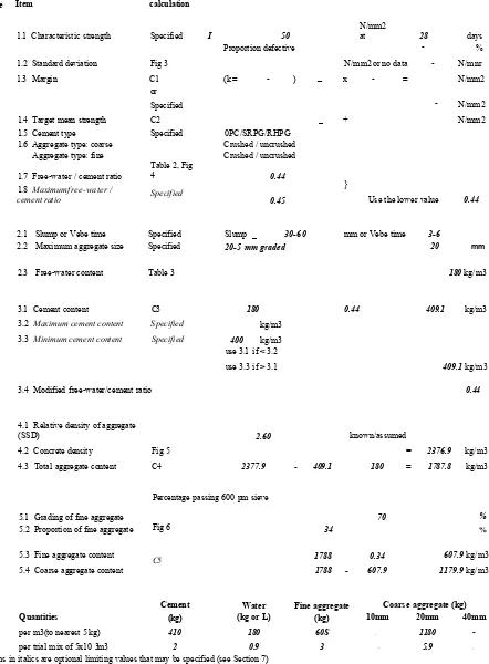
Table 4.2 Concrete mix design form...6 8
Table 4.3 Chemical composition of Portland cement by Castle Cement Ltd...70
Table 5.1 Beam Series I - Corrosion details and load behaviour of beams with main
reinforcement (2T8) corrosion...92
Table 5.2 Beam Series I - Corrosion details and load behaviour of beams with main
reinforcement (2T10) corrosion...98
Table 5.3 Beam Series I - Corrosion details and load behaviour of beams with main
List o f Tables
Table 6.1 Beam Series II - Corrosion details and load behaviour of beams with shear
reinforcement corrosion (2T8)...116
Table 6.2 Beam Series II - Corrosion details and load behaviour of beams with shear
reinforcement corrosion (2T12)...117
Table 7.1 Beam Series III - Corrosion details and load behaviour of beams with main
and shear reinforcement corrosion... 132
Table 8.1 Beam Series I (2T8/Corr%) test results... 143
Table 8.2 Comparison of residual strength at different covers and degrees of
corrosion...151
Table 8.3 Beam Series I (2T10/Corr%) test results... 159
Table 8.4 Comparison of residual strength at different covers and degrees of
corrosion...168
Table 8.5 Beam Series I (2T12/Corr%) test results...173
Table 9.1 Beam Series II (2T8/0+12D6/Corr%/50) test results... 181
Table 9.2 Beam Series II (2T12/0+12D6/Corr%/50) test results...181
Table 10.1 Beam Series III (2T8/Corr %+12D6/Corr %/50) test results... 197
List o f Tables
Table 11.2 Beams properties...222
Table 11.3 Results of regression analysis... 233
Chapter 1
Introduction
1.1 Introduction
The development of reinforced concrete by French engineers in the middle of the 19
century was one of the major advances in the history of construction Most of today's
concrete construction relies on the composite interaction of concrete and steel, which is
aided by the near equivalence of their thermal expansion characteristics. In general,
reinforced concrete has proved to be a highly successful material in terms of structural
performance. However, there have been numerous examples of the durability problems
arising from the corrosion of reinforcement in concrete structures, mostly due to poor
quality concrete, poor design and workmanship, inadequate cover to reinforcement,
chlorides in the concrete or combinations of these. These have led to various forms of
corrosion induced damage such as cracking and spalling, resulting in reductions in
structural capacity.
When steel reinforcement corrodes, corrosion products generate tensile stresses in the
concrete. Concrete is very strong in compression but weak in tension, the tensile
strength being only about 10 percent of the compressive strength. Therefore tensile
cracks are readily nucleated and propagated as a result3. The development of corrosion
products along the bar surface may affect the failure mode and ultimate strength of
c,napiar i Introduction
confinement caused by an opening of longitudinal cracks along the reinforcement and,
secondly, due to significant changes at the steel-concrete interface caused by changes in
the surface conditions of the reinforcing steel. The changes in the surface conditions
due to corrosion are characterised initially by changes in the roughness of the surface,
then, by development of less firm adherent interstitial layers of corrosion products
between concrete and steel and, eventually, by local damage in terms of heavy pitting
and degradation in the profile of the bar ribs 4.
1.2 Scope of research
Reinforcement corrosion in concrete structures is the biggest durability problem facing
the UK at present. In the press release, the Building Research Establishment estimated
the direct cost of reinforcement corrosion to the UK economy to be around £550M per
year 5 since repair and maintenance is required to increase the service life of the
structure 6’7’8’9.
Corrosion of reinforcing bars is one of the main causes which induces deterioration of
concrete beams, thus reducing their residual service life. For example, the collapse of
the Berlin Congress Hall in 1980 (Figure 1.1) 10 and a parking garage in Minnesota,
USA in 1984 (Figure 1.2) 10 are examples of spectacular failures due to a reduction in
residual strength due to corrosion of the steel reinforcement.
Furthermore, the sudden collapse of part of a car park in Wolverhampton, UK in 1997,
which was built using the American developed lift slab technique, Figure 1.3 11 and a
footbridge in North Carolina, USA in 2000, Figure 1.4, are also examples of problems
unapier i Introduction
/ : . . . '••• • ;
Figure 1.1 The collapse of the Berlin Congress Hall, 1980
v^ riu p icr i Introduction
T
Figure 1.3 Collapse of a car park in Wolverhampton, UK, in 1997
Introduction
Figure 1.4 after collapse, high levels of calcium chloride were found in grout used in the
construction 12.
Clearly, corrosion of the reinforcing bars is one of the main causes of deterioration of
reinforced concrete beams. Corrosion affects both the main and shear reinforcement,
therefore it is important to know the effect this will have on the residual strength of the
member. Consequently, catastrophic failure such as those mentioned earlier can be
controlled through better knowledge of the flexural and shear capacities of deteriorating
members.
1.3 Scope of present investigation
This study contributes to understanding the effect of reinforcement corrosion on the
behaviour of reinforced concrete structures. Currently, much research is focused on
corrosion in reinforced concrete members. However, the problems associated with the
residual strength of corroded reinforced concrete beams have not been fully addressed.
To date extensive research has been undertaken to assess flexural strength of corroded
reinforced concrete beams, but to date, there is no evidence of research being conducted
on the shear strength. Furthermore, the influence of both main and shear reinforcement
corrosion occurring concurrently also needs to be investigated to determine its effect on
the performance of the member. Therefore, the aim of this research was to determine
the residual strength of corroded reinforced concrete beams when the main and shear
reinforcement are subjected to varying degrees of corrosion. Analytical models are
developed to predict the behaviour of deteriorated reinforced concrete elements. This
will provide a better understanding of the performance of such beams in practice.
l napter i Introduction
• investigate the chemical processes involved in corrosion of steel reinforcement;
• determine the techniques involved in accelerating corrosion in reinforced concrete
members in the laboratory;
• investigate the residual strength of reinforced concrete beams subjected to
different percentages of main steel corrosion;
• investigate the residual strength of reinforced concrete beams subjected to
different percentages of shear reinforcement corrosion;
• investigate the residual strength of reinforced concrete beams subjected to
different percentages of both main and shear reinforcement corrosion;
• develop analytical models to predict the behaviour of deteriorated reinforced
concrete beams on the basis of the laboratory experiments.
1.4 Thesis layout
The thesis attempts to bring together results which will be used to assist the bridge
engineer in the assessment of reinforced concrete structures exhibiting reinforcement
corrosion.
This thesis is divided into thirteen chapters. An introduction to the thesis is given in
Chapter 1.
Chapter 2 includes a brief discussion of the principles of metallic corrosion and the
basic deterioration mechanisms in reinforced concrete structures. Chapter 3, presents
cnapier i Introduction
The detailed experimental programme, including materials used and experimental
procedures and techniques, is described in Chapter 4.
Chapter 5 presents experimental results obtained from the first test series. Included is
research on the influence of corrosion on the main reinforcement of simply supported
beams (shear strength was provided by mild steel links which remained unaffected by
corrosion). The degree of under reinforcement was varied (8, 10 and 12 mm diameter
main steel was used) and each was subjected to differing percentage of corrosion
(0 - 15% in 5% increments).
Chapter 6 presents results on the second test series. The shear reinforcement was
subjected to varying percentage of corrosion (0 - 15% in 5% increments) in order to
determine its affect on the shear capacity. The main steel remained unaffected
throughout.
In Chapter 7, the experimental results obtained from the third test series are presented.
The residual strength of reinforced concrete beams is determined when the main and
shear reinforcement are simultaneously subjected to varying degrees of reinforcement
corrosion (0 - 15% in 5% increments).
Chapters 8, 9 and 10 presents the experimental results obtained from three series
(Series I, Series II and Series III respectively) of tests, the analysis of test data,
interpretation and discussion on the results.
Analytical models are derived in Chapter 11 which predict the residual strength of
corroded reinforced concrete beams.
Chapter 12 presents the main conclusions from the study and recommendations are
Appendix A summarises the design data. The publications to date arising from the
Chapter
Literature Review
2.1 Introduction
The increase in the scale of the problem of deterioration of reinforced concrete members
can be illustrated by the number of publications concerned with the science of
reinforced concrete decay and its mechanism. However, it is not the intention of the
present study to deal with causes, remedies or mechanisms of corrosion of the
embedded reinforcing steel or the subsequent deterioration of the concrete. The main
aim is to determine the structural performance of these deteriorated members.
In the light of the objectives stated in Chapter 1, the survey of previous research and
related documents and reports presented herein has been confined to the specific area of
structural integrity assessment of corrosion damaged, flexural members. In the present
chapter, two areas of previous research work relevant to the present study are examined
and discussed. These comprise:
• Theoretical, numerical and experimental work done specifically on the
assessment of strength and characteristic behaviour of reinforced concrete beams
damaged by the corrosion of tensile reinforcement;
• Similar work done on reinforced concrete beams where the tensile reinforcement
is completely debonded from the adjoining concrete and shear reinforcement is
napier z Literature Review
2.2 History of concrete
The development of concrete as a construction material dates back several thousand
years to the days of ancient Egyptians, the Greeks and the Romans. These early
concrete compositions were based on lime, although the Romans are known for their
development of pozzolanic cement and lightweight concrete 13. Apart from brief
revivals over the years, there was little further development until the eighteen century
when the industrial revolution evolved. Later in the nineteen century, the technique of
reinforced concrete was introduced. The credit for introduction of steel as a
requirement is variously attributed to Joseph Aspdin 1824, William Wilkinson 1854,
Lambot in 1855 for ferrocement boats, to Monier in 1867 and to Hennebique in 1897
who built the first reinforced concrete frame building in Britain at Weaver’s Mill,
Swansea. Notable steps forward in this century have been introduction of prestressed
concrete by Freyssinet in the 1940s, the extensive use of reinforced concrete during
World War II, the rapid post-war concrete building expansion prompted by shortages of
steel, the motorway building boom of the 1960s involving concrete pavements and
bridges, and most recently, the contribution of structural concrete to modern offshore
structures 14.
2.3 Properties of reinforced concrete
Concrete may be described as a graded range of stone aggregate particles bound
together by a hardened cement paste 15. The main chemical constituents of Portland
cements are lime (CaO), which composes 60% - 67% of the total, silica (SiCh), which
L,napter z Literature Review
iron oxide (Fe2 0 3), magnesia (MgO), sulphur trioxide (S 03) and sodium (Na2 0) and
potassium (K2O) oxides 16. Concrete strength is derived from the hydration of the
cement by water. The cement constituents progressively crystallize to form a gel or
paste which surrounds the aggregate particles and binds them together. For any given
condition of test, the strength of a workable concrete mix is dependent on a number of
parameters, mainly the cement content and the water/cement ratio.
The tensile strength of concrete is only about 10 percent of the compressive strength 13.
Therefore, reinforcement is designed to carry these tensile forces, which are transferred
by bond between the interfaces of the two materials 17’18,19.
Reinforced concrete is a strong durable building material that can be formed into many
varied shapes and sizes. Its utility and versatility is achieved by combining the best of
features of concrete and steel. The materials are more or less complimentary; the steel
is able to provide the tensile strength and probably some of the shear strength while the
concrete, strong in compression, protects the steel to give durability and fire
resistance 14.
2.4 Mechanism of concrete deterioration
Deterioration of the concrete is rarely due to one isolated cause, and concrete can suffer
from various mechanisms of deterioration 13. Environmental processes may cause salts,
oxygen, moisture or carbon dioxide to penetrate the concrete cover and eventually lead on 01 00 ot 0/i
to corrosion of embedded steel reinforcement ’ ’ ’ ’ .A s the steel corrodes, apart
from the resulting loss in its cross sectional area, the corrosion products expand in
OS 96 97 9ft 90
volume causing cracking ’ ’ ’ ’ , rust staining and spalling of the concrete
e,napier / Literature Review
service life of reinforced concrete is well documented 10, costing the UK an estimated
£550m per annum. The problem is also widespread in overseas, i.e. it has been reported
that corrosion costs in the USA alone are estimated to be close to $300 billion a year, or
approximately 3.2% of the USA gross domestic product 30. Over the past 25 years, a
number of methods for assessing the state of corrosion of reinforcing steel have been
under development, but to date difficulties in accuracy and reliability are still present31.
Consequently a reliable and accurate corrosion tool that can be used to survey
reinforced concrete structures is required.
2.5 Principles of corrosion
2.5.1 Introduction
The word corrosion means the destruction of a material under the chemical or
electrochemical action of the surrounding environment 32,33,34. It is well known that
iron, unless adequately protected, corrodes easily and is transformed into rust.
Corrosion phenomena are very complex ’ . Corrosion obeys the thermodynamic
laws; metals tend to return to the state in which they are found in nature. Metals
gradually destroy under the action of water, air and other atmospheric agents. They
corrode and transform themselves into substances similar to the mineral ores from
which they were originally extracted 22,37.
2.5.2 Chemical and electrochemical reactions
The lack of success in applying chemical thermodynamics to corrosion is principally
^napier z Literature Keview
only chemical but also electrochemical, in which the moist concrete forms the
O O Q Q
electrolyte, the possible electrochemical reactions taking place on embedded steel ’ .
A chemical reaction is a reaction in which only chemical bodies participate (neutral
molecules or positively and negatively charged ions).
dissolution of water vapour 2H2O = 2H2 + 0 2
electrolytic dissolution of liquid water H20 = H+ + OH“
precipitation of ferrous hydroxide Fe++ + 20H ” = Fe(OH)2
corrosion of iron with evolution of hydrogen Fe + 2H+ = Fe++ + H2
An electrochemical reaction is a reaction in which both chemical and free electric
charges take part (e.g. negative electrons dissolved in metallic electrode). Such
reactions are oxidations if they proceed in the direction which corresponds to the
liberation of negative charge; they are reductions if they proceed in the direction
corresponding to the absorption of negative charge.
oxidation of hydrogen gas into hydrogen ions H2 -> 2H+ + 2e^
reduction of oxygen gas into hydroxide ions O2 + 41^0 + 4e“ -» 40FT
oxidation of iron to ferrous ions Fe —» Fe++ + 2e^
oxidation of ferrous ions to ferric ions Fe -» Fe +e
When emphasizing the dependence of pH and potential, it is useful to write the
equilibrium of precipitation of ferrous hydroxide as Fe++ + 2H2O = Fe(0 H) 2 + 2H+,
where pH measures the effect of H+ ions, the electrode potential measures the effect of
^napier z Literature Review
2.5.3 General condition of corrosion, immunity and passivity
It is convenient to use a graphical means to study such a complex phenomena (see
Figure 2.1), thermodynamically represented by a simplified Pourbouix diagram. Then
^ s h e
1.2
0.8 FeC
Ee(OH) 0.4
0
0.4
FeCI
0.8
1.2
2
4 6 80
10
Figure 2.1 Electrochemical equilibria of the iron - water system 42
all the competing and simultaneous reactions, both chemical and electrochemical, can
be studied. It has been possible to establish one such graphical method with the use of
diagrams of electrochemical equilibria, drawn as a function of pH (abscissa) and
electrode potential (ordinate). The left portion of these diagrams represents acid media
and the right portion alkaline media; the top portion represents oxidizing media and the
[image:53.618.169.420.126.462.2]Chapter / Literature Review
circumstances under which the water may be reduced with the evolution of hydrogen
under pressure of 1 atmosphere; the region above the dotted line (b) represents the
circumstances under which water may be oxidized with evolution of oxygen; and the
region between the two lines (a) and (b) represents the circumstances in which both this
reduction and oxidation are impossible. Water then is thermodynamically stable and
this region represents the region of thermodynamic stability of water under 1 atm
pressure.
Depending on the actual conditions of the pH and electrode potential, Figure 2.1 shows
that the oxidation of iron may give rise to soluble products - green ferrous ions, Fe++,
yellow ferric ions, Fe+++, and green dihypoferrite ions, F e02H“ - or to insoluble
products - white ferrous hydroxide Fe(OH) 2 (unstable relative to black magnetite,
Fe3C>4) and brown ferric oxide Fe2(>3, which may be variously hydrated and is the main
constituent of rust. Iron is corroding in the presence of an iron free solution when the
quantity of iron that this solution may dissolve is greater than a given low value (e.g.,
1(T6 g-atoms / litter or 0.056 ppm), and conversely iron may be rendered passive if it
becomes covered by a protective insoluble oxide of hydroxide (e.g., Fe2C>3). Then the
lines which are drawn in Figure 2.1 corresponding to a solubility of metal and its oxide
equal to 10 6 delineate various regions or areas. There are two areas where corrosion is
possible (areas of corrosion), and area where corrosion is impossible (area of immunity
or cathodic protection), and an area where passivation is possible (area of passivation),
Figure 2.2. This assumes that the insoluble products, Fe2 0 3 and Fe3C>4, are sufficiently
adherent and impermeable that corrosion of the underlying metal is essentially stifled
K^riufJier z Literature Keview
PASSiVATiON
.MOMiTE
Figure 2.2 Cartoon diagram for iron from Christmas message from Pourbaix 42
Diagram of electrochemical equilibria of the iron - water system at 25°C may be
deduced by assuming that passivation results either from the formation of a film of
Fe20 3 or from the formation of a films of Fe2C>3 and Fe3C>4 10,43. The region of stability
of iron is entirely below the region of stability of water under atmospheric pressure.
In other words, regardless of the pH of the solution, metallic iron and water are not
simultaneously thermodynamically stable at 25°C under a pressure of 1 atm. The
simultaneous stability of iron in the presence of water at 25°C is only attained at
pressures high enough to depress the equilibrium potential of the H20 - H2 system
(represented for 1 atm by line (a), in Figure 2.1) below the equilibrium potential of the
y^nupiar z Literature Review
pressures greater or equal to 750 atm. At lower pressure iron always tends, if it is not
passivated, to be corroded with reduction of water and evolution of hydrogen. This
corrosion of iron gives rise to the dissolution of metal mainly with the formation of
green ferrous ions Fe++ (reaction 1) or dihypoferrite ions Fe02H_ (reaction 2) which are
also green, depending on whether the pH is greater or less than 10.6. At values of pH
below about 6 to 7, these ions may change to black magnetic iron oxide, or magnetite
Fe3C>4 (reaction 3) or into white ferrous hydroxide Fe(OH)2 (reaction 4). Because area
of stability of magnetite, Fe3C>4, Fe(OH)2 will be thermodynamically unstable with
respect to Fe3C>4 and will tend to transform to this substance (reaction 5). In the
presence of oxygen ferrous ions and magnetite may be oxidized to ferric oxide Fe2 0 3
(or ferric hydroxide Fe(OH) 3 (reaction 6 and 7).
Reaction 1 Fe -> Fe’1-1’ + 2e“
2H+ + 2e_ -» H2
Fe + 2H+ Fe++ + H2
Reaction 2 Fe + 2H20 -> Fe02H“ + 3H+ + 2e~
2H+ + 2e_ -» H2
Fe + 2H20 -> Fe02H~ + H+ + H2
Reaction 3 3Fe++ + 4H20 —> Fe3 0 4 + 8H+ + 2e
2H+ + 2e“ -> H2
c /2apter z Literature Review
Reaction 4 Fe++ + 2H20 -» Fe(OH)2 + 2H4
Reaction 5 3Fe(OH) 2 ->• Fe304 + 2H20 + 2H+ + 2e~
2H+ + 2e“ -> H2
3Fe(OH)2 -> Fe30 4 + 2H20 + H2
Reaction 6 4Fe++ + 12FI20 -> 4Fe(OH) 3 + 12H+ + 4e~
02 + 4H+ + 4e~ -> 2H20
4Fe++ + 0 2 + 10H2O 4Fe(OH)3 + 8Hh
Reaction 7 4Fe3C>4 + 2H2O —> 6Fe2 0 3 + 4H+ + 4e
02 + 4H+ + 4e" -> 2H20
4 F e 3 0 4 + O 2 - > 6Fe2C>3
Corrosion of iron is possible in two regions, roughly triangular in shape, which
correspond to the dissolution of metal with the formation of ferrous and dihydroferrite
ions, respectively. Such corrosion by dissolution will affect the entire metal surface and
so will be of a general nature.
The metal may be protected against this corrosion by lowering its electrode potential to
the region of immunity (in which case there will be cathodic protection, obtainable by
intervention of a reducing action) or by raising its electrode potential into the region of
passivation (in which case there will be protection by passivation, obtained by
L,napier / L ,u e ru iu r <c i w v i e w
In the case of protection by immunity, the metal will be thermodynamically stable and,
as a result, will not corrode; it will possess a truly metallic surface. Since water is not
stable under the conditions of electrode potential and pH corresponding to this state of
immunity, this protection will only be achieved by continuous consumption of external
energy which causes hydrogen evolution on the iron.
Passivity is defined as a state of metal in which the rate of ionization in a given
condition is much less than the rate at a less oxidizing condition. The mechanism of the
passive film formation and its growth on the steel in concrete is not exactly the same as
that of the steel directly in alkaline solution. However, the appreciation of the passivity
of steel directly in an alkaline solution is important for understanding the passivity of
steel in concrete which has highly alkaline pore solution. In this case of protection by
passivation the metal itself will not be stable, but will be covered by a stable oxide film
(Fe3 0 4 or Fe2C>3 according to the conditions of potential or pH). The protection will be
perfect or imperfect depending on whether or not this film perfectly shields the metal
from contact with the solution. In the case of imperfect position, corrosion only affects
the weak points of the passive film and therefore has a localized character. Water being
stable under the conditions of electrode potential and pH which correspond to the state
of passivation 10, this state will be attained without consumption of external energy; the
solution needs only be sufficiently oxidizing for the electrode potential of the metal to
be maintained permanently in the passivation region.
2.6 Corrosion initiation due to chloride attack
It is well documented that the intrusion of chloride ions in reinforced concrete can cause
•r- , • . * 3, 44, 45, 46, 47, 48, 49, 50, 51, 52, 53, 54, 55, 56
cnapier z Literature Review
Chloride ions may be introduced into concrete in a variety of ways, such as during
manufacturing as intentional or accidental intrusion or by penetration from an external
source. In concrete, chloride ions may be present in various forms such as:
• Free chloride ions in pore solution;
• Chloride loosely bonded to hydrates of calcium silicate;
• Chloride strongly bonded to hydrates of calcium aluminates.
It is principally only the free chloride ions that influence the corrosion process. There
is, however, a general lack of information about the level of chloride likely to remain
un-combined for a long period in the solution phase.
The concept of critical chloride level or corrosion threshold for steel in concrete has
been suggested by a number of investigators using variety of experimental techniques.
There is some evidence that the hydroxyl ion concentration of concrete has an influence
on the critical chloride level 37,58,59. The Building Research Establishment categorise
the chloride ion content (% by weight of cement) in terms of corrosion risk as follows:
• Less than 0.4% - low risk;
• Between 0.4 - 1.0% - medium risk;
• More than 1 % - high risk.
It is highly recognised that chloride has negligible influence on the pH of concrete. The
enhancement of the C3A content reduces the chloride content within the cement but the
optimum level has not been established. The chloride complex with C3A, however,
becomes unstable when carbonation occurs which tends to liberate chloride ions. On
^riufjier z Literature Keview
factor in relation to corrosion risk. Investigations have confirmed that diffusion is
strongly influenced by cement type and fineness, the ion exchange capacity of the
system, and the curing of the concrete surface. The effect of water/cement ratio is only
limited to a surface layer of the concrete and to short duration of chloride exposure. It
was reported 60 that the high cement content and low water/cement ratio of the mixes do
not present a barrier to the penetration of chlorides into concrete.
The precise mechanism by which depassivation occurs is still a subject of contention.
Either the chloride ions convert the insoluble iron oxides to soluble ion chlorides which
diffuse away and destroy the passive film or ions are absorbed on the metal surface and
promote the hydration and dissolution of metal ions.
2.7 Corrosion initiation due to carbonation of concrete
Carbonation is the process whereby concrete is attacked by atmospheric carbon dioxide.
More specifically, carbonation is a chemical reaction between one of the main hydration
products of cement in concrete, calcium hydroxide, and carbon dioxide from the
atmosphere. A simplified equation for the reaction can be given as:
Ca(OH)2 + C 0 2 -> CaC03 + H20
Essentially, carbonation begins at the outer surface of a concrete element and progresses
inwards. The rate of progress of this carbonation front is affected by many factors,
some of which are external to the concrete and some internal.
Although the reaction in the carbonation process is a chemical one, the rate at which this
L,napter / Literature Review
of diffusion of carbon dioxide into any concrete pores which afford a continuous
passage from the external atmosphere.
In pure air, carbon dioxide makes up approximately 0.03% by volume compared with
about 20.5% by volume of oxygen. Since carbonation is a diffusion controlled process,
it may be assumed that the rate of carbonation will vary in direct proportion to the
approximate square root of the concentration of carbon dioxide in the air.
The mechanism which relates the relative humidity in the atmosphere to the rate of
carbonation is not clear. It is, however, generally accepted that at very high relative
humidity, the rate of carbonation decreases significantly 61. The mechanism put forward
for this decrease is the blocking of pores in the concrete by water which has condensed
within them. It may be thought that the dry atmosphere would allow the rapid
evaporation of water produced by the carbonation reaction, thereby promoting rapid
carbonation. However, this evaporation would depend on the temperature. An increase
in the ambient temperature will allow the reaction rate of the carbonation process to
increase and will also increase the rate of diffusion of the carbon dioxide through the
concrete.
Diffusion is the process by which matter is transported from one part of a system to
another as a result of random molecular motions leading to a more uniform
concentration of those molecules. The diffusion of carbon dioxide into concrete