Microstructure and Electrochemical Performance of
Fully Ceramic Composite Anodes for SOFCs
Harald Schlegl
This thesis is submitted for the degree of PhD
at the
University of St Andrews
1. Candidate’s declarations:
I, Harald Schlegl hereby certify that this thesis, which is approximately 41500 words in length, has been written by me, and that it is the record of work carried out by me, or principally by myself in collaboration with others as acknowledged, and that it has not been submitted in any previous application for a higher degree.
I was admitted as a research student in October 2009 and as a candidate for the degree of PhD in September 2010; the higher study for which this is a record was carried out in the University of St Andrews between 2009 and 2013.
Date …… signature of candidate ………
2. Supervisor’s declaration:
I hereby certify that the candidate has fulfilled the conditions of the Resolution and Regulations appropriate for the degree of PhD in the University of St Andrews and that the candidate is qualified to submit this thesis in application for that degree.
Date …… signature of supervisor ………
3. Permission for publication:
In submitting this thesis to the University of St Andrews I understand that I am giving permission for it to be made available for use in accordance with the regulations of the University Library for the time being in force, subject to any copyright vested in the work not being affected thereby. I also understand that the title and the abstract will be published, and that a copy of the work may be made and supplied to any bona fide library or research worker, that my thesis will be electronically accessible for personal or research use unless exempt by award of an embargo as requested below, and that the library has the right to migrate my thesis into new electronic forms as required to ensure continued access to the thesis. I have obtained any third-party copyright permissions that may be required in order to allow such access and migration, or have requested the appropriate embargo below.
The following is an agreed request by candidate and supervisor regarding the publication of this thesis:
PRINTED COPY
Embargo on all or part of print copy for a period of 1 year on the following ground:
Publication would preclude future publication
ELECTRONIC COPY
Embargo on all or part of electronic copy for a period of 1 year on the following ground:
Acknowledgements
Firstly I would like to express my gratitude to my supervisor Professor John T.S. Irvine for paying me for a hobby, lots of good advice, trust in my abilities and patience with my failures. My thanks also go to all members of the JTSI group for being the best colleagues I could wish for. Namely I want to mention my mentor Professor Jung Hyun Kim for helping me in the starting phase of my PhD in a patient and friendly manner, when I needed a lot of time and advice, and Dr. Paul Connor for helping me in the final phase of my PhD in a patient and friendly manner, when I still needed a lot of time and advice. Dr. Dragos Neagu was of valuable help discussing the chemistry and structure of perovskites and Dr. Abul Kalam Azad a guide in the miraculous world of structure, X-ray diffraction and refinement. Thank you very much to both of you. I also feel obliged to Mrs. Julie Nairn, Mr. Ross Blackley and Mr. George Anthony for their generous help with many different aspects of the daily work during the work for my PhD.
As well as being lucky enough to work in St. Andrews for almost four years, I got lucky again and was presented with the opportunity to work for six weeks in Philadelphia at the University of Pennsylvania. My gratitude again goes to Professor John T.S. Irvine for organising the money for this adventure, and to Professor Raymond Gorte, Professor John Vohs and Mr. Anthony Sky Yu for a friendly welcome, help, advice and new insights.
On a more private level I want to thank my lovely girlfriend Claire for her love and understanding, and my parents Herbert and Elfi for their love and emotional support and also their financial help whenever I needed it. My brothers Herbert, Roland and Emerich and my friends Isabella, Angelika, Babsi and Ernestine visited me during my time at St. Andrews and brought a little bit of Austria to Scotland, thank you for that.
For the permanent stupid grin on my face during the last five years, for the constant annoying answer "very, very well" to every question "how are you?" which was in fact truthful reporting and not just positive thinking, I feel you are all responsible. Danke.
Abstract
Solid Oxide Fuel Cells could play a key role in energy systems of the future
because they can directly convert the chemical energy of fuels into electrical
energy in a reliable and energy efficient way. The choice of materials for the
components of fuel cells is crucial for the achievement of the high performance
and the low price necessary to establish fuel cell technology in the energy
market. Current state of the art anodes consisting of nickel and yttria stabilised
zirconia (Ni/YSZ) offer good electrochemical performance but suffer from
limitations like carbon deposition, redox instability and sulphur poisoning.
This thesis explores the properties of composite fully ceramic anodes consisting
of a skeleton of yttria stabilised zirconia (YSZ) or cerium gadolinium oxide
(CGO) and a perovskite phase based on B-site doped lanthanum strontium
titanate. The perovskite phase was fabricated in situ inside the pores of the
skeleton material by the infiltration of an aqueous precursor and subsequent
firing (impregnation method). Material characterisation of the composite anodes
was carried out by X-ray diffraction and the microstructure investigated by
electron microscope techniques. The electrochemical performance was tested
by IV-curves and impedance spectroscopy. Particularly the investigation of the
connection between the microstructure of the impregnated anodes and their
electrochemical performance is a main objective of this work.
The electrochemical performance of cells with a CGO skeleton and an
impregnated lanthanum strontium titanate phase was found to be inferior
compared to cells with a YSZ skeleton, even if the ionic conductivity of CGO is
known to be higher than the ionic conductivity of YSZ. The difference was
assigned to mass transport problems tightly connected to the different
A significant improvement of the performance could be achieved by the
utilisation of A-site deficient perovskites as impregnated phase in a YSZ
skeleton. Cells with composite anodes of YSZ and La0.4Sr0.4Ti0.94Mn0.06O3-δ
show power densities of 156.2 mW/cm2 at a measuring temperature of 750 °C
compared to 58.5 mW/cm2 measured in a similar cell with A-site stoichiometric LSTM, both cells having an electrolyte thickness of around 60 μm. The
superiority of the performance of anodes with A-site deficient perovskites is
mainly due to a lower ohmic resistance of only 0.5 Ω*cm2, indicating better conductivity of the composite with A-site deficient perovskites. The investigation
of the microstructure of composite anodes with A-site deficient perovskites
showed the decoration of the surface with nanoparticles after reduction. These
nanoparticles originate from exsolution of ions from the B-site of the perovskite and can’t be found in A-site stoichiometric perovskites.
The influence of fabrication parameters like firing temperature of the skeleton,
firing temperature after impregnation or vacuum impregnation on the
microstructure and electrochemical performance of the composite anodes was
studied. Particularly the increase of the firing temperature of the skeleton from
1400 °C to 1500 °C resulted in an impressive improvement of total cell
Contents
1. Introduction ...5
1.1. The importance of renewable energy ... 5
1.2. Energy storage ... 9
1.3. The role of electrolysers and fuel cells ... 10
1.4. Types of fuel cells ... 12
1.5. Fuel Cell Design ... 15
1.6. Efficiency of fuel cells ... 17
1.6.1. Thermodynamic efficiency ... 17
1.6.2. Current efficiency ... 20
1.6.3. Voltage efficiency ... 21
1.7. SOFC materials ... 24
1.7.1. Interconnect materials ... 24
1.7.2. Electrolyte materials... 25
1.7.3. Electrode materials ... 27
1.7.3.1. Composite electrodes... 28
1.7.3.2. Microstructure of composite electrodes ... 29
1.7.3.3. Cathode materials ... 30
1.7.3.4. Anode materials ... 31
1.7.3.4.1. State of the art SOFC anodes ... 32
1.7.3.4.2. Alternative SOFC anodes ... 33
1.7.3.4.3. Fully ceramic SOFC anodes ... 34
1.7.3.4.4. Catalysts for SOFC anodes ... 35
1.7.3.5. Impregnation method ... 36
1.7.4. Perovskite oxides for SOFCs ... 38
2. Experimental Methods and Techniques ...48
2.1. Preparation of thin button cells ... 48
2.1.1. Fabrication of the skeleton ... 49
2.1.1.1. Slurry preparation for tape casting ... 50
2.1.1.2. The tape casting process ... 51
2.1.1.3. Arrangement and lamination of the green tapes ... 53
2.1.1.4. Firing of the skeleton... 54
2.1.2.2. The impregnation process ... 56
2.1.2.3. Firing of the impregnated oxides ... 57
2.1.2. Impregnation with the catalyst ... 58
2.1.3. Current collection ... 59
2.2. Sample characterisation ... 60
2.2.1. X-ray diffraction (XRD) ... 60
2.2.2. Scanning electron microscopy (SEM) ... 63
2.2.2.1. Secondary electron imaging (SEI) ... 66
2.2.2.2. Backscattered electron spectroscopy (BES) ... 67
2.2.2.3. Energy dispersive X-ray spectroscopy (EDS or EDX) ... 69
2.2.2.4. Sample preparation ... 70
2.2.2.4. Instrumentation ... 71
2.3. Electrochemical fuel cell testing ... 72
2.3.1. IV curves ... 72
2.3.1.1 Activation polarisation ... 74
2.3.1.2. Ohmic resistance ... 76
2.3.1.3. Concentration polarisation ... 77
2.3.1.4. IV curves from experimental data ... 78
3. Microstructure and performance of LSTM in skeletons of YSZ and CGO ...91
3.1. Comparison of YSZ/LSTM and CGO/LSTM anodes ... 91
3.1.1. XRD analysis of the composite anodes ... 93
3.1.2. Comparison of the microstructure ... 94
3.1.3. Electrochemical performance of the single cells ... 96
3.1.4. Theory of the interaction of Mn with YSZ ... 104
3.1.5. Conclusions ... 105
3.2. Microstructural studies of composite anodes ... 106
3.2.1. Microstructure of the skeletons of the composite anodes ... 106
3.2.1.1. Skeletons of pure YSZ and CGO ... 106
3.2.1.2. Skeletons of YSZ with impregnated CGO ... 107
3.2.1.3. Skeletons of CGO with impregnated YSZ ... 111
3.2.2. Microstructure of composite SOFC anodes impregnated with titanates ... 112
3.2.3. Changes of the microstructure of composite SOFC anodes upon reduction ... 114
3.2.4. Development of the microstructure of composite SOFC anodes ... 118
3.2.5. Microstructure of composite anodes with a mixed material skeleton of YSZ and CGO ... 120
3.2.6. Conclusions ... 123
3.3. Improvement of the performance of cells with CGO/LSTM composite anodes ... 124
3.3.2. Catalytic effects ... 129
3.3.3. Effects of the cathode porosity ... 134
3.3.4. Conclusions ... 138
4. Composite SOFC anodes with YSZ and A-site deficient titanates ... 141
4.1. Composite anodes with LST44 ... 142
4.1.1. Microstructure of composite anodes with A-site deficient perovskites ... 143
4.1.2. Oxidized and reduced forms of composite anodes with A-site deficient perovskites ... 145
4.1.3. Electrochemical performance ... 150
4.1.4. Conclusions ... 151
4.2. B-site substitution of A-site deficient titanates ... 152
4.2.1. Microstructure of B-site substituted perovskites ... 152
4.2.2. Phase investigation of B-site substituted titanates ... 158
4.2.3. Electrochemical performance ... 161
4.2.4. Conclusions ... 163
4.3. Comparison with stoichiometric titanates ... 165
4.3.1. Differences in the microstructure ... 166
4.3.2. Differences in the electrochemical performance ... 168
4.3.3. Conclusions ... 169
4.4. The influence of a CGO coating on the YSZ skeleton ... 170
4.4.1. Microstructure of composite anodes with a CGO layer ... 173
4.4.2. Electrochemical performance of composite anodes with a CGO layer ... 176
4.4.3. Conclusions ... 179
4.5. The influence of the calcination temperature on the composite anodes... 180
4.5.1. Temperature related differences in the XRDs ... 181
4.5.2. Influence on the microstructure ... 184
4.5.3. Conclusions ... 187
4.6. Cell fabrication using the vacuum impregnation method ... 189
4.6.1. Evaluation of the weight gain per cycle ... 190
4.6.2. Comparison of the microstructure ... 191
4.6.3. Comparison of the electrochemical performance ... 192
4.6.4. Conclusions ... 194
4.7. Different cell fabrication with a higher skeleton firing temperature ... 194
4.7.1. Differences in the fabrication ... 195
4.7.2. Differences in the microstructure ... 196
4.7.3. Differences in the electrochemical performance ... 198
Glossary of used acronyms
CGO general cerium gadolinium oxide
CGO91 cerium gadolinium oxide of the composition Ce0.9Gd0.1O1.95
LSF general lanthanum strontium ferrate
LSF82 lanthanum strontium ferrate La0.8Sr0.2FeO2.9
LSM general lanthanum strontium manganate
LSM82 lanthanum strontium manganate La0.8Sr0.2MnO2.9
LST general lanthanum strontium titanate
LST44 A-site deficient lanthanum strontium titanate La0.4Sr0.4TiO3
LST46 lanthanum strontium titanate La0.4Sr0.6TiO3.2
LSTM general lanthanum strontium titanate manganate
LSTM4646 lanthanum strontium titanate manganate La0.4Sr0.6Ti0.4Mn0.6O3-δ
LSTM4664 lanthanum strontium titanate manganate La0.4Sr0.6Ti0.6Mn0.4O3-δ
LSTM4682 lanthanum strontium titanate manganate La0.4Sr0.6Ti0.8Mn0.2O3-δ
LST44Mn6 lanthanum strontium titanate manganate La0.4Sr0.4Mn0.06Ti0.94O3-γ
YSZ general yttrium stabilised zirconia, zirconium yttrium oxide
8YSZ yttrium stabilised zirconia of the composition (ZrO2)0.92(Y2O3)0.08
SEM secondary electron microscope
FE-SEM field emission secondary electron microscope
EDS energy dispersive spectroscopy
EDAX energy dispersive X-ray analysis
BS backscattered (electron imaging)
1. Introduction
1.1. The importance of renewable energy
Worldwide around 12 billion tons oil equivalent (12000 Mtoe) of energy are
consumed every year [1] [2]. On average every human being uses a yearly
amount of 1.6 tons oil equivalent, around 67000 MJ or around 19000 kWh, with
striking differences between the developing and the developed nations [3]. To
meet these demands various sources of primary energy are available.
Figure 1.1: World energy consumption by source in % [1]
Fossil fuels like oil, gas and coal currently provide around 87% of the world’s
consumed energy. The contribution of renewable fuels like hydroelectric energy,
wind energy, tidal energy, wave power, solar energy, biomass, geothermal
energy and biofuels is still quite small with around 8% (2010).
33.4
23.7 29.5
5.2 6.4 1.3 0.5
Oil
Gas
Coal
Nuclear
Hydropower
Other renewables
The energy economy based on fossil fuels is unsustainable in at least two ways.
The resources used now have been generated over millions of years and they
are limited. Even if the projections differ in when cheap oil, gas and coal will no
longer be available [4] [5], they all agree that this will happen eventually. The
rising prices for fossil fuels witnessed in the past several years might indicate
the supplies falling short of the demands already. Secondly the burning of fossil
fuels provides a problem with its end product, carbon dioxide. An atmosphere
with an increasing concentration of this gas absorbs more of the heat radiation
from the planetary surface, a phenomenon commonly known as the greenhouse
effect. The greenhouse effect already does considerably change the climate on
earth, increasing average temperatures and causing extreme weather
conditions [6]. Most experts agree that in the future more problems are to be
expected related to the partial melt of the polar caps and rise of sea level [7].
Next to measures helping the consumers to save energy, the use of renewable
fuels instead of fossil fuels seems an attractive alternative to the current energy
policy. However, there are some problems connected to the use of renewable
energy which have to be tackled. The implementation prices are still high and
cause long payback times [8]. There are concerns that a rise in the production
of biofuels might increase the prices of basic foods like corn, making it
impossible to afford for the poorest part of the population [9]. Wind and solar
energy are unpredictable and unreliable in most parts of the world, and also
suffer from intermittency, meaning that at some times there is a lot of energy
production, at other times little or none. There is a need of cheap and energy
efficient ways to store the energy produced in times of excess and release it in
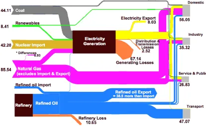
Figure 1.2: Summary of Energy Flows in Scotland in TWh (2002), figure from
[10]
Primary energy sources like natural gas, crude oil, coal or renewable energy
can be transformed to more convenient forms of energy like electricity. Figure
1.2 is an overview of energy flows in Scotland 2002 [10]. It shows that end
users like households, industry and the public sector use a mix of primary
energy and electricity. The energy consumed in households, for example,
predominantly consists of the primary energy source natural gas and electricity.
Electrical energy is very convenient to use and an essential part of the
computer and information society of today. However, it can only be used by a
consumer connected to the grid or to batteries, which causes some limitations if
electricity is used in the transportation sector. Figure 1.2 indicates that electrical
energy is produced out of primary energy with a very poor efficiency, actually
only one third of the primary energy invested into electricity production ends up
[image:13.595.89.504.73.327.2]Figure 1.2 also shows that at present fossil fuels and nuclear energy are used
to generate electricity. The part of electricity produced by renewable energy
sources is small, but steadily increased over the last few years, and is expected
to increase even more in the future [11]. Transforming mechanical and chemical
energy into electrical energy as well as transforming excess electrical energy
into the chemical energy of fuels, both as efficiently as possible, will be one of
the key tasks of a sustainable energy policy. The chemical fuels, produced by
excess electricity in times when the supply of sun or wind energy exceeds the
electricity demand, can be stored and used for transport or to level out the
intermittencies of the renewable energy production.
A possible future vision for a sustainable energy policy could be based on many
decentralised energy centres where energy is produced from renewable
sources. All of these energy centres could be connected by an electrical grid
and each of them could be equipped with facilities to transform electrical energy
1.2. Energy storage
Since most of the renewable energy sources produce energy intermittently, it is
important that the electrical energy produced by them can be stored in times of
excess production and released in times of limited production. Electrical energy
cannot simply be stored in the grid, it has to either be transformed to other kinds
of energy or stored as electrical energy for instance in a capacitor or a
supercapacitor [12].
The most commonly used technique is to use the electrical energy to pump
water to an increased height and store the energy in the form of gravitational
energy [13]. To release the stored energy the water flows down and moves a
turbine. Other mechanical ways of storing the electrical energy are to compress
air [14] or to accelerate a flywheel [15].
Chemical ways of storing electrical energy include the reversible transformation
of chemicals in batteries [16] or redox flow batteries [17] and the use of
electricity for the production of fuels. The most basic fuel is hydrogen, which can
be produced by simply splitting water using electrical energy in an electrolyser.
The main problem of hydrogen as a fuel is its very low volumetric energy
density. To overcome this problem hydrogen can be compressed or even
liquefied using pressure and very low temperature. However, both of these
methods demand additional energy lowering the efficiency of the use of
hydrogen as energy carrier [18]. Hydrogen also can be subject to chemical or
electrochemical reactions, it bonds to other elements creating fuels like
hydrocarbons[19] or ammonia [20], which have higher volumetric densities due
to the fact that they are liquids or at least can be liquefied much easier than
1.3. The role of electrolysers and fuel cells
The main part of electrical energy produced today is produced by burning fuels
in heat engines. The heat of the burning fuel is used to create steam from
water, which runs a turbine connected with an electrical generator.
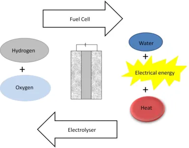
The transformation of the chemical energy of the fuel to electrical energy can
also be done in a different, more direct way, in a device called fuel cell. In a fuel
cell the fuel is oxidised in an electrochemical reaction while at a different place
oxygen is reduced to oxide ions. The flow of electrons from the place of the
oxidation of the fuel to the place where oxygen is reduced directly generates the
electrical energy next to residual heat. Water is created as a by-product. The
main reason for the use of a fuel cell instead of a heat engine to produce
electricity out of a fuel, is the higher efficiency of the transformation process
[21], the same amount of fuel can create more electrical energy when it is
converted in a fuel cell.
A very similar device can be used in the opposite direction. Electrical energy is
used to force electrons to move in the opposite direction, reducing the protons
of water to hydrogen or other fuels and oxidising the oxide ions to oxygen. This
device is called an electrolyser. A reversible fuel cell is a device that can work
1.4. Types of fuel cells
Generally every fuel cell consists of four parts. The two electrodes anode and
cathode are separated by the electrolyte, and the interconnect connects the
single cells with each other and with an outer circuit. At the anode the
continuously fed fuel is oxidised and free electrons are generated. These
electrons move through the interconnect and the outer circuit to the cathode,
where oxygen is reduced to oxide ions. The electrolyte either conducts anions
[image:18.595.98.494.319.655.2]from the cathode to the anode or cations from the anode to the cathode.
Fuel cells differ in the fuels used, the material of the electrolyte, the type of the
charge carrying ions and the operating temperature. Most commonly fuel cells
are classified by the material of their electrolytes.
Solid Oxide Fuel Cells (SOFCs) are defined by their ceramic electrolytes
conducting O2- ions from the cathode to the anode, or in the case of proton
conductive SOFCs, conducting H+ ions from the anode to the cathode of the
fuel cell. Their operation temperature is the highest of all types of fuel cells. This
high operation temperature is responsible for the advantages as well as for the
disadvantages of SOFCs compared to other types of fuel cells. At temperatures
of 700 °C and above a lot of hydrocarbon fuels can be used without an external
reformer and complicated fuel processing. The efficiency is high and can even
be increased by using the hot exhaust gases of the fuel cell for heating or
cooling purposes, or even to run a gas turbine. Combined heat and power
(CHP) systems of that kind can provide efficiencies of over 60%, far more than
conventional electricity generation systems [24]. The negative aspects of the
high operating temperature are long start up and cool down times and problems
with the chemical and mechanical stability of the materials used in SOFCs. High
temperature fuel cells are more suitable for continuous energy production than
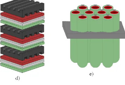
1.5. Fuel Cell Design
Due to the fact that all the components in a SOFC are solid, principally there are
no restrictions about the geometrical design of its general components
electrodes, electrolyte and interconnect. However, most SOFCs are either
configured as flat planes (planar SOFC) or rolled tubes (tubular SOFC). As an
alternative design also a double spiral configuration was patented in
St. Andrews (SOFC roll).
Figure 1.6: different designs of SOFCs: a) planar, b) tubular, c) SOFC roll. The red layers represent the cathodes, the green layers the anodes, the light grey layers the electrolytes and the dark grey parts the interconnect.
For most practical applications the voltage and power of one single fuel cell is
not sufficient, so many of them have to be combined. The possibility to combine
any number of single cells in a modular way, allowing to tailor the fuel cell
1.6. Efficiency of fuel cells
The chemical energy stored in fuel and oxygen can be quantified by the enthalpy difference of the products and the reactants of the cell reaction ΔH. After transforming the chemical energy in a fuel cell only a part of ΔH is
available as electrical energy. The ratio of the amount of useful energy put out
by the fuel cell to the amount of chemical energy put in via the fuel is called
efficiency. The overall efficiency of the fuel cell can be split into a product of
different efficiencies related to the different losses of available energy during the
conversion process.
V J T
F.C.
ε
ε
ε
ε
=
ε
F.C. ... total efficiency of the fuel cellε
T ... thermodynamic efficiencyε
J ... current efficiencyε
V ... voltage efficiencyEquation 1.1.: total efficiency of a fuel cell as the product of different efficiencies
1.6.1. Thermodynamic efficiency
All of the losses of available energy in the conversion process are related to
thermodynamics. Some are impossible to avoid even under ideal conditions,
which, for a fuel cell would mean operation at OCV, with no electrical current
would be reversible and at equilibrium, but not supplying any usable power to
the environment. Thermodynamic efficiency is often used to compare fuel cells
to heating engines, pointing out that, at least at low temperatures, fuel cells are
more efficient than heat engines.
The production of electricity in heat engines is limited by the thermal loss of the
heat of the exhaust gases. Therefore the efficiency of a heat engine, even
under ideal conditions, can never exceed the Carnot efficiency.
H C T
T
T
1
ε
ε
T ... thermodynamic efficiencyTC ... absolute temperature at the engine exhaust [ K ]
TH ... absolute temperature at the engine inlet [ K ]
Equation 1.2: Carnot efficiency of heat engines
The efficiency of electrical energy production by fuel cells will also suffer from
losses related to thermodynamics. Even under ideal circumstances the
efficiency of a fuel cell can never be higher than the ratio of the change of free
H
Δ
S
Δ
T
1
H
Δ
G
Δ
Tε
ε
T ... thermodynamic efficiency of a fuel cellΔG ... free energy of the cell reaction [ J.
mol-1 ] ΔH ... enthalpy of the cell reaction [ J.
mol-1 ]
ΔS ... entropy of the cell reaction [ J.
mol-1.K-1 ]
T ... absolute temperature [ K ]
Equation 1.3: Maximum theoretical efficiency of fuel cells
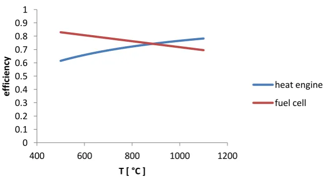
A comparison of the maximal theoretical efficiency of heat engines and fuel
cells at different temperatures shows that the maximal efficiency of heat
engines increases with increasing temperature, the maximum efficiency of fuel
cells decreases with increasing temperature. Figure 1.4. shows the graphs of
[image:25.595.98.429.496.687.2]the theoretical efficiencies of a fuel cell and a heat engine versus temperature.
Figure 1.8: Temperature dependent thermodynamic efficiency of a fuel cell and
0 0.1 0.2 0.3 0.4 0.5 0.6 0.7 0.8 0.9 1
400 600 800 1000 1200
e ff ici e n cy
T [ °C ]
1.6.2. Current efficiency
The current efficiency can be expressed as the fuel utilization energy. It is the
ratio of the amount of current which would be produced if all the fuel supplied
would be oxidized to the amount of current which is actually produced.
F J
i
i
ε
ε
J ... current efficiencyi ... current produced [ A ]
iF ... current produced at 100% fuel utilisation according to Faraday’s law [ A ]
Equation 1.4: current efficiency
The current which should be produced at a certain molar flow rate of fuel can be calculated by Faraday’s law.
dt
dn
F
z
i
FiF ... theoretically produced current [ A ]
z ... amount of electrons produced from one equivalent cell reaction
F ... Faraday constant ~ 96485 [ C.mol-1 ]
dn/dt ... molar flow of fuel [ mol.s-1 ]
1.6.3. Voltage efficiency
The thermodynamic efficiency described in chapter 1.6.2 deals with inevitable
losses occurring even if the fuel cell does not produce power. As soon as
current is drawn from the fuel cell additional losses have to be considered. The
reversible cell potential is reduced because internal resistances of the fuel cell,
working against the movement of the electrons, have to be overcome.
k vk k 0
rev
*
ln
P
F
*
z
T
*
R
E
E
Erev. ... reversible cell potential [ V ]
ΔG ... standard free energy change of the cell reaction at T [ Jmol-1
]
z ... electrons produced from one equivalent cell reaction
F ... Faraday constant ( ~ 96485 ) [ Cmol-1 ]
R ... universal gas constant ( ~ 8.31 ) [ JK-1mol-1 ]
T ... absolute temperature [ K ]
Π
Pkvk ... reaction quotientEquation 1.6: reversible cell potential
The voltage drop whenever electrical energy is drawn from the fuel cell is due to
a combination of activation polarisation, ohmic polarisation and mass transport
polarisation. The contribution of each of these polarisations to the total cell
voltage loss depends on the amount of current drawn from the fuel cell.
Polarisation curves ( IV curves ) are useful performance indicators for fuel cells
and show in their different parts the effects of activation polarisation, ohmic
polarisation and concentration polarisation. These polarisations are described in
Figure 1.9: An idealised polarisation curve shows in its different parts the domination of different polarisations
Unlike the thermodynamic efficiency, the voltage efficiency can be influenced by
the choice of materials for the different parts of the fuel cell. Materials providing
better ionic and electronic conductivity can reduce the ohmic polarisation of the
fuel cell, the choice of suitable catalysts can reduce the activation polarisation
and the porosity and microstructure of the electrodes can influence the
[image:28.595.86.514.97.461.2]The current efficiency and the voltage efficiency are clearly not independent
from each other, but connected by fuel utilisation. A high fuel utilisation means
that the current efficiency is high, but might lead to a low voltage efficiency
because of diffusion limitations. To judge the performance of a fuel cell under
certain conditions it will always be favourable to have a look at the overall
1.7. SOFC materials
The choice of materials for the fuel cell components is particularly challenging
for SOFCs, because of the high operating temperatures. At temperatures of
700 °C to 1000 °C in highly reducing and oxidising environments the danger of
corrosion and unwanted reactions between the different materials of the fuel cell
is potentially very high. The thermal expansion coefficients of the different
materials also have to be reasonably similar to avoid mechanical stress and
fractures during heat up and cool down phases.
1.7.1. Interconnect materials
The interconnect in fuel cells provides the contact between the single cells and
also typically distributes fuel and oxidant to the anode and the cathode side of
the fuel cells. It has to be chemically and mechanically stable in both reducing
and oxidising atmosphere and provide excellent electron conductivity in each of
them.
Stainless steel, the first choice for other types of fuel cells, is problematic in
SOFCs because of the high temperatures causing corrosion and unwanted
reactions with other fuel cell parts. The ceramic material lanthanum chromite (
LaCrO3 ) has been widely discussed, usually doped with divalent ions like
strontium, calcium or magnesium [25], providing p-type conductivity and
chemical and mechanical stability at temperatures up to 1000 °C. High
manufacturing costs and, compared to metal based interconnects, low
electronic and thermal conductivities, however, are disadvantages of this
The development of SOFCs working at temperatures of 850 °C and lower
allows the use of more cost effective metallic materials. Chromium iron alloys of
different compositions are used as interconnect materials and as protective
coatings for stainless steel [26], but on the downside, volatile chromium species
are formed within these materials under the cathode working conditions
poisoning the cathode material [27]. One approach to solve this problem is the
development of new interconnect alloys with a lower level of chromium, which
grow a chromium free e.g. (Fe,Co,Ni)3O4 spinel outer layer exhibiting sufficient
electronic conductivity while avoiding the chromium migration observed from
Cr2O3 layers [28].
1.7.2. Electrolyte materials
At working temperature the electrolyte of a SOFC should show high conductivity
for oxide ions and negligible electron conductivity. It should be dense enough to
prevent gaseous diffusion and provide some mechanical stability. Chemical
compatibility and a similar thermal expansion coefficient to the other materials
are necessary. Materials which are cheap and easy to fabricate and to process
into thin dense films are desirable.
State of the art electrolyte material for SOFCs is yttria stabilised zirconia (YSZ).
Pure zirconia ZrO2 shows very low ionic conductivity and a phase transition
from monoclinic to tetragonal at around 1000 °C, which is accompanied by a
large change in volume, making it difficult to obtain stable sintered products.
The addition of yttria ( Y2O3 ) to zirconia replaces some of the Zr4+ ions with Y3+
ions in the cation lattice and produces oxygen vacancies in the anion lattice due
to charge compensation. At around 8 mol% yttria substitution YSZ shows a
temperature and over 2000 °C. Also around this doping level the oxide ion
conductivity provided by the oxygen vacancies reaches a maximum.
Ionic conductivity in solids can be explained by the hopping model referring to
the hopping of interstitial ions or defects to adjacent equivalent sites. In a small
external field a temperature dependence ( 1/T ) is introduced into the
pre-exponential factor of the Arrhenius equation [29]. The ionic conductivity of
YSZ can be expressed by the modified Arrhenius equation [30].
T R
E Δ A
e
T
A
σ
σ ... ionic conductivity [ Sm-1 ] A ... pre-exponential factor
T ... absolute temperature [ K ]
R … universal gas constant ( ~ 8.31 ) [ JK-1
mol-1 ]
ΔEA ... molar activation energy for the ioniuc conductivity [ Jmol-1 ]
Equation 1.7: Arrhenius equation for the ionic conductivity
When log (σ*T) is plotted against 1/T a straight line can be expected where the slope can be used for the calculation of ΔEA.
Alternative electrolyte materials to YSZ aim for higher ionic conductivity [31],
suitable for operation in a SOFC at lower temperatures (700 °C and below).
Cerium gadolinium oxide (CGO) [32] offers a substantially higher ionic
conductivity than YSZ, but at higher temperatures and reducing conditions
the material, which is intolerable for an electrolyte material. Lanthanum gallate
doped with strontium and magnesium (LSGM) [33] exhibits an ionic conductivity
nearly as good as CGO without electronic conductivity related problems at
higher temperatures. Single phased LSGM materials of sufficient purity are,
however, difficult to prepare and to retain during fuel cell operation. Because of
the reactivity of LSGM with nickel it is necessary to place a buffer layer between
LSGM electrolytes and conventional SOFC anodes to avoid unwanted
secondary phases [34].
1.7.3. Electrode materials
Generally at the electrodes of fuel cells a gas is in contact with a solid surface,
where it undergoes an electrochemical reaction. At the anode a fuel is oxidised
and at the cathode oxygen is reduced to form oxide ions. The electrodes are
porous and ideally provide a big surface area, where gas ionisation or
deionisation reactions can occur. Good electronic and ionic conductivity is
needed to transport the electrons and ions generated or used by the
electrochemical reactions through the electrode material between the reaction
sites and the electrolyte or interconnect. Catalytic activity for the reaction taking
1.7.3.1. Composite electrodes
Since these multiple requirements for electrode materials of SOFCs are hardly
ever possible to meet by one single material, composite electrodes consisting of
two or more materials are commonly used. One material can provide the ionic
conductivity and mechanical stability and the chemical compatibility to the
electrolyte. This material often is identical with the electrolyte material, YSZ,
LSGM or CGO. Another material can be used to provide the electronic
conductivity and catalytic activity for the oxidation of the fuel or the reduction of
oxygen. Since the reaction zone is limited to the so called triple phase boundary
(TPB), areas where both ions and electrons are in contact with the gaseous
phase, the microstructure of composite electrodes is extremely important for
their performance.
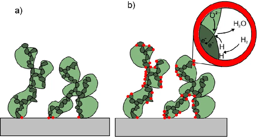
By using materials which are conductive for oxide ions for the scaffold of the
composite electrode, it is possible to extend the reaction zone from the areas
directly connecting to the electrolyte to the whole surface of the electrode. In
figure 1.10 a) the anode does not exhibit any ionic conductivity, and so the
electrochemically active areas are confined to the triple phase boundary
between the pores, the electrolyte and the electrode. The electrochemically
active area in figure 1.10 b) is increased beyond this area because one phase
Figure 1.10: Schematic drawing of the microstructure of a SOFC composite electrode, the anode in this case. The electrolyte is coloured grey, the dark green phase is the anode compound responsible for the catalytic activity and electronic conductivity, the light green scaffold phase is responsible for stability in a) and for stability and ionic conductivity in b). The red dots mark the areas active for the electrochemical reaction
1.7.3.2. Microstructure of composite electrodes
Ideally the number of the electrochemical reaction zones and their overall area
should be as big as possible, which is a matter of the microstructure of the
electrode as well as of its chemical composition, making the microstructure of
composite electrodes a key factor to achieve high performance.
[image:35.595.88.500.75.296.2]Each of the different components of the composite electrode should consist of
well connected grains providing pathways for the transport of electrons and
oxide ions, and the whole electrode phase should be in good contact to the
electrolyte without any delamination. The degree of porosity normally is a
compromise between ensuring sufficient conductivity and mechanical stability
and the access of the gases to all areas of the electrode. Microstructural
stability during long term operation and interruptions of the operation by shut
down and start up phases is desirable.
The microstructure of composite electrodes is intimately linked with the method
of fabrication. Generally the co-firing of the anode and the electrolyte have to be
carried out at high temperatures to fully densify the electrolyte. On the
downside, high firing temperatures lead to coarsening of the microstructure of
the electrode and to a reduction of the electrochemically active area. One way
to avoid these problems connected with a high firing temperature, is the so
called impregnation method [35]. .
1.7.3.3. Cathode materials
At the SOFC cathode oxygen is reduced to oxide ions using electrons provided
through the interconnect. These ions subsequently enter the electrolyte. The
place where these reactions occur must contain gaseous oxygen, electrons and
a possible pathway for the oxide ions to move away. Cathode materials must be
electronically conductive, highly porous to allow contact with oxygen, and
should provide some catalytic activity for the reduction of oxygen. They should
be chemically and mechanically stable at operation temperature and compatible
State of the art SOFC cathodes are composites of the electrolyte material,
mainly YSZ, and ceramic materials with perovskite structures like lanthanum
strontium manganite (LSM), lanthanum strontium ferrite (LSF) or lanthanum
strontium cobalt ferrite (LSCF). LSM is a good electronic conductor and
reasonably compatible with YSZ, but unfortunately it is a poor ionic conductor.
LSM/YSZ composite cathodes show good electrochemical performance at high
temperatures over 800 °C [36]. At lower temperatures mixed ionic and
electronic conductors (MIECs) like LSCF show better performances than LSM
[37].
1.7.3.4. Anode materials
At the SOFC anode hydrogen or other fuels are oxidised and react with the
oxide ions from the electrolyte to form water and other reaction products. The
electrons generated in this oxidation process are removed via the interconnect.
These reactions depend on the presence of gaseous fuels and possible
pathways for the electrons and reaction products to move away. Anode
materials must be electronically conductive, highly porous to allow contact with
the fuel, and should provide some catalytic activity for the fuel oxidation. They
should be chemically and mechanically stable at operation temperature at
1.7.3.4.1. State of the art SOFC anodes
The state of the art anode for SOFCs is a composite of a ceramic and a metallic
material, a so called cermet. The ceramic material is usually identical with the
material of the electrolyte, YSZ, and improves the mechanical stability and
conductivity for oxide ions as well as providing a better match of the thermal
expansion between the electrolyte and the electrode. Metallic nickel particles
alongside the YSZ provide electronically conductive pathways and catalytic
activity for the fuel oxidation. Ni/YSZ anodes exhibit excellent electronic
conductivity and catalytic performance for the oxidation of hydrogen and for
reforming reactions of hydrocarbons.
However, next to these advantages, the system Ni/YSZ exhibits also some
disadvantages when used as a SOFC anode. Firstly, metallic nickel is
catalytically very active for the cracking of hydrocarbons, leading to a build up of
carbon fibres if the fuel cell is fuelled by hydrocarbons. Carbon fibres can lead
to a loss of nickel due to metal dusting, they can produce mechanical stress and
fracture the electrode, or block some of the pores, all of which deteriorate the
performance of the anode. Cracking can be avoided by adding steam to the
fuel, but this also means fuel dilution and a lower overall performance [38] , or
by replacing nickel with copper, which results in problems with the thermal
stability of the anode [39].
At high temperature metallic nickel tends to agglomerate resulting in grain
growth and reduction of the specific nickel surface [40]. Although the anode is
exposed to a reducing atmosphere under working conditions, during start up
and shut down periods it is also likely to be in contact with ambient atmosphere
containing oxygen. Because of this some tolerance to redox cycling is desirable
for SOFC anodes. The oxidation of nickel to nickel oxide causes a massive
volume expansion, leading to volume instability upon redox cycling and a
Lastly, nickel is intolerant to impurities in the fuel, especially sulphur, which
poisons the catalyst and increases the polarisation of the fuel cell. The
poisoning is recoverable at H2S concentrations of 1-5 ppm, but irreversible at
H2S concentrations of 100 ppm and more [41]. Since fuels from organic sources
always contain sulphur it is necessary to clean fuels in a desulphuriser before
the use in SOFCs with Ni/YSZ anodes, adding to the costs of the process.
1.7.3.4.2. Alternative SOFC anodes
There has been a lot of research with the goal of finding alternative anode
materials to overcome the disadvantages and retain the advantages of the
Ni/YSZ anode.
In the first category of alternative anodes, the Ni/YSZ system was retained, but
other components added. To suppress carbon deposition, earth alkaline oxides
like CaO and SrO were added around a quantity of 2 wt% [42]. Preparing
cermets with other metals (cobalt, iron and copper) additional to nickel by
combustion synthesis [43] served the same purpose.
Changing the ceramic part from YSZ to CGO the nickel catalyst inside the
cermet still showed good catalytic activity for the oxidation of hydrogen and
methane [44], [45] and good electrochemical performance [46]. Partly or fully
replacing nickel with copper within this system prevents the formation of carbon
[39], [47], [48]. Adding a mixed ionic and electronic conductor as a third
1.7.3.4.3. Fully ceramic SOFC anodes
A different strategy for alternative anodes for SOFCs is to substitute nickel with
a ceramic phase, eliminating all the problems a metallic phase brings to the
performance of the anode. On the downside it is generally very difficult to find a
ceramic which matches the electronic conductivity and the catalytic activity of
nickel. In the literature predominantly two groups of oxides have been of
interest, chromites and titanates.
Doped Lanthanum Chromites are well known for being good electronic
conductors and chemically and mechanically stable at high temperatures. They
can be used for interconnectors in SOFCs, but their electronic conductivity also
makes them an interesting candidate for a component in a composite anode.
Lanthanum chromite doped with strontium and manganese and cerium (LSCM
and CeLSCM) exhibited good performance as single phase anodes [50] [51],
and even better performance as a composite with YSZ [52] or CGO [53] [54].
The microstructure of the composite anodes turned out particularly important,
especially the microstructural changes upon redox cycling [55] [56].
Lanthanum strontium titanate (LST) was investigated as an anode for SOFCs
[57], but similar to the chromite materials the electrochemical performance was
better when used in composites with YSZ [58]. Of particular interest was the
manganese doped material (LSTM), which next to good electrochemical
performance and compatibility to YSZ [59] [60] showed interesting
microstructural behaviour upon redox cycling. After the impregnation in air
LSTM forms a dense coating on the YSZ scaffold, reminiscent of the wetting
behaviour of liquids on solid surfaces. Under fuel conditions the dense coating
breaks into interconnected nanoparticles, providing an uniform distribution of
1.7.3.4.4. Catalysts for SOFC anodes
Generally catalysts accelerate the rate of a reaction by lowering the reactions
activation energy but do not change the thermodynamic equilibrium. Catalysts
play a key role in the electrochemical performance of fuel cells [61]. The
relevant reactions in a solid oxide fuel cell can be the oxidation of hydrogen,
direct oxidation of methane or the steam reforming of methane or higher
hydrocarbons.
In the state of the art SOFC anode metallic nickel is the catalyst. Nickel is well
known to have high catalytic activity for the oxidation of hydrogen and also for
steam reforming and is industrially utilised for these reactions. As mentioned in
chapter 1.7.4.1 nickel unfortunately also catalyses the cracking of hydrocarbons
and formation of carbon fibres, which are unwanted reactions in the operation of
solid oxide fuel cells and it is sensitive to poisoning by sulphur.
Precious metal catalysts like platinum, palladium and rhodium are well known
oxidation catalysts as well and widely used in research [62]. However, their high
price is a major drawback for commercial use and they suffer from similar
poisoning problems as nickel.
Cerium oxide shows good electrochemical performance and good catalytic
activity [61], especially for the oxidation of methane [63]. Mixed ionic and
electronic conductive doped perovskite oxides can work as oxidation catalysts
as well due to their ability to reversibly accommodate and release lattice oxygen
at high temperatures [64].
Recent research work points out the benefits of so called “intelligent catalysts”,
situ exsolutions of nanoparticles of the catalytically active metal [65] [66]. Thus
the catalyst has a very high specific area and the anode shows better
electrochemical performance.
1.7.3.5. Impregnation method
In the impregnation method for the fabrication of composite materials the
scaffold phase is fired at high temperatures to form a porous skeleton, and
subsequently an aqueous precursor of the second material is infiltrated into the
pores of the skeleton, to form the desired material in situ after firing at lower
temperatures.
This method offers big advantages if the two components of a composite have
to be fired at different temperatures, either because one of the materials is
instable at the temperature necessary for the formation of the other material, or
because one of the materials needs to be distributed in small particles for
optimal performance and shows unwanted coarsening if the temperature is too
high.
The electrodes of solid oxide fuel cells can consist of a skeleton phase to
provide ionic conductivity and contact to the electrolyte, a second phase for
electronic conductivity and sometimes a third phase providing catalytic activity
for the electrochemical reactions, as described in chapter 1.7.3. Using the
impregnation method for the fabrication of composite electrodes allows the
co-firing of the skeleton part of the electrode with the electrolyte at high
temperatures of 1400 °C to 1500 °C provides a good bondage between these
two phases, avoiding delamination and resulting in an ionic conduction path to
all areas of the electrode, increasing the triple phase boundary. The lower firing
between 1000 °C and 1200 °C reduces the risk of unwanted solid state
reactions between the different electrode materials during the fabrication
process [67]. Generally lower firing temperatures at the fabrication also lead to
a smaller grain size of the catalytic active phase, which increases the
catalytically active area.
Cathodes prepared by impregnation of lanthanum strontium manganate (LSM)
into a YSZ skeleton have been used successfully for a long time [68], and for
composite anodes of YSZ and the mixed ionic and electronic conductors
lanthanum strontium cobaltate (LSC) and lanthanum strontium ferrate (LSF),
the impregnation method is even more important, because these perovskites
show unwanted reactions with YSZ at temperatures larger than 1000 °C [69].
In anodes for SOFCs the impregnation method has been used to improve the
performance of conventional nickel based anodes by the impregnation of YSZ
and CGO nanoparticles, inhibiting nickel agglomeration and sintering [70]. The
impregnation of precious metals like palladium or platinum improves the
performance of anodes [71] and cathodes [72] by introducing a catalytic effect
for the fuel oxidation, especially if the particles are very small, as provided by
the low temperature firing after impregnation. A cheaper way of introducing a
catalyst next to precious metals is the impregnation of cerium oxide into the
anodes of solid oxide fuel cells [73]. Fully ceramic anodes based on YSZ and
doped lanthanum strontium chromates [55] and lanthanum strontium titanates
[55] [60] were successfully prepared using the impregnation method, and the
importance of the microstructure for the performance of the anode in these
compositions was investigated [55].
Recently a large area solid oxide fuel cell (5*5 cm) was fabricated using the
impregnation method. The large area made it challenging to achieve a gas tight
1.7.4. Perovskite oxides for SOFCs
Perovskite oxides are mixed oxides with the general formula ABO3. The
A-cations are relatively large, similar to the size of the oxide anions, and form a
cubic closed packed structure together with the anions, containing one A-cation
for every three oxide ions. One quarter of the octahedral holes of this cubic
closed packing is filled with the significantly smaller B-cations. The unit cell of
the ideal perovskite can be seen as a cube with the corners occupied by the
B-cations, the centre by an A-cation and the middle of the edges by one oxide
ion each. Every B-site cation is surrounded by 6 oxide anions forming an
octahedron, while the A-site cations have a 12-fold cuboctahedral coordination.
Figure 1.11: Schematic illustration of a perovskite oxide. The A-site cation is coloured yellow, the B-site cations blue and the oxide ions red. The size of the spheres in the drawing does not reflect the correct ratio of the ionic radii of the ions
For an ideal cubic single cell the sum of the radii of the B-site cation and the oxide ion has to be √2 times the sum of the radii of the A-site cation and the
oxide ion. Most of the real perovskites do not have this ideal cubic structure, in
fact, the perovskite system is known to be very flexible tolerating deviations
from the ideal ratio of radii, leading to a big variety of possibilities for cations to
[image:44.595.136.310.330.499.2]and hence of the distortion of the unit cell can be expressed by the Goldschmidt factor.
)
r
r
(
2
r
r
t
O B O At ... Goldschmidt tolerance factor
rA ... ionic radius of the A-site cation [ m ]
rB ... ionic radius of the B-site cation [ m ]
rO ... ionic radius of the oxide ion [ m ]
Equation 1.8: Goldschmidt tolerance factor
In an ideal perovskite the tolerance factor would be one, however, stable
perovskites are known in a range of tolerance factors from approximately 0.8 to
1.1. The tilting of the BO6 octahedra in case of the tolerance factor being
smaller than one can result in maintaining the cubic unit cell or a change to the
orthorhombic system, depending how big the deviation is. If the tolerance factor
is smaller than 0.8, the ilmenite structure will become more stable than the
perovskite. A tolerance factor bigger than one can lead to hexagonal variants of
the perovskite structure. The layers are stacked in a hexagonal close packed
structure instead of cubic closed packed, and hence the BO6 octahedra are
sharing faces instead of corners.
The sum of the positive charges of the A- and B- cation in an ideal perovskite is
+6, however, in real perovskites the B-cation often is multivalent, which,
depending on the redox conditions in the environment, may lead to a sum
different from +6. Doping of the A- or B-site with ions of a valence different from
the original ions also leads to a deviation from the +6 charge of the cations in
the perovskite, and not all of the A sites of the perovskites have to be filled with
deficiency. Whatever the reason for a cation charge different from +6, to retain
charge neutrality, the amount of oxide ions has to change, leading to oxygen
deficient perovskites in case of a cation charge sum smaller than +6, or oxygen
excess perovskites in the case of a charge sum bigger than +6. Oxygen
deficiencies as well as A-site deficiencies can be distributed randomly over the
whole perovskite crystal, but also can be ordered, leading to superstructures
and to layered perovskites.
Figure 1.12: Examples for perovskite nonstoichiometry.
The accommodation of cations slightly smaller or bigger than the demands of
the ideal structure, the possibility of doping A- and B-site, the tolerance for
vacancies on the A-site and for excess or vacancies of oxygen with ordering
and superstructures all lead to an exceptional variety of chemistry and structure
in the perovskite family. This remarkable versatility of the perovskite oxides
leads to a huge range of magnetic, optic, electrical and catalytic properties
which often can be tailored for certain applications by doping.
Next to this chemical flexibility, perovskites generally show excellent thermal
and mechanical stability even above 1000 °C and during temperature cycling,
perovskite oxides also exhibit good chemical and mechanical compatibility with
electrolyte materials like YSZ and CGO. Transition metal ions like titanium,
niobium or vanadium on the B-site of the perovskite can adopt different
oxidation states, thus generating free electrons and electronic conductivity
under reducing conditions. Multivalent B-sites and doping by cations with a
valence different from the original ions lead to oxygen excess or oxygen
deficiency, both providing the possibility of ionic conductivity for oxide ions.
Through doping it is possible to provide perovskite materials which show mixed
ionic and electronic conductivity either at reducing or oxidising conditions,
making them ideal materials for fuel cell anodes or cathodes, respectively.
In the past perovskite materials have been reported as electrolyte, anode, cathode and interconnect materials for SOFCs, making an “all perovskite”
SOFC fuel cell at least a thinkable option. Perovskite materials of the
composition La0.8Sr0.2Ga0.8Mg0.2-xCoxO3-δ (LSGMC) have been successfully
tested as SOFC electrolytes at temperatures as low as 650 °C, with an oxide
ion conductivity better than YSZ [75]. La0.8Sr0.2MnO3 (LSM), a perovskite oxide
as well, is the state of the art material for SOFC cathodes [76]. At lower
temperatures, perovskites of the composition La0.8Sr0.2FeO3 (LSF) [77],
La0.8Sr0.2CoO3 (LSC) [78], La0.8Sr0.2CoxFe1-xO3 (LSCF) [79] [77] and
NdBa1-xSrxCo2O5+δ (NBSCO) [80] showed even better electrochemical
performance. Doped LaCrO3 is the state of the art interconnect material for fuel
cells operating at temperatures too high to allow steel [81] [25].
As an anode material, La0.75Sr0.25Cr0.5Mn0.5O3 (LSCM) presents good
electrochemical performance together with both YSZ electrolytes [50] [55] and
LSGM electrolytes [82]. A-site deficient titanates like La0.4Sr0.4TiO3 show
excellent electronic conductivity and also some oxide ion conductivity under
reducing conditions [83], making them very interesting materials for SOFC
anodes. By doping the B-site of these titanates with gallium, iron or nickel the
of the performance in composite anodes with YSZ, probably due to improved
wetting of the YSZ scaffold during the production of the composite [55]. Another
promising double perovskite anode material is Sr2MgMoO6-δ, performing
[1] “Statistical Review of World Energy.” BP, 2011.
[2] “Key World Energy Statistics.” International Energy Agency, 2010.
[3] “Energy Use Per Capita.” World Bank, World Development Indicators, 2012.
[4] L. Maugeri, “Oil: Never Cry Wolf--Why the Petroleum Age Is Far from over,” Science, 304, 1114–1115, 2004.
[5] N. A. Owen, O. R. Inderwildi, and D. A. King, “The status of conventional world oil reserves—Hype or cause for concern?,” Energy Policy, 38, 4743–4749, 2010. [6] J. Hansen, M. Sato, and R. Ruedy, “Perception of climate change,” PNAS, 2012.
[7] “Fourth Assessment Report, Summary for Policymakers.” UN Intergovernmental Panel on Climate Change (IPCC), 2007.
[8] I. Dobrev, B. Mandadzhiev, R. Petranov, and B. J. Savilonis, “Implementation of Renewable Energy Sources in the State of California.” Worcester Polytechnic Institute, 2007.
[9] High Level Panel of Experts, “Price volatility and food security.” UN Committee on World Food Security, 2011.
[10] “The Scottish Energy Study Vol 1: Energy in Scotland: Supply & Demand.” The Scottish Government, 2006.
[11] J. Muth and E. Smith, “45% by 2030.” European Renewable Energy Council (EREC), 2011.
[12] P. Simon and Y. Gogotsi, “Materials for electrochemical capacitors,” Nature Materials, 7, 845–854, 2008.
[13] D. Rastler, “Electricity Energy Storage Technology Options.” Electric Power Research Institute (EPRI), 2010.
[14] S. Succar and R. H. Williams, “Compressed Air Energy Storage: Theory, Resources, and Applications for Wind Power.” Princeton Environmental Institute, 2008.
[15] R. Hebner, J. Beno, and A. Walls, “Flywheel batteries come around again,” IEEE Spectrum, 39, 46 –51, 2002.
[16] N.-K. C. Nair and N. Garimella, “Battery energy storage systems: Assessment for small-scale renewable energy integration,” Energy and Buildings, 42, 2124–2130, 2010. [17] C. Ponce de León, A. Frías-Ferrer, J. González-García, D. A. Szánto, and F. C. Walsh,
“Redox flow cells for energy conversion,” Journal of Power Sources, 160, 716–732, 2006.
[18] P. P. Edwards, V. L. Kuznetsov, W. I. F. David, and N. P. Brandon, “Hydrogen and fuel cells: Towards a sustainable energy future,” Energy Policy, 36, 4356–4362, 2008. [19] S. H. Jensen, X. Sun, S. D. Ebbesen, R. Knibbe, and M. Mogensen, “Hydrogen and
synthetic fuel production using pressurized solid oxide electrolysis cells,” International Journal of Hydrogen Energy, 35, 9544–9549, 2010.
[20] R. Lan, J. T. S. Irvine, and S. Tao, “Ammonia and related chemicals as potential indirect hydrogen storage materials,” International Journal of Hydrogen Energy, 37, 1482– 1494, 2012.
[21] M. M. Mench, "Fuel Cell Engines", John Wiley & Sons, 2008.
![Figure 1.4: Schematic drawing of an individual fuel cell, image from [22]](https://thumb-us.123doks.com/thumbv2/123dok_us/8927789.391649/18.595.98.494.319.655/figure-schematic-drawing-individual-fuel-cell-image.webp)