Application of Exsolved Structures as a Route to More Robust Anodes for Improved Biogas Utilisation in SOFCs
M. Cassidy, S. Gamble, and J.T.S Irvine
School of Chemistry, University of St. Andrews, St. Andrews, KY16 9ST, UK
Biogas is a potentially readily available fuel which could be especially useful when combined with the efficient energy conversion in SOFCs. This could be especially important in rural or remote locations where grid electricity is not available. Biogas
contains mixture of methane CO2 with inherently high levels of
H2S, therefore to improve performance in biogas more robust
anodes are required that are more tolerant to both carbon and sulphur. In this paper the use of catalyst nanoparticles exsolved onto porous as a possible method of producing more resistant structures is discussed. All of the options showed good performance in reformed biogas mixtures with the exsolved structures showing improved resistance to carbon deposition. The performance of all dropped when exposed to sulphur, however many were also observed to recover once this was removed and so give encouragement for the development of robust anodes that can withstand sulphur breakthrough without catastrophic stack failure.
Introduction
Biogas is a potentially widely available fuel derived from the anaerobic digestion of biological materials such as animal waste. The nature of this fuel source predicates its availability to areas of a more rural nature and as such can be a valuable resource in more remote areas where supply of other energy vectors (such as an electricity grid) can create significant logistical issues. Where Biogas is currently utilized it is often burnt in a reciprocation engine to drive a generator for the supply of electricity. This is a low efficiency method of energy conversion and much of the energy is lost in the process. A better method would be direct electrochemical conversion, taking the higher conversion efficiencies offered by solid oxide fuel cells to improve the utilisation of biogas and provide an efficient source of electricity for remote or off grid locations.
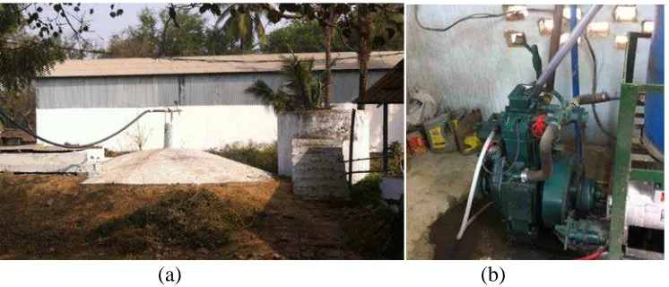
Figure 1 shows a typical installation in rural India. Here manure is collected from approximately 70-80 cattle and dried before being fed in to the digester shown in Fig 1a. The biogas is taken from the top of the digester and fed through scrubbers to remove
excess water, CO2 and H2S before being fed into a reciprocating engine to generate
(a) (b)
Figure 1. Anaerobic digester producing biogas on a rural cattle farm in India showing (a) the digester vessel and (b) the reciprocating engine for electricity generation.
The use of biogas as a fuel has already been demonstrated in fuel cell systems. The higher temperature fuel cell variants such as molten carbonate fuel cells (MCFC) and solid oxide fuel cells (SOFC) are generally more suited to running with biogas, this is due to their greater tolerance to fuel impurities and the potential for internal reforming (1). Of the high temperatures cell types SOFC are potentially more suited to biogas operation due to high power densities, leading to smaller, more compact devices and the completely solid nature of the stack lending itself to system scalability. This makes it highly relevant to smaller scale distributed power scenarios such as remote or rural off grid applications.
Biogas is the product of the anaerobic digestion of natural waste materials such as animal manures and slurries. The product gas is composed mainly of methane and carbon dioxide, however the ratio of the two is not fixed due to natural variations in the digestion
process. While the presence of CO2 is advantageous to help the reformation of methane,
the generally accepted average mix of a biogas is 60% methane and 40% CO2 which does
not provide enough of the latter gas to prevent carbon deposition on its own (2). Therefore additional reforming strategies are required.
Biogas also contains significant amounts (~ 500ppm) of sulphur dioxide (H2S) which
is a well known poison to SOFC Ni based anodes. Even when present in very small quantities, 1-10ppm, it can be seriously detrimental to performance (3), effects which were confirmed in studies investigating direct utilization of biogas in SOFCs (4).
Therefore systems must be in place to remove H2S from the fuel stream and while a
number of proven options exist for this they do add cost and complexity to system operation and maintenance and can still fail leading to sulphur breakthrough.
decomposed to form the particle of by an exsolution process where the catalyst particle precipitates from the parent perovskite lattice under reducing conditions. (5,6). In this paper, some of the recent activities at St Andrews to improve anode robustness in biogas through catalyst exsloution are discussed.
Experimental
Standard Biogas Mixture
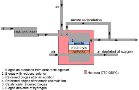
Anodes were tested on a standard reforming biogas mixture developed as part of the project and described in detail elsewhere (7). Figure 2 shows a hypothetical system and detailing the significant fuel processing points. The mixture represented by the standard
reforming mixture is the product of a 63:37 methane:CO2 input biogas exposed to 25%
recirculation of an 80% utilised fuel to result in a gas mixture of 36% CH4, 26% CO2,
20% H2O, 4% H2 and 4% CO. For impurity testing H2S was added to this mixture at
5ppm. Catalyst function was assessed as a function of reforming activity. As well as the standard reforming mixture some specimens were tested in a 50:50 mixture of methane to
CO2 to investigate performance in dry reforming conditions this represents a
[image:3.612.90.560.361.666.2]desulphurised mixture before any further additions of air, steam or recirculated anode gas, close to point 2 in Figure 2.
Exsolved Structures and Reformation Testing
Exsolved materials were based on a 20% A-site deficient perovskites of Ca doped lanthanum titanates. The A-site deficiency promotes the exsolution of B-site cations as metal nanoparticles when exposed to a reducing atmosphere. These were doped with various catalyst materials in this study Ni and Rh are the catalysts of interest. Materials were synthesised using a solid state method where stoichiometric amounts of starting materials (oxides or carbonates) along with dopant materials, either Rh(NO3)3, Ni(NO3)2
or a mixture of these, were mixed in acetone with a dispersant using ultrasonic agitation. This mixture was then dried and calcined at 1000°C for 12 hours before further milling in a planetary ball mill. After drying the powder was pressed into pellets before firing at 1400°C for a further 12 hours. The phase purity of the final powders was checked using X-ray diffraction.
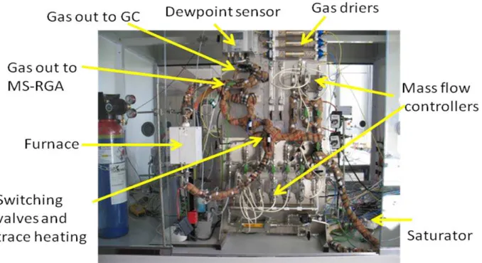
Tests were carried out in a multi-gas flow rig, shown in Figure 3. This could mix up to 10 gases including inert carrier gases, reducing mixtures, the standard reforming biogas
mixture, the dry reforming mixture and addition of H2S contaminant gas, normally at
5ppm. Gas humidification was achieved using a temperature controlled saturator with dew point sensor. All gas lines were trace heated to prevent condensation and gas could be routed through the test furnace or bypassed. Catalytic and reforming tests were carried out in a quartz tube reactor located in the furnace. Gas analysis was carried out by GC-MS. Typical test temperatures were 900°C with specimens being pre-reduced in a
5%H2/Argon mix at 900°C for 30 hours before testing to allow for exsolution of the
[image:4.612.134.473.390.575.2]catalyst.
Figure 3. Multigas test rig for reforming and cell testing.
Results and Discussion
Exsolved Materials Synthesis and Microstructure
(LaCaCe)(NiTi)O3
(LaCaCe)(Ni RhTi)O3
[image:5.612.176.444.63.261.2](LaCaCe)(RhTi)O3
Figure 4. XRD Patterns for doped A-site deficient perovskites in the as synthesised form. The patterns are shown in the same order (bottom to top) as presented in the legend.
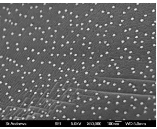
The evolution of the catalyst nanoparticles on the surface of the scaffold can be seen in Figure 5, with exsolution observed on the surface of the perovskite scaffold. Some differences in the number, spacing and preferred surface of exsolution were observed depending on the precise composition and further study of this is ongoing to assess how that can be used for further optimisation.
Figure 5. Microstructure of the exsolved Ni nanoparticles on the surface of the perovskite scaffold.
The reforming activity of the pure Ni dopant is shown in Figure 6. The conversion of methane and CO2 is evident with H2 and CO levels significantly higher than the 4% of
each in the original mix so demonstrating good reforming capabilities in this material. On introduction of the H2S the reforming rapidly degrades, this is most likely due to sulphur
species blocking the active Ni site and is likely similar in nature to that seen in conventional Ni cermets and suggesting that the size of the Ni catalyst does not have a great influence on the poisoning mechanism and that nanophase materials in themselves offer no great advantage in the poisoning effects of sulphur. It is encouraging to note that
on removal of the H2S the reforming activity rapidly recovers and that in just over 60
minutes after the H2S has been removed from the gas stream the reforming curve is
[image:5.612.228.385.392.521.2]Figure 6. Reforming activity of Ni Doped perovskite in standard reformed biogas mixture at 900°C before, during and after exposure to sulphur.
The Rh containing catalysts were tested in a gas composition representing a dry biogas
mixture of 50:50 ratio of methane and CO2 with no added humidification. Results are
presented in figure 7. Good initial conversion rates are evident in both the Ni/Rh mix and the pure Rh with the former having slightly better conversion and the latter also showing some slight degradation in initial conversion rates. This could be linked with observed morphological differences between the Ni containing catalysts and the pure Rh however more work is required to better understand these relationships.
(a) (b)
Figure 7. Dry reforming behaviour of (a) Ni/Rh dopant and (b) pure Rh dopant in a 50:50 mixture of CH4 and CO2 both before during and after H2S exposure.
On introduction of the H2S both catalysts show rapid degradation in gas conversion.
However it is of interest to note that the pure Rh still retains some conversion activity producing a little H2 and CO even during sulphur exposure. Also the Ni/Rh mixture still
the poison. Although recovery does not seen to be quite as complete in the pure Rh catalyst it could be argued that the point to which it has recovered is in line with the slight underlying degradation in performance that was observed in the initial stages of the test.
The recovery observed in all specimens on removal of the sulphur is particularly encouraging. The creation of an anode fully tolerant and able to run directly in sulphur containing fuels is always going to be a difficult proposition. The first stage to improving cell robustness to sulphur poisoning is to provide systems in which this exposure to some sulphur is not catastrophic to the cell. It is likely that an SOFC system will always have some form of sulphur removal installed. This will likely be more to satisfy emissions legislation rather than for protection of the stack. Indeed this is also the case in systems using reciprocating engines such as that shown in Figure 1 where gas purification systems are present to maximise the efficiency of combustion. However such systems do occasionally fail and can allow sulphur compounds to break through to the cells. In this case a cell material that shows minimal damage and is able to recover after such exposure would be advantageous in the realisation of robust cells for use in aggressive fuel environments such as biogas.
Further observations have suggested that the nature of the exsolved particle may have additional benefits in resistance to carbon deposition. When tested on the standard reforming biogas mixture at 900°C nickel catalyst infiltrated on LST scaffolds showed similar initial catalytic performance to exsolved Ni structures. However the infiltrated structures later revealed carbon deposition when temperature programmed reduction was carried out after the test. No such carbon evolution was observed with the exsolved Ni. The Ni nanoparticles arising from the exsolved structure can be seen in Figure 5 and it is known from previous similar work that such Ni infiltration will result in nanoparticles of Ni (8). This similarity in microstructure is reflected in the initial performance observed. However it is thought that the process of the exsolution may result in local changes to the underlying lattice around the exsolved particle which helps protect against carbon deposition and work is on-going to better understand and fine tune these aspects of the surface chemistry
Conclusions
A-site deficient perovskites doped with Ni and Rh were synthesised and shown to exsolve nanoparticles on reduction. Initial performance in standard biogas mixtures was similar to infiltrated structures. Catalytic performance in the exsolved structures was better when Ni was present, this was possibly helped by morphological differences in the catalyst observed in these materials. All suffered performance degradation in the presence
of H2S but were observed to recover to close to initial performance on removal of the
poison. Improved tolerance to carbon formation was observed and may be due to local lattice variation around the pinned nanoparticles.
Acknowledgments
The authors would like thank Dr Dragos Neagu for his help and advice on the design of the perovskite compositions and Dr Jianjun Ma for help with testing and project discussions. We would also like to thank the EPSRC-DST India-UK Collaborative Research Initiative in Fuel Cells project EPI037016/1 “Advancing Biogas through Fuel Flexible SOFC” for funding this work.
References
1. B.C.H. Steele, Nature, 400 (1999), 619-621.
2. J. Van Herle, Y. Membrez, O. Bucheli, J. Power Sources, 127, (2004), 300-312.
3. Paloma Ferreira, CIEMAT-CSIC, Utilisation of Biogas in Fuel Cells, September
17th 2004, Hamburg, Germany.
4. Yusuke Shiratori, Takeo Ijichi, Toshihiro Oshima, Kazunari Sasaki, in Proc Eur.
SOFC Forum 2010.
5. G. Kim, G. Corre, J.T.S. Irvine, J.M. Vohs, R.J. Gorte, Electrochem. & Solid
State Lett., 11 (2008) B16.
6. D. Neagu, G. Tsekouras, D. N. Miller, H. Menard and J. T. S. Irvine, Nat. Chem.
5 (2013) 916-923.
7. S.R. Gamble, D. Neagu, J.T.S. Irvine, ECS Transactions, 57(1) 1527-1532 (2013)
8. S. Boulfrad, M. Cassidy, E. Djurado, J.T.S Irvine, G. Jabbour, Int. J. Hydrogen