Burroughs
B 5500
ELECTRONIC INFORMATION
PROCESSING SYSTEM
DISK SYSTEM OPERATION MANUAL
Equipment and Systems Marketing Division
Sales Technical Services
Systems Documentation
Burroughs Corporation
~
Copyright ~ 1966 Burroughs Corporation
SECTION
2
TABLE OF CONTENTS
TITLE
I NTRODUCTI ON • •
SYSTEM DESCRIPTION •
General • • • • •
Functional Description
System Design • • •
Data Communications Systems
SYSTEM EQUIPMENT ~ .
General • • •
Operator Console
Control Panel
Message Printer
Functional Characteristics
Contro 1 Pane 1 •
B 122 Card Reader •
Functional Characteristics ••
Control Panel
Operating Procedures
Not Ready Conditions
Card Jam
Stacker Fu 11
Cover Not In Place Empty Hopper
Stop Switch Pressed.
Feed Check Indicator Lit
Read Check Indicator Lit
PAGE
• xx
1-1
1-1
1-2
1-2
1-3
• 2- 1
• 2- 1
• 2- 1
. • • 2-2
2-5
· 2-6
• 2-7
· 2-8
· 2-9
• 2-10
· 2-13
• 2-14
• 2-15
• 2-17
• • 2 - 1 7
• 2-17
· 2-17
• 2-18
SECTION
TABLE OF CONTENTS (cont)
TITLE
Validity Check Indicator Lit
Operator Maintenance • • • • •
B 123/B 124/B 129 Card Readers
B
124 Card ReaderFunctional Characteristics
Control Panel
Operating Procedures.
Not Ready Conditions ••
Read Check Condition
Card Jam
Stacker.Full
. . .
·
Cover Not In Place
Empty Hopper
.
.
. ·
Stop Switch Pressed
·
Read Check Indicator
.
Lit
Feed Check Indicator Lit
.
. .
Validity Ch~ck Indicator Lit
Operator Maintenance ••
B 303 Card Punch
Functional Characteristics.
Control Panel
Operating Procedures
Unloading Cards
Not Ready Conditions.
. .
.
. .
PAGE
• • 2-18
2-18
2-20
• • 2-20
• • • • 2 -2 1
2-22
· 2-24
2-31
• 2-31
· • • • 2-32
• • 2-34
· • . . 2-35
2-35
· . 2 - 35
2-35
2-35
• • 2-37
• • 2-
3 7
• . 2-38
2-39
· • • • 2-40
• • 2-43
2-44
SECTION
TABLE OF CONTENTS (cont)
TITLE
Stop Switch Pressed.
Empty Hopper
Cover Opened
Card Not At Ready Station
Punch Die Not In Place
Card Not At Ready Station.
Punch Check Indicator Lit
Stacker Full
Operator Maintenance.
B 304 Card Punch
Functional Characteristics.
Control Panel
Operating Procedures.
Unloading Cards
Not Ready Conditions.
Feed Check Indicator Lit
Stop Switch Pressed
Empty Hopper
Feed Roll Block Not Locked
Punch Block Not Locked
Card Not At Pre-Punch Station.
PAGE
· 2-50
· 2-50
2-51
· 2-51
· 2-51
· 2-51
· 2-51
· 2-52
· 2-52
• • 2-53
• • 2-54
· . 2- 55
• • 2-
58
· • 2-60
• • 2-61
. . • . . 2-62
· • 2 -65
. . • 2-65
2-65
2-65
· 2-66
Primary, Error, Auxi liary Stacker Full
· 2-67
2-67
Covers Not In Place.
Punch Check Indicator Lit ••
Operator Maintenance ••
SECTION
TABLE OF CONTENTS (cont)
TITLE
B 320/B 321/B 325/B 328/B 329 Line Printers
B 321 Line Printer
Functional Characteristics
Control Panel
Forms Hand1 ing
Tape Punching
Operating Procedures •
Changing The Ribbon
Inserting The Carriage Control Tape
Tape And Forms Registration
Not Ready Conditions • • . • •
End Of Paper Indicator Lit
Print Drum Not In Position
PAGE
• 2-69
• 2-69
2-70
2-71
· 2-73
· • 2-74
2-76
· 2-81
· 2-86
• • 2- 87
2-88
• 2-88
· • 2-88
Line Selection Knob In N Position . • 2-89
Paper Slews For More Than One Second . . . • 2-89
Stop Switch Pressed • .
Operator Maintenance.
B 141 Paper Tape Reader.
Functional Characteristics.
Channel Select Plugboard.
B 142 Input Code Translator
Control Panel
Operating Procedures.
Stopping Tape Movement
• 2-89
· . 2-89
· 2-90
· 2-92
· . 2-92
• • 2 -93
2-97
SECTION
TABLE OF CONTENTS (cont)
TITLE
Applying Adhesive Opaque Strips
Operator Maintenance
8 341 Paper Tape Punch
Functional Characteristics ••
Channel Select Plugboard
Code Translator
Control Panel
Loading Paper Tape •
Unloading Tape ••
Rewinding Tape.
Chad Receptacle
Splicing Paper Tape
Operator Maintenance ••
8 421/8 422/8 423/B 424/8 425 Magnetic Tape Units
8 422 Magnetic Tape Unit
Functional Characteristics.
Control Panel
Loading The Supply Reel
Unloading The Supply Reel
Loading The Take-Up Reel • • .
Unloading The Take-Up Reel.
Rewinding
Attaching Leaders
Splicing Magnetic Tape
Operator Maintenance •
PAGE
• • 2 - 106
· 2-107
• • 2-109
2-110
· • 2 - 111
· .2-112
• . • 2-116
• 2-119
· 2-121
• 2-122
· 2-122
· 2-122
2-124
2-125
2-125
· 2-126
· • 2-128
· 2-130
· • . 2 - 134
· 2-135
· 2-136
· . . 2-137
• •• 2-137
· 2-139
SECTION
TABLE OF CONTENTS (cont)
TITLE
Magnetic Tape Care
Magnetic Tape Storage
Magnetic Tape Handling • .
Magnetic Tape Loading
Magnetic Tape Library Procedures •
Disk File System
Functional Description • .
B
450
Disk File/Data Communication Basic Control • . • • . • • . . .B
451
Disk File Expanded Control B5470
Disk F~le Control Unit • . B471
Disk File Electronics .UnitB
471
Control Panel Disk Lockout SwitchesB
475
Disk File Storage Module Data Communication System.Functional Description •
B
5480
Data Communication Control Unit B481
Teletype Terminal UnitB
483
Typewriter Terminal Unit B493
Typewriter Inquiry StationB
484
TWX Terminal Unit And Station • . TWX Network EquipmentStation Character Set
TABLE OF CONTE NTS (con t)
SECTION TITLE PAGE
Data Transmission System. 2-160
Functional Description 2-161
B 249 Data Transmission Control Unit
.
·
·
·
· ·
·
2-161B 487 Data Transmission Terminal
Unit (DTTU)
.
.
.
.
.
.
.
.
.
. ·
·
·
2-162Buffer Conditions
.
.
.
.
.
·
·
·
·
2-163Line Adaptors
.
. ·
· ·
2-165Typewriter
·
·
· ·
2-166Teletype Networks
.
2-167801 Automatic Calling Uni t (ACU)
·
· ·
·
2-1683 LOADING AND MAINTAINING THE SYSTEM 3-1
General 3-1
Disk File System Programs 3-1
Disk File System Tape.
· · · ·
·
3-1Disk File MCP Loader 3-2
Cold Start Deck • • • 3-3
Disk Ha 1 tiL oad Button • . 3-3
Load Control Cards 3-3
Symbol Tape • . • • 3-4
Symbolic Patch Decks 3-4
Updating System Programs 3-5
Disk File System Loader 3-6
Cold Start Routine 3-6
Direct Card 3-7
[image:11.613.112.557.69.741.2]SECTION
TABLE OF CONTENTS (cont)
TITLE
ESU Card
Date Card • -0
File Card Group 0 0
Opt i on Cards
USE ORA Card -- OPTN
47
Card 0 0 0USE ORB -- OPTN
46
Card 0.
.
0TYPE BOJ Card OPTN
45
CardTYPE EOJ Card OPTN
44
Card 0. .
TYPE OPN Card OPTN
43
CardUSE TERMNATE Card -- OPTN
42
Card . TYPE DATE Card OPTN 41 Card TYPE TIME Card OPTN40
CardUSE ONE BREAK Card OPTN
39
Card USE AUTOPRNT Card OPTN38
Card.
.
.
. .
PAGE3-8
3-8
3-9
3-11
3-11
3-12
3-12
3-13
3-13
3-14
3-15
3-15
3-16
3-17
TYPE TUWAITING Card -- OPTN
36
Card. .3-17
TYPE CMPLRFIL Card -- OPTN
35
Card TYPE CLOSE Card -- OPTN34
Card s • TYPE ERRORMSG Card OPTN33
Card3-18
3-18
3-19
STOP Card
3-20
Dis k L oa d But t on Car d 3 - 2 0
Control Cards Used To Load Compilers To Disk.
3-20
System Start Up Procedure
3-20
Loading The Disk System From The System Tape.
3-21
S ECTI ON
4
TA B LEO F CON TE N TS ( c on t )
TITLE
CONTROL INFORMATION
General • • • • •
Convent ions
Definitions
Control Information Via Punched Cards
Con~rol Cards • •
Compile Card.
Execute Card •
Remove Card
Dump Card
Load Card
Change Card
Labe 1 Card •
Data Card
.
.
.
End Card ••
End Control Card •
Program-Parameter Cards •
Process Card •
IO Card
Stack Card •
Priority Card . • • • • • •
File Card (Label Equation)
Common Card
Compiler Option Cards.
$
Ca rd • • •SECTION
5
TABLE OF CONTENTS (cont)
TITLE
ALGOL Source Programs
·
·
·
·
COBOL Program
· · ·
.
ALGOL
$$
Card. . .
. · ·
·
·
COBOL
$$
Card. . .
. ·
Source Program Cards.
ALGOL Source Programs'
·
COBOL Source Programs
· · ·
·
·
"NINES'l Card
·
FORTRAN Translator Input Data Cards
FORTRAN Translator Contrq1 Cards
.
·
Syntax .• •
Remarks • •
UTILITY ROUTINES •
General • • •
Scheduling From Disk
LDCNTRL/DISK Program •
Loading A Corit~ol Deck File To Disk.
Card Reader Control Deck file ••
Magnetic Tape Control Deck File.
Pseudo Decks On Disk
·
·
· ·
·
·
· ·
·
·
· ·
PAGE·
4-27 4-28·
4-30·
·
4-30·
4-31·
·
4-31·
4-31..
·
4-32·
~-32·
4-32 • . 4-32· 4-35
· 5-1
· 5-1
· 5-1
· . 5-1
· 5-2
· 5-2
• . 5-2
· 5-3
Removing Pseudo Decks From Disk 8 • • 5-3
Copying A Control Deck To Tape • . 5-3
Calling The LDCNTRL/DISK Program
SECTION
TABLE OF CONTENTS (cont)
TITLE
Pseudo Card Readers And The Use Of Pseudo Card Decks • • •
The RN Message To Turn On Pseudo Card Readers
The RN Message To Turn Off Pseudo Card Readers
Removing Decks From Pseudo
Card Readers • • • • • • • • .
Handling Of Control Card Errors In Pseudo Card Decks • • • • .
Symbolic Library File On Disk.
Control Card Syntax
Semantics
Maintenance Function Examples
End Of Job And Error Messages
Setup
Copying Symbolic Library Tapes To Disk.
Log Ma in tenance . .
Log Entry Specifications
Code Word
Control Card Information
Compiler And Object Program
Information . • • . . • . .
Special Records And Log Initialization.
Record Zero
Record n+ 1 . •
Initializing The Log
Dis k D ire c tor y
TABLE OF CONTENTS (cont)
SECTION TITLE
APPENDIX A - CHARACTER REPRESENTATION
APPENDIX B - IDENTIFIERS
APPENDIX C - MESSAGES
APPENDIX D - FORTRAN IV TRANSLATOR DECK SET-UP
L 1ST OF ILLUSTRATIONS
FIGURE TITLE
1-1 Functions of a Data Processing System
1-2 Typical B 5500 Systems Configuration
2-1 Operator Consol e
. · · ·
·
·
·
2-2 Operator Console Control Panel
·
2-3 Message Printer
·
·
·
·
·
·
·
·
2-4 Message Printer and Keyboard Controls
2-5 B 122 Card Reader
·
· · ·
·
2-6 B 122 Card Reader Control Panel
· · ·
2-7 B 122 Card Reader Read Mechanism
2-8 B 122 Card Reader Read Head Removed
2-9 B 124 Card Reader
.
·
·
·
·
2-10 B 124 Card Reader Cont r 01 Panel
2-11 Stacker End Plate Assembly
·
2-12 Adjusting Stacker Front Wa 11
2-13 l oadi ng Cards
.
.
·
·
·
·
2-14 B 129 Card Reader Guide Plate Area
2-15 B 303 Card Punch
·
·
·
FIGURE 2-17 2-18 2-19 2-20 2-21 2-22 2-23
2-24
2-25
2-26
2-27
2-282-29
2-30
2-31 2-32 2-332-34
2-35
2-36
2-372-38
2-39
2-402-41
LIST OF ILLUSTRATIONS (cont)
TITLE
Loading Blank Cards.
Unloading Punched Cards •
Card Punch Assembly, Top View.
Removing the Chip Box
Chip Box Area • • •
B
'304
Ca rd PunchB
304
Card Punch Control Panel Loading Cards • • •Removing Cards from Error Stacker •
Removing Cards from Normal Stacker
B
304
Card Punch, Left Side OpenB 304
Card Punch, Right Side Open •B 321 Line Printer
B 321 Line Printer Control Panel
Carriage Control Tape Punch • . • .
B
321
Line Printer Component Layout • . Line Printer Paper Guide, Rear View ••Removing the Printer Ribbon .
Side View of Print Mechanism
Ribbon in Proper Position • • •
Removing Ribbon from Tracking Device
Carriage Control Tape Mechanism
B 141 Paper Tape Reader • . . • .
Channel Selector Plugboard Wiring.
Plugboard Layout • . . . • . . • • •
PAGE
2-44
· 2-45
. . . . 2-46
· 2-47
· 2-48
· 2-53
. . . 2-55
. . 2-59
· 2-60
· 2-60
· 2-62
2-64
· 2-69
· 2-71
. . • 2-75
· 2-77
· 2-80
· 2-82
2-83
FIGURE
2-42
2-43
2-44
2-45
2-46
2-47
2-48
2-49
2-50
2-51
2-52
2-53
2-54
2-55
2-56
2-57
2-58
2-59
2-60
2-61
2-62
2-63
2-64
2-65
LIST OF ILLUSTRATIONS (cont)
TITLE.
B
141
Paper Tape Reader Control Panel Threaded Paper Tape • •Paper Tape in Operating Position
Location of Opaque Strip on Paper Tape
B
341
Paper Tape Punch • • • •PAGE
· 2-97
· 2-103
2-105
· . 2 - 1 07
· 2-109
C han n e 1 S e 1 e c tor P 1 u 9 boa r d . • • .
· 2-111
.2-113
Plugboard Layout • • • • • • • • • •
B
341
Paper Tape Punch Control Panel. B341
Paper Tape Punch Transport B422
Magnetic Tape Unit • • • • •B
422
Magnetic Tape Unit Control Panel •• Tape Follower Arm and Clamp.Magnetic Tape Reel with Write Ring
Mounting the Supply Reel . . • •
Connecting the Tape Leader
Cutting Ends of Magnetic Tape ••
Applying Adhesive Tape to Magnetic Tape Ends
Location of BOT and EOT Markers • . • •
· 2-117
2-120
· • 2-126
· 2-128
· 2-131
. • . . 2-132
· 2-133
· 2-133
· 2-138
• 2-139
· 2-140
B
450
Disk File/Data Communication Basic Control . •2-145
B
471
Electronics Unit • . • • . • • . . . . .2-147
B
471
Electronics Unit Control Panel Disk Lockout Switches.B
475
Disk File Storage Module Possible Paper Tape FormatNUMBE R 1 -1 2-1 2-2 2-3 2-4
2-5
2-6
2-72-8
2-9
2-10 2-11LIST OF TABLES
TITLE PAGE
B
5500
Configuration Chart . 1-4Operator Console Switches and Indicators 2-3
Message Printer Switches and Indicators
B 122 Card Reader Control Panel
Switches and Indicators • . . . • • • . . . . 2 - 11
B 124 Card Reader Control Panel
Switches and Indicators • • • • • . • . . • . 2 -23
B
303
Card Punch Control PanelSwitches and Indicators • . • • . . • . • • . 2-41
B
304
Card Punch Control PanelSwitches and Indicators • . . • . • • . . . • 2-56
B 321 Line Printer Control Panel
Switches and Indicators . . . • 2-71
B 141 Paper Tape Reader Control Panel
Switches and Indicators . • . . . 2-98
B
341
Paper Tape Punch Control PanelSwitches and Indicators • . • • • • . • . . . 2-117
B 422 Magnetic Tape Unit Control Panel
Switches and Indicators • . . . • • . . . . 2-128
B 471 Disk File Electronics Unit Control Panel
I NTRODUCTI ON
The productivity of a computer facility is largely dependent on an operator's
experience and knowledge of the hardware. When the programs produced for the
installation have been refined, and are ready for use, the results obtained are
largely controlled by the operator. Therefore, some concept of the B 5500 system
logic, and a thorough knowledge of the hardware are important in order for the
operator to utilize the equipment effectively.
In preparing this manual for the B 5500 Information Processing System, it was
necessary to make some assumptions which affect its content. A presumption was
made that the reader is f~miliar with the components of the system and has some
perception of their functions. Without this presumption, it would be difficult
to prepare a manual and still remain within reasonable limitations.
This manual is divided info the following five sections, and provides a complete
reference and operating guide, thus enabling personnel to perform their duties
efficiently on the B 5500 system.
SYSTEM DESCRIPTION • • • • • • Describes the B 5500 system configuration and its
functi ona 1 capabi 1 i ti es.
SYSTEM EQUIPMENT • • • • • • • Depicts the units of peripheral equipment that
LOADING AND MAINTAINING THE SYSTEM • • • • • • •
make up a B 5500 system and the necessary
pro-cedures for placing them in operation.
Presents the procedures for starting the system
CONTROL INFORMATION Describes in detail the various types of cards
which supply control information to the B 5500
system.
UTILITY ROUTINES • • • • • • • Presents and explains the routines in the
Pro-graming System that are designed to facilitate
the job of the programmer and operator.
It should be understood that the information in this manual has been acquired by
Sales Technical Services from actual operating experience. Each installation
may encounter unique conditions in its operations which may not be covered in
this manual. Therefore, the assistance of Burroughs Corporation is provided
for any phase of the operation by the District Sales Technical and Field
GENERAL.
SECTION 1
SYSTEM DESCRIPTION
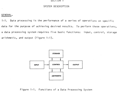
1-1. Data processing is the performance of a series of operations on specific
data for the purpose of achieving desired results. To perform these operations,
a data processing system requires five basic functions: input, control, storage,
arithmetic, and output (figure 1-1).
STORAGE
t
~INPUT ~ CONTROL I - - - OUTPUT
,
t
ARITHMETIC
Figure 1-1. Functions of a Data Processing System
1-2. The input function transmits data to the system by means of several devices,
depending on the desired input media.
1-3.
The storage section retains the data received from the input device unti 1 it is required for operation by other sections of the system.1-4. The arithmetic function handles the actual pr0cessing, or manipulation of
data. This is the computing unit of the system that accomplishes all mathematical
[image:23.613.86.571.73.466.2]1-5. The output function transfers processed results from storage to the output
device{s).
1-6.
The control function directs the flow of data from input to storage, storage to arithmetic, arithmetic to storage, and from storage to output.FUNCTIONAL DESCRIPTION.
1-7. The Burroughs B 5500 Information Processing System is a progressive
depar-ture from the conventional computer system concept, in that it is a
language-oriented system rather than a hardware-language-oriented system.
1-8. Because it is language-oriented, the B 5500 system permits the efficient
compilation and execution of programs coded as problem statements. In fact,
programs which are prepared independently may be processed simultaneously.
1-9. The B 5500 is a modular, high performance, solid state system, designed
to permit users to use efficiently advanced problem-oriented programing
languages. The system consists of truly modular components that provide
flex-ibility in tailoring the system to a wide range of applications.
SYSTEM DESIGN.
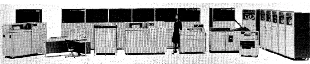
1-10. Figure 1-2 illustrates a typical B 5500 system configuration consisting
of the following components:
NOTE
Figure 1-2 illustrates an average system;
it does not necessarily provide a user1s
B 5280 Processor Module A
B 5283 Input/Output Channel (2)
B 5470 Disk File Control Unit (up to 960 million alphanumeric characters)
B 460 Memory Module (4,096 words, 4 required)
B 122, B 123 or B 124 Card Reader
B 320 or B 321 Line Printer
B 422 or B 423 Magnetic Tape Units (1 required)
Figure 1-2. Typical B 5500 Systems Configuration
1-11. The flexibility of the B 5500 allows it to be expanded at the system
site, in any configuration, up to the specified maximum indicated in table 1-1.
DATA COMMUNICATION SYSTEMS.
1-12. As mentioned, the B 5500 system may be expanded to handle a wide range
of applications. For example, the Burroughs Data Communications Systems can
be incorporated with the B 5500.
1-13. The data communication system, when integrated with the B 5500 provides
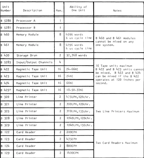
[image:25.617.85.587.265.368.2]Table 1-1
B 5500 Configuratipn Chart
Unit Ability of
Number Description Max. One Unit Notes
B 5280 Processor A 1
B 5281 Processor B 1
B 460 Memory Module 8 4096 words
6 us cycle time B 460 and B 461 modules
cannot be mixed on any
B 461 Memory Module 8 4096 words one system.
4 us cycle time
B 430 Storage Drum 2 32,768 words
B 5283 Input/Output Channels 4
16 Tape units maximum
B 422 Magnetic Tape Unit 16 24-66KC B 422 and B 423 units cannot
be mi xed. B 422 and B 42/-+
B 423 Magnetic Tape Unit 16 24·KC can be mi xed if the B 422
operates at 120 inches per
B 424 Magnetic Tape Unit 16 66KC second.
B 425-k Magnetic Tape Unit 16 IB-50-72KC
B 320 Line Printer 2 475LPM,120chr.
B 321 Line Printer 2 7OOLPM,120chr.
B 325 Line Printer 2 700LPM,132chr. Two Line Printers Maximum
B 328 Line Printer 2 lO40LPM,120chr.
B 329 Line Printer 2 lO40LPM,132chr.
B 122 Card Reader 2 200CPM
B 123 Card Reader 2 475CPtvl
Two Card Readers Maximum
B 124 Card Reader 2 800CPM
B 129 Card Reader 2 1400CPM
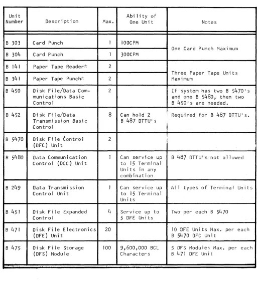
[image:26.615.60.561.136.685.2]Table 1-1 (cont)
B 5500 Configuration Chart
Unit Abi lity of
Number Description Max. One Unit Notes
B 303 Card Punch 1 100CPM
One Card Punch Maximum
B 304 Card Punch 1 300CPM
,.
B 141 Paper Tape Reader";\- 2
Three Paper Tape Un its
B 341 Paper Tape Punch,', 2 Maximum
B 450 Disk File/Data Com- 2 If system has two B 54701 s
munications Basic and one B 5480, then two
Control B 450ls are needed.
Di sk Fi le/Data 8 ~
B 452 Can hold 2 Requi red for B 487 DTTUI s.
Transmission Basic B 487 DTTU's
Contro 1
,
&
B 5470 Disk File Control 2 ~ j
(DFC) Unit
B 5480 Data Communication 1 Can service up B 487 DTTU's not allowed
Control (DCC) Unit to 15 Terminal
Uni t s in any combination
B 249 Data Transmission 1 Can service up A 11 types of Terminal Un its
Control Unit to 15 Terminal
Units
B 451 Disk File Expanded 4 Service up to Two per each B 5470
Contro 1 5 DFE Units
B 471 Disk Fi le Electronics 20 10 OFE Units Max. per each
(DFE) Unit B 5470 OFC Unit
B 475 Oi sk F i 1 e Storage 100 9,600,000 BCl 5 DFS Modu Ie:; Max. per each
(DFS) Module Characters B 471 OFE Unit
..
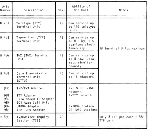
[image:27.615.62.578.133.695.2]Table 1-1 (cont)
B 5500 Configuration Chart
Unit Ability of
Number Description Max. One Unit Notes
~-.-B 481 Teletype (TTY) 15 Can service up Terminal Unit to 399 teletype
units
B 483 Typewriter (TYP) 15 Can service up Terminal Unit to 8 8 493 TIS stations
simul-taneously 15 Terminal Units Maximum
...
B484 TWX (TWX) Terminal 15 Can service up
Unit to 8 AT&T
Data-sets simulta-neously
B 487 Data Transmission 15 Can service up Terminal Unit to 16 adapters
(DTTU)
980 TYP/TWX Adapter 1-TIS or 1-TWX network
981 TTY Adapter 1-TTY network 982 . Data Speed I I Adapter
983 801 Auto Call Un it
984 ul004 Adapter 1-1004 Stat; on 985 IBM 1050 Adapter 25-1050 Stat ions
" " . ' . . . . M . .
-B 493 Typewriter Inquiry 120 Only 8 TIS per each B 483
[image:28.617.40.536.147.587.2]GENERAL.
SECTION 2
SYSTEM EQUIPMENT
2-1. This section describes the operators console and the various peripheral
units used in a B 5500 system. Included in this description are the operating
characteristics, controls, and indicators. Also, procedures for placing the
peripheral units in operation are provided. The following units are discussed:
a. B 5310 Operator Console - with Smith Corona-Marchant Electric
Type-writer (Message Printer).
b. B 122, B 123, B 124 and B 129 Card Reader.
c. B 303 and B 304 Card Punch.
d. B 320, B 521, B 325, B 328 and B 329 Line Printer.
e. B 141 Paper Tape Reader.
f. B 341 Paper Tape Punch.
g. B 421, B 422, B 423, B 424 and B 425 Magnetic Tape Units.
OPERATOR CONSOLE.
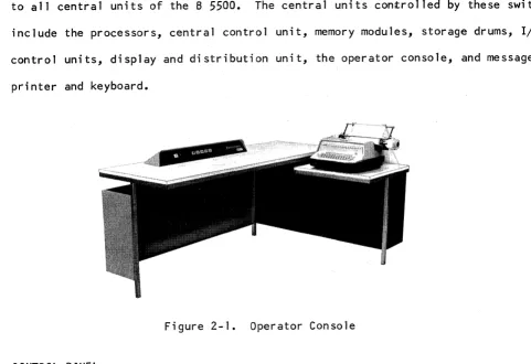
2-2. The operator console contains the message printer as well as the switches
and indicators necessary for directing normal operation of the central units of
the B 5500 system (figure 2-1). The console provides suitable work space for
one operator and includes sufficient surface for the use of operating manuals
2-3. Ihe ROWER ON and POWER OFF switches on the console govern the power supply
to all central units of the B 5500. The central units controlled by these switche
include the processors, central control unit, memory modules, storage drums, I/O
control units, display and distribution unit, the operator console, and message
printer and keyboard.
Figure 2-1. Operator Console
CONTROL PANEL.
2-4. The operator console contains switches and indicators (figure 2-2) to
control the system. The functions of these switches and indicators are
des-cribed in table 2-1.
l
11-="lIIW'""lll
i:
Ji4
U.i!i""
~.
1855oi5]
J
[image:30.613.64.545.130.460.2]Switch/Indicator
HALT
NOT READY
MEMORY CHECK
LOAD
Table 2-1
Operator Console Switches and Indicators
Function
This switch, when pressed, halts processors A and B
after completion of syllables currently in process,
and then lights. It wi 11 remain lit until the LOAD switch
is pressed and a load operation is initiated.
When this indicator lights, it notifies the operator
that one or more units that are part of the system,
and that do not have local Not Ready indicators, have
become a~ai1ab1e for normal use by the system. The
following units are included in this check: core memory
units, I/O control units, magnetic drum storage units,
and message printer keyboard. Other input/output units
are not included. The indicator is not lit by signals
indicating nonavai1ability because of current use with
the system.
This indicator lights whenever the Control State
Processor detects a memory parity error when accessing
core memory.
The LOAD switch is pressed to initially load part of
the Master Control Program into core memory and to
Switch/Indicator
CARD LOAD SELECT
A
NORMAL
A
CONTROL
Table 2-1 (cont)
Operator Console Switches and Indicators
Function
one binary card and to start Processor 1, depending
upon the setting of the CARD LOAD SELECT switch. If
Processor 1 is not idle when this switch is pressed,
the switch will have no effect.
If Processor 1 is idle and the CARD LOAD SELECT switch
is in the drum position (indicator not lit), pressing
the LOAD switch loads 512 words from band 0 of the
drum unit number 1 into core memory starting with cell
16. Control of Processor 1 is then transferred to the
program word in cell 16~ If Processor 1 is idle and
the CARD LOAD SELECT switch is in the card position
(indicator lit), one binary card is read into core
memory locations 16 through
35.
Processor 1 thenaccesses cell 16 and transfers control to this program
word. Card Reader 1 is used.
This indicator lights when Processor A 1S in the Normal
State.
This indicator lights when Processor A 1S in the Control
Table 2-1 (cont)
Operator Console Switches and Indicators
Switch/Indicator Function
8 This indicator lights when Processor 8 is in the Normal
. NORMAL
State.
8
CONTROL
This indicator lights when Processor 8 is in the Control
State.
POWER ON This switch, when pressed, initiates the process of
cycling power on. Power is applied to all units of
the syst~m except the peripheral units. 80th processors
are left idle.
POWER OFF This switch, when pressed, initiates the process of
cycling power off.
MESSAGE PRINTER.
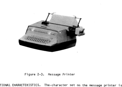
2-5. The message printer and keyboard (figure 2-3) provides the necessary
communi-cation with the central units and the Master Control Program (MCP). Information
regarding the MCP and the user's program (FORTRAN, ALGOL or COBOL) is transferred
through the I/O control unit and translated to the message printer character or
Figure 2-3. Message Printer
2-6. FUNCTIONAL CHARACTERISTICS. The~character set on the message printer is
similar to the character set used on the B 320 and B 321 Line Printers. One
character, the left pointing arrow (~), is excluded from the message printer
character set. The code associated with this symbol is used to indicate the
of-information and must follow the last desired print character. This
end-of-information code, or group mark as it is often referred to, causes termination
of the print operation on the message printer. This code also initiates an
automatic carriage return and line advance. The END-OF-MESSAGE key must be
pressed after each keyboard message entry.
2-7. The characters are printed horizontally at ten-per-inch. Seventy-two
characters are printed per line. Line spacing is selected by the operator and
may be either single or double spacing.
2-8. The character set on the keyboard is arranged as nearly as possible to
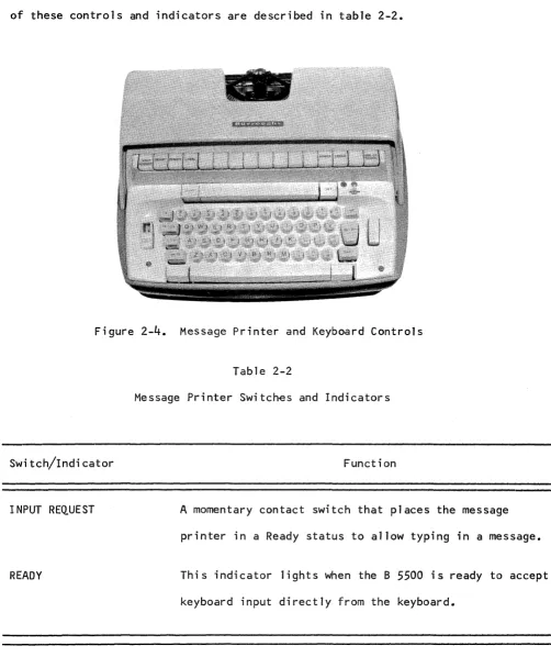
[image:34.613.121.527.79.369.2]2-9. CONTROL PANEL. The message printer and keyboard contains switches and
indicators for contro11ing the operation of the unit (figure 2-4). The function
of these controls and indicators are described in tab1e 2-2.
Figure 2-4. Message Printer and Keyboard Contro1s
Switch/Indicator
INPUT REQUEST
Table 2-2
Message Printer Switches and Indicators
Function
A momentary contact switch that places the message
printer in a Ready status to allow typing in a message.
READY This indicator lights when the B 5500 is ready to accept
[image:35.613.66.568.122.720.2]Switch/Indicator
REMOTE
POWER
ERROR
LOCAL
END OF MESSAGE
B 122 CARD READER.
Table 2-2 (cont)
Message Printer Switches and Indicators
Function
This switch places the keyboard in a remote status, thus
allowing messages to be typed out under control of the MCP.
This indicator lights when power is applied to the unit.
Power is turned on and off by the POWER ON and POWER OFF
switches located on the operator console.
This switch, when pressed, sets a bit in the result
des-criptor ~lagging the MCP that an error occurred during
the typing of the message.
This switch unlocks the keyboard for normal typing. No
communication can occur with the I/O control unit.
This switch, when pressed, terminates the input message,
thus causing a group mark to be transferred as the last
character of the message.
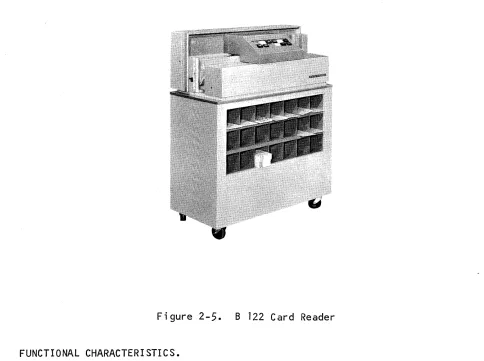
2-10. The B 122 Card Reader (figure 2-5) is capable of reading aO-co1umn punched
cards at a speed of 200 cards-per-minute. The B 122 is controlled by the Input/
Figure 2-5. B 122 Card Reader
FUNCTIONAL CHARACTERISTICS.
2-11. The information punched in an aD-column card is read parallel by bit and
serially by card column. The columns are transferred into an
r/o
channel untilone word of eight characters (alpha mode) or forty-eight bits (binary mode) is
accumulated. When a complete word is accumulated, it is transferred from the
r/o
channel into core memory. This process is repeated until all columns of acard have been read. Upon completion of a card read, the
r/o
channel is releasedto perform the next input/output operation as designated by the Master Control
[image:37.612.66.550.70.431.2]2-12. When reading in alpha mode, the B 122 performs a validity check for each
character punched in the card. If an error is detected, the VALIDITY CHECK
indi-cator will light, a signal is transferred to the B 5500, the error condition is
interrogated by the Master Control Program, and appropriate action is taken by
the system. The VALIDITY CHECK indicator is automatically cleared prior to
execution of a Card Read command. The format of information is controlled by
the card layout and the FORTRAN, ALGOL or COBOL program.
2-13. The card hopper has a capacity of 450 cards, and cards may be placed into
the hopper while the unit is operating as long as approximately 150 cards are
still in the hopper. During loading, the cards in the hopper remain in proper
position for continuous feeding without manual assistance from the operator.
The card stacker also holds a capacity of 450 cards and the cards are stacked
in the stacker in the same sequence as they are fed. Cards should not be removed
from the stacker while the unit is operating.
2-14. The stacker contains an actuator arm that rises as the cards enter the
stacker. When the stacker is at capacity, the arm will be raised sufficiently
to close a switch that will stop the reader. The cards should be removed at
this time.
CONTROL PANEL.
2-15. The B 122 Card Reader control panel (figure 2-6) contains the switches
and indicators for operation of the unit and to indicate error conditions. The
SWitch/Indicator
POWER ON
NOT READY
FEED CHECK
VALIDITY CHECK
~~ ~
~~
L:J
~
EJr-==!
~ RESET
L:J
Figure 2-6. B 122 Card Reader Control Panel
Table 2-3
B 122 Card Reader Control Panel Switches and Indicators
Function
This switch applies power to the B 122 and lights when
pressed •.
This indicator lights when any of the following
condi-tions exist: card jam, stacker full, cover not in place,
empty hopper, STOP switch pressed, read error, or
VALIDITY CHECK indicator lit. The condition causing
the NOT READY indicator to light must be corrected
be-fore processing can be resumed.
This indicator lights when a card jam or a fai lure to
feed or stack a card properly occurs.
This indicator lights when an invalid character is read
by the B 122. The VALIDITY CHECK indicator and its
associated circuitry are always operative on a B 5500
[image:39.612.60.580.79.436.2]Switch/Indicator
. END OF FILE
START
STOP
RESET
VALIDITY ON
READ CHECK
Table 2-3 (cont)
B 122 Card Reader Control Panel Switches and Indicators
Function
This switch is not used on a B 5500 system •
This switch serves two purposes. First, it is used to
condition the B 122 (turn the NOT READY indicator off)
for feeding cards under program control. Second, it
is used to restart the B 122 after an empty hopper has
been reloaded.
This switch is used to stop the B 122 from feeding cards.
When this switch is pressed, the program will halt upon
encountering the next Card Read command unti 1 the START
switch is again pressed.
This switch clears all error indicators on the B 122.
However, the NOT READY indicator is not turned off by
pressing this switch.
This switch-indicator provides a means of performin~ a
validity check. Validity checking is always done on a
B 5500 system.
This indicator lights when the read check circuitry
detects an operational failure. The B 122 is placed
[image:40.617.40.543.33.773.2]Table 2-3 (cont)
B 122 Card Reader Control Panel Switches and Indicators
Switch/Indicator Function
POWER OFF This switch removes power from the B 122.
OPERATING PROCEDURES.
2-16. To place the B 122 Card Reader in operation for reading punched cards,
perform the following procedures:
a. Press the POWER ON switch.
b. Remove all cards from both the hopper and the stacker.
c. Joggle the cards so that all four edges are smooth.
d. Place the joggled cards in the hopper face down, 12 edge toward the
operator with column one of the cards on the left.
e. Press the RESET switch, then the START switch. This wi 11 ready the
card reader so that it may begin reading cards when a request is
received from the B 5500 system.
f. As the file is read, cards may be added to the hopper without stopping
the B 122 providing at least 150 cards remain in the hopper. The
[image:41.613.52.576.60.756.2]2-17. To unload the cards from the B 122 stacker, press the STOP switch, remove
the cards, and press the START switch. The exception to this occurs when the
stacker is full or End-of-Fi1e has been reached and no cards remain in the hopper.
NOT READY CONDITIONS.
2-18. A not-ready condition can occur for several reasons. The # CR* NOT READY
system message on the message printer may indicate that the unit's power has not
been turned on. In addition to this possibility, the conditions which wi 11 cause
a # CRA- NOT READY system message and wi 11 also cause the NOT READY indicator on
the unit to be lit are:
a • Car d j amme d •
b. Stacker full.
c. Cover not in place.
d. Hopper empty.
e. STOP switch pressed.
f. FEED CHECK indicator on ( see paragraph 2 -20) •
g. READ CHECK indicator on (see paragraph 2-19).
h. START switch not pressed.
All not-ready conditions on the unit must be corrected and the RESET switch, then
the START switch must be pressed before the B 5500 can perform another command
using the
B
122.2-19. A read-check condition is handled in conjunction with the # CR* READ CHECK
message for operator intervention. The READ CHECK indicator is lit and the
operator must perform the following:
b. Remove the top card in the stacker and make a visual check of the card.
If the card does not appear to be in satisfactory condition, a new
one should be created.
c. Place the card which was removed from the stacker, or its replacement,
in front of the cards which were removed from the hopper.
d. Place all of these cards that were removed from the hopper, with the
card which was removed from the stacker, in the hopper.
e. Press the RESET switch to clear the READ CHECK indicator.
f. Press the START switch.
g. If the read-check condition persists, refer to the operator's
instruc-tions for the specific program which is affected and/or call the field
engineer.
2-20. A feed-check error can be present when a # CR* NOT READY message is
printed due to a card jam or failure to feed. If this condition prevai Is, the
NOT READY and FEED CHECK indicators are lit and the operator must perform the
instructions in the paragraphs that follow.
2-21. CARD JAM. If a card jam should occur in the B 122 Card Reader because
of cards having a damaged leading edge or sides, the jam is most likely to
occur as a card enters the read station. To clear the jam, perform the fol lowing
procedures:
a. Remove the cover of the card reader control panel. This wi 11 shut down
b. Remove the read head by squeezing the two prongs and lifting' the head
(see figures 2-7 and 2-8).
Figure 2-7. B 122 Card Reader Read Mechanism
Figure 2-8. B 122 Card Reader Read Head Removed
c. Remove the Jammed card(s).
READ HEAD LOCKING PRONGS
d. Replace the read head, making certain that the prongs are released so
that the head locks in place.
[image:44.613.55.537.63.729.2]f. Duplicate the damaged card(s) on a key punch.
g. Remove the cards from the hopper and place the duplicated cards in
front of them.
h. Place the data cards in the hopper.
i. Press RESET, then START on the card reader to continue reading.
2-22. There is a remote possibi lity that a card may jam after passing the read
head, just before going into the stacker. If this should occur, raise the
con-trol panel cover, remove the jammed card, and replace the cover. The read head
does not have to be touched for this type of jam. A card that is jammed at
this point would have been read into the buffer; therefore, the card must not
be replaced in the hopper to be re-read.
2-23. STACKER FULL. If the NOT READY indicator lights because of a full stacker,
remove the cards from the stacker. Press RESET, then START on the card reader
to continue reading.
2-24. COVER NOT IN PLACE. To correct this situation, reset the cover unti 1 it
snaps in place. Press RESET, then START on the card reader.
2-25. EMPTY HOPPER. If the NOT READY indicator lights because of an empty
hopper, reload the hopper and press RESET, then START on the card reader.
2-26. STOP SWITCH PRESSED. If the STOP switch is pressed to stop the card
reader, the NOT READY indicator will light •. To restart the card reader, press
2-27. FEED CHECK INDICATOR LIT. The NOT .READY, indicator .wi 11 light when a card
fails to feed and the FEED CHECK indicator is lit. To correct this situation,
remove the cards from the hopper and examine the bottom card. If the card is
damaged, duplicate the card on a key punch. Place the duplicated card, along
with the other unread cards back into the hopper and press RESET, then START
to resume operation.
2-28. READ CHECK I NDICATOR LIT. The NOT READY i ndi cator wi 11 1 i ght if a read
check condition occurs and the READ CHECK indicator is lit. To correct this
situation, remove the last card from the stacker and place it back in the hopper,
in front of all cards still in the hopper. Press RESET, then START on the
card reader and operation will resume.
2-29. VALIDITY CHECK INDICATOR LIT. The NOT READY indicator wi 11 light if the
VALIDITY CHECK indicator lights because of an invalid character. If this occurs,
and the card is not a control card, the system will cause a # CR* INV CHR IN
COL M message to be typed out. To correct this situation, remove the last card
from the stacker and check it to determine if the punching is correct. If it
is, place the card back in the hopper, in front of all cards sti 11 in the hopper.
Press the RESET switch then the START switch and the card will be read again.
If there are errors in the card that is checked, replace it with a corrected
card and proceed as described above.
OPERATOR MAINTENANCE.
2-30. Among other operational duties, the operator is responsible for:
a. Inspecting cards for acceptable condition before loading the hopper
and after removal from the stacker.
c. Removing occasional card jams (the operator should clear a jam within
two minutes).
d. Assuring that cards have been stored in a manner consistent with
specifications.
e. Making up missing or damaged cards.
f. Keeping records of all card reader fa; lures.
g. Checking cards against a standard commercial gauge for punch
registra-tion when errors occur with a card.
h. Analyzing all stoppages to a point where side panels must be removed.
i. Removing foreign material from the card path once every eight-hour
shift.
j. The following should be cleaned by the operator every eight hour
shift:
1) Remove the exciter lamp assembly and clean the solar cell apertures,
the feed bed, and the hopper area with a soft bristle brush (camel
hair or simi lar).
2) Freon is the only cleaning agent that should be used on the solar
cell assembly. It should be applied with a soft cloth or camel
hair brush. Alcohol or other cleaning agents may cause damage to
the potting in the assembly.
B 123/B 124/B 129 CARD READERS.
2-31. The B 123, B 124, and B 129 Card Readers are physically identical and
differ only in their operating speeds. That is, the B 123 is designed to
operate at speeds up to 475 cards-per-minute. The B 124 operates at aOO
cards-per-minute, while the
B
129 operates at a speed of 1400 cards-per-minute. Since the difference between the three card readers is only one of operatingspeed, only the B 124 will be described in detail in this
manual.-B 124 CARD READER.
2-32. The B 124 Card Reader (figure 2-9) has the capacity of reading aO-co1umn
punched cards at a rate of 800 cards-per-minute. Fifty-one, sixty, and
sixty-six column cards may also be read. The B 124 is controlled by the B 5500 system
I/O
control unit and transfers one aD-column card into memory every 75 milliseconds. [image:48.613.83.505.406.740.2]2-33.
The punched cards used on the B124
Card Reader must be3.25
inches wideand between
0.007
and0.009
inch thick. Any file of cards read6n the B124
must be consistent in thickness and length. For example, all cards in a
parti-cular file must be
80
columns(7.375
inches), or66
columns(6.157
inches), or60
columns(5.635
inches), or51
columns(4.852
inches) in length. Cards ofvariable lengths or thicknesses must not be intermingled in a file that wi 11 be
process~d on the B
124.
FUNCTIONAL CHA.RACTERISTICS.
2-34.
The information punched in the card is read by the 8124
seriallycolumn-by-column. The information is moved a column at a time until eight characters or
48
binary bits are accumulated; the information is then transferred from the I/Ocontrol unit into core memory.
2-35.
The accumulation process by the I/O control unit is repeated until allcolumns have been read and transferred to core memory. When a card has been
read, the I/O control unit is free to execute the next assigned input/output
function.
2-36.
During a read operation, a validity check is performed as each characteris read. The VALIDITY CHECK indicator lights on the control panel of the B 124
and a signal is transferred to the B
5500
system when this is detected. Thecondition is sensed by the Master Control Program and if the card is not a
con-trol card, the #CR* INV CHR IN COL n message is typed out. After the card is
corrected, the card will be re-read and processing resumed. All formatting of
information is controlled by the card layout and the ALGOL, FORTRAN or COBOL
2-37. The card hopper has a capacity of JqOO.:caF~s,an9 c;:an:be.l,oCldedby the
operator whi Ie the uni t is operating. ,Tbe operator doesnpt have to hold thpse
cards already in the hopper in position when loading additional cards •. Card,s
are conveyed from the hopper to the card stacker by m~ans of a card transport
mechanism. Failure to feed a card will cause a missing,card condition. The
B 124 will be placed in a Not.Ready state and the #CR* NOT READY message wiJl
be typed out. A card jam will not cause mechanical damage. The unit will stop
when no more than two cards are jammed (perhaps three in the B 129). The cards
are stacked in the card stacker in the same sequence and manner in which they
were fed. The stacker will hold a maximum of 3000 cards. Cards may be removed
from the stacker during operation without holding the remaining cards in position.
CONTROL PANEL.
2-38. The B 124 Card Reader contains a control panel (figure 2-10) for operating
the unit and to indicate error conditions. The function of each switch and
indicator on the control panel is provided in table 2-4.
I
PO,WER ONI
~
OT
-READY
' - - _ - - l
[ ,ow'" [ Off
Switch/Indicator
Table 2-4
8 124 Card Reader Control Panel Switches and Indicators
Function
--~---.--.-'-' .. "" .. -....•..
-
.. -~".-.. ,.---_._--->.,,-_. __ ..
. ----.---~.~---..
-
..-
.. -.,,-~,,- .... -_._---POWER ON This is a switch-indicator that applies power to the
8 124, lighting when pressed.
NOT READY Thi s indicator lights when anyone of the following
conditions exists: card jam, stacker full, cover not
in place, empty hopper, STOP switch pressed, START
switch not pressed, read error, VALIDITY CHECK
indi-cator lit, or FEED CHECK indiindi-cator lit. The condition
causing the NOT READY indicator to light must be
corrected before processing can be resumed.
FEED CHECK This indicator lights as a result of a card jam or a
failure to feed or stack a card properly.
VALIDITY CHECK This indicator lights when an invalid character is
read by the 8 124. The VALIDITY CHECK indicator and
its associated circuitry are always operative on a
8 5500 system.
START This switch serves two purposes. First, it is used to
condition the 8 124 card reader (turn the NOT READY
indicator off) for feeding cards under program control.
Second, it is used to restart th e 8 124 after an
[image:51.613.53.561.100.725.2]Swit~h/Indicator
STOP
RES~T
VALIDITY ON
READ CHECK
POWER OFF
OPERATING PROCEDURES.
Table 2~4 (cont)
B 124 Card Reader tontrol Panel Switches and Indicators
Function
This switch stops the B 124 from feeding cards; When
the switch is pressed, the #CR* NOT READY message is
printed out.
This switch clears all error indicators on the B 124.
However, the NOT R~ADY indicator is not turned off
by pressing this switch.
This switch-indicator provides the means of performing
a validity check. Validity checking is always
per-formed on a B 5500 system.
This indicator lights when the read check circuitry
detects an operational failure. The B 124 is placed
in a Nat Ready state and the #CR* READ CHECK message
is printed out.
This switch removes power from the B 124.
2-39. Before cards can be processed by the B 12~ Card Reader, it is necessary
to prepare the feeder hopper and the stacker to handle the size card desired.
[image:52.613.29.566.64.698.2]The width of the hopper and the stacker is adjustable to accommodate either 51-,
60-, 66-, or 80-column cards. This adjustment is performed by altering the
position of the front wall of each area. In addition, it iS91~pnecessary to
adjust the position of the stacker tire and bumper assemblY~'ld ~~he stacker
follow block. For example, if 80-column cards are to be processed, the operator
would perform the following procedure:
a. Press the stacker follow block latch release and move the block up
or down to the line marked 80.
b. Press the release button on the stacker tire and bumper assembly and
STACKER TIRE AND BUMPER ASSEMBLY
RELEASE BUTTON
STACKER FRONT WALL HOLDING SCREW
position it to 80 on the card size marker provided on the end plate of
the assembly (see figure 2-11).
STACKER BUMPER
[image:53.618.62.556.257.733.2]STACKER FRONT WALL
Figure 2~ll.
STACKER TIRE
Stacker End Plate Assembly
STACKER GEAR
STACKER PHOTO CELL
c. Loosen the two holding screws on the stacker front wa11.
d. Press down on the two screws simu1taneous1y and move the wa11 to the
80 position indicated by the card size marker in the f100r of the
stacker (see figure 2-12).
Figure 2-12. Adjusting Stacker Front Wa11
e. Re1ease the two holding screws and tighten them.
f. Steps c and d can be followed when adjusting the feeder hopper front
wa1l.
2-40. The B 129 has a slightly different construction in the stacker bumper area.
This bumper assembly can be moved by pulling up on the assembly and disengaging
it from the stacker guide assembly. The key-hole type slots in the guide will
[image:54.617.57.462.51.684.2]2-41. If 51-, 60-, or 66-co1umn cards are to read, the removable stacker gear
should be removed from the stacker. This is accomplished by pressing down on
the gear, turning it counterclockwise, and then pulling up. To replace the gear,
insert it in the hole, press down, and then turn it clockwise.
2-42. When the above procedures have been completed, the card reader is ready
for loading and reading of punched cards. At the start of an operation, the
feeder hopper flag wi 11 be at the extreme left of the hopper. To load and
read punched cards, proceed as follows:
a. If the entire system is off, press the operator console POWER ON switch.
This will apply power to the system. If only the card reader IS off,
press the card reader POWER ON switch.
b. Grasp the follow block, pulling it to the right and up and out of the
hopper.
c. With the left hand, place the deck of punched cards in the hopper,
Column 1 at the top, holding them loosely to allow the vibrating base
to joggle them so that all four corners are even.
d. Hold the cards against the feeder belt with the left hand and lower the
follow block into the hopper, allowing it to move to the left and
Figure 2-13. Loading Cards
NOTE
When inserting the follow block into the hopper,
always maintain a grip on it until it is flush
against the card deck.
e. Press RESET, then START on the card reader. This will ready the card
reader so that it may read cards when a command is received from the
B 5500 system.
2-43. To load additional cards into the hopper while the unit is operating,
pro-ceed as follows:
a. Place the punched cards in the hopper (column 1 at the top), holding
them loosely to allow the vibrating base plate to joggle them so that
b. Slide the cards to the left until they are against the back of the
hopper follow block. Hold the cards in this position with th~ left
hand$
c. With the right hand, raise the follow block up and out of the hopper
and move it to the right until it is past the last card in the deck.
d. Lower the follow block back into the hopper and allow it to move to
the left until it is pressed against the card deck.
NOTE
When loading additional card decks into the hopper,
always maintain a slight amount of pressure on the
cards, especially when removing the follow block
from between both groups of cards. Otherwise,
misfeeding may occur.
2-44. Improper feeding of cards can result from improper adjustment of the
separator block. To correct this condition, proceed as follows:
a. Press POWER OFF switch.
b.
Raise the cover of the transport system.c. Remove any cards that are in the feeder hopper.
d. Loosen the knurled thumb screw.
f. Adjust the knurled adjustment knob at the right side of the assembly
" , "
until the card fits snugly between the ~eederbelt and the s~parator
block. (This is a judgement adjustment by the operator and will become
quite easy with experience.)
g. Tighten the knurled thumb screw.
h. Close the cover of the transport system.
i. Press the POWER ON switch.
2-45.
When the last card has been read from the feeder hopper an~ more cardsare to be processed, #CR* NOT READY message will be printed out. Insert the
cards into the hopper as outlined in paragraph
2-40.
Pressing the START switchwill resume operation.
2-46.
The cards that have been read can be removed from the stacker at any timethe operator so wishes. To remo~ cards while the unit is operating, proceed as
follows:
a. Grasp the stacker fo110w block with the right hand.
b. With the left hand, grasp a group of cards.
c. Raise the cards out of the hopper, while at the same time, maintain a
slight amount of pressure against the remaining cards in the stacker
with the cards being removed.
d. Move the follow block to the left so that it will press against the
cards in the stacker as soon as the cards being removed have cleared