01036–08
D25086 WRONG
CORRECT
D25087 Looseness of Crimping
Core Wire
Terminal Deformation Pull Lightly
ELECTRONIC CIRCUIT INSPECTION PROCEDURE
1. BASIC INSPECTION
(a) RESISTANCE MEASURING CONDITION OF ELECTRONIC PARTS
(1) Unless stated, all resistance is measured at an ambient temperature of 20C (68F). As the re-sistance may be outside the specifications if measured at high temperatures immediately after the vehicle has been running, measurements should be made when the engine has cooled down.
(b) HANDLING OF CONNECTOR
(1) When removing the connector with lock, press the connector in the direction of the engagement and remove the lock by lightly pressing the lock claw. (2) When removing the connector, do not hold the
har-ness, but hold the connector.
(3) Before connecting the connector, check that there is no deformation, damage or missing terminals. (4) The connector with a lock should be securely
con-nected until it makes a ”click” sound.
(5) When checking the connector with a Toyota electri-cal tester, check it from the backside (harness side) of the connector using a mini test lead.
NOTICE:
As a water proof connector cannot be checked from the backside, check by connecting the sub–harness.
Do not damage the terminals by moving the inserted tester needle.
(c) CONNECTOR CHECKING POINTS
(1) Checking when the connector is connected: By holding the connector, check the inserted condi-tion and locking efficiency (engaged condicondi-tion).
(2) Checking when the connector is removed:
Check by lightly pulling the wire harness (missing terminal, terminal crimping condition, core wire break).
Check visually for any rust, metal particles, water and bent terminals (rust, mixing of foreign object, terminal deformation).
NOTICE:
D25088 Same terminal as
a male terminal
D20024 WRONG CORRECT
D01557 WRONG
C Sensor
OPEN 1 2
B 1 2
1 2
1 2 A Fig. 1
ECU
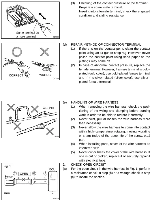
(3) Checking of the contact pressure of the terminal: Prepare a spare male terminal.
Insert it into a female terminal, check the engaged condition and sliding resistance.
(d) REPAIR METHOD OF CONNECTOR TERMINAL (1) If there is on the contact point, clean the contact
point using an air gun or shop rag. However, never polish the contact point using sand paper as the platings may come off.
(2) In case of abnormal contact pressure, replace the female terminal. However, if a male terminal is gold– plated (gold color), use gold–plated female terminal and if it is silver–plated (silver color), use silver– plated female terminal.
(e) HANDLING OF WIRE HARNESS
(1) When removing the wire harness, check the posi-tioning of the wiring and clamping before starting work in order to be able to restore it correctly. (2) Never twist, pull or loosen the wire harness more
than necessary.
(3) Never allow the wire harness to come into contact with a high–temperature, rotating, moving, vibrating or sharp (edge of the panel, tip of the screw, etc.) part.
(4) When installing parts, never let the wire harness be interfered with.
(5) Never cut or break the cover of the wire harness. If one is cut or broken, replace it or securely repair it with electrical tape.
2. CHECK OPEN CIRCUIT
[image:2.595.35.555.68.761.2]Z17005 Fig. 2
Sensor
C B A
ECU 1
2
1
2 2
1
B04722 Fig. 3
Sensor
B2 A
1 2
1
2 2
1
C B1
1 2
ECU
Z17007 Fig. 4
Sensor
C B A
1 2
1
2 2
1 5V
5V 0V
(b) Check the resistance.
(1) Disconnect connectors A and C and measure the resistance between them.
Resistance: 1 Ω or less
HINT:
Measure the resistance while lightly shaking the wire harness vertically and horizontally.
In the case of Fig. 2:
Between terminal 1 of connector A and terminal 1 of connector C → 10 KΩ or higher
Between terminal 2 of connector A and terminal 2 of connector C → Below 1 Ω
Therefore, the cause is an open circuit between ter-minal 1 of connector A and terter-minal 1 of connector C.
(2) Disconnect connector B and measure the resis-tance between the connectors.
In the case of Fig. 3:
Between terminal 1 of connector A and terminal 1 of connector B1 → Below 1 Ω
Between terminal 1 of connector B2 and terminal 1 of connector C → 10 KΩ
Therefore, the cause is an open circuit between ter-minal 1 of connector B2 and terter-minal 1 of connector C.
(c) Check the voltage.
(1) In a circuit in which voltage is applied (to the ECU connector terminal), an open circuit can be checked by conducting a voltage check.
As shown in Fig. 4, with each connector still con-nected, measure the voltage between the body ground and terminal 1 of connector A at the ECU 5 V output terminal, terminal 1 of connector B, and terminal 1 of connector C, in that order.
(2) If the results are:
5 V: Between terminal 1 of connector A and body ground
5 V: Between terminal 1 of connector B and body ground
0 V: Between terminal 1 of connector C and body ground
Z17008 C SHORT
1 2
B 1 2
1 2 A Fig. 5
Z17009 Fig. 6
Sensor
C B A
ECU 1
2
1
2 2
1
Z17808 Fig. 7
Sensor
B2 A
1 1 1
C B1
1
ECU
2 2 2 2
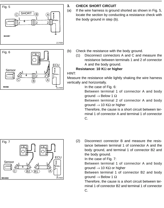
3. CHECK SHORT CIRCUIT
(a) If the wire harness is ground shorted as shown in Fig. 5, locate the section by conducting a resistance check with the body ground in step (b).
(b) Check the resistance with the body ground.
(1) Disconnect connectors A and C and measure the resistance between terminals 1 and 2 of connector A and the body ground.
Resistance: 10 KΩ or higher
HINT:
Measure the resistance while lightly shaking the wire harness vertically and horizontally.
In the case of Fig. 6:
Between terminal 1 of connector A and body ground →Below 1 Ω
Between terminal 2 of connector A and body ground →10 KΩ or higher
Therefore, the cause is a short circuit between ter-minal 1 of connector A and terter-minal 1 of connector C.
(2) Disconnect connector B and measure the resis-tance between terminal 1 of connector A and the body ground, and terminal 1 of connector B2 and the body ground.
In the case of Fig. 7:
Between terminal 1 of connector A and body ground →10 KΩ or higher
Between terminal 1 of connector B2 and body ground →Below 1 Ω
[image:4.595.39.562.60.723.2]IN0383
Example
Ground
IN0384 Ground
ECU Side
W/H Side
Ground
4. CHECK AND REPLACE ECU NOTICE:
Start an inspection of the connector from the back-side of the connector on the wire harness back-side with the connector connected to the ECU.
When no measurement condition is specified, per-form the inspection with the engine stopped and also the ignition switch ON.
(a) First check the ECU ground circuit. If it is faulty, repair it. If it is normal, the ECU could be faulty. In this case, re-place the ECU with one that functions normally and check if the symptoms appear.
(1) Measure the resistance between the ECU ground terminal and body ground.
Resistance: 1 Ω or less