Figure 1 Cross-flow ultrafiltration. Particles in the feed that are larger than the rated pore size of the membrane are retained in the retentate stream while smaller particles pass through into the permeate. (Adapted from Cheryan (1998) with permission from Technomic.)
(eds)Preconcentration Techniques for Trace Elements, pp. 301}331. Boca Raton: CRC.
Cox JA and Twardowski Z (1980) ElectricReld enhance-ment of Donnan dialysis. Analytical Letters 13(A14): 1283}1291.
Dasgupta P (1988) Approaches to ion chromatography. In: Tarter JG (ed.) Ion Chromatography, pp. 191}338. New York: Marcel Dekker.
JoKnson AJ, LoKvkvist P, Audunsson G and Nilve G (1993) Mass transfer kinetics for analytical enrichment and sample preparation using supported liquid membranes in aSow system with stagnant acceptor liquid.Analytica Chimica Acta277: 9}24.
Robinson T and Justice JB (1991) Microdialysis in the Neurosciences. New York: Elsevier Science.
Spohn U, Eberhardt R, Joksch B,et al. (1991) Enzymatic multichannel-FIA methods for on-line fermentation monitoring and control. In:GBF Monograph, vol. 14, pp. 51}62. Weinheim: Verlag Chemie.
Stec RJ, Koirtyohann SR and Taylor HE (1986) Preconcentration of trace elements from aqueous solutions by osmosis.Analytical Chemistry58: 3240} 3242.
Valcarcel M and Luque de Castro MD (1991) Non-chromatographic Continuous Separation Techniques. Cambridge: Royal Society of Chemistry.
Ultra
\
ltration
M.Cheryan, University of Illinois, Urbana, IL, USA
Copyright^ 2000 Academic Press
Introduction
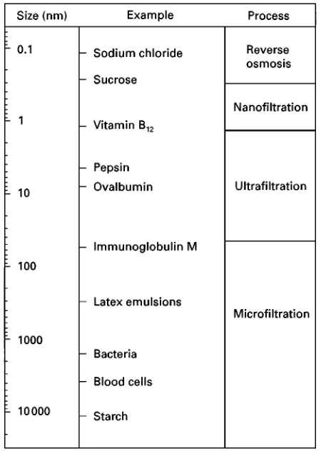
UltraRltration (UF) is aRltration process that employs a membrane to fractionate liquid mixtures containing molecules that range in size from about 1000 daltons in molecular weight to 500 000 daltons. The mem-brane, made of either polymeric or inorganic mat-erials, is a semipermeable barrier containing pores of a certain size distribution that are used to retain or ‘reject’ components of the feed mixture that are larger than the rated pore size while allowing molecules that are smaller than the pores to pass through the mem-brane. This separation process is very simple (Figure 1) involving only the pumping ofSuids. The membrane is assembled in a particular conRguration and placed in a module, and the feed stream is pumped through the module over the membrane sur-face in a cross-Sow mode. The pressure forces solvent
(e.g. water) and solute molecules smaller than the pores on the membrane surface through the mem-brane into the ‘permeate’ stream while larger solutes are rejected and retained in the ‘retentate’ stream. The retentate is recycled through the module until the required degree of puriRcation, separation or concen-tration is achieved.
UltraRltration is similar in concept to other pres-sure-driven membrane processes such as microR ltra-tion, nanoRltration and reverse osmosis. However, as shown inFigure 2, the size range of the solutes that are retained by each membrane is different. Reverse osmosis (RO) membranes are designed to retain all components except for the solvent (e.g. water). It is essentially a concentration process. Owing to the osmotic pressure of the solutes retained by RO mem-branes, pressures needed to operate RO systems are typically 30}60 bar (450}900 lb in\2). NanoR ltra-tion (NF) membranes have slightly larger pores and are designed to allow monovalent salts such as sodium chloride to pass through, but retains divalent salts, disaccharides and dissociated organic acids. Pressures are usually lower, about 15}25 bar.
Micro-Rltration (MF) membranes retain components that are in suspension or in colloidal form, and is essential-ly a clariRcation process. Pressures are usually 1}4 bar.
Figure 2 Examples of compounds of various sizes separated by different membranes. (Adapted from Cheryan (1998) with permission from Technomic.)
no change in phase of the solvent and thus energy consumption is much lower. Being a nonthermal pro-cess, there are no extremes of temperature and feed solutions can be concentrated by UF with little or no thermal damage to heat-sensitive components. Since pores are large enough to allow passage of soluble salts, acids and alkalis, the microenvironment of the solution remains largely unchanged during the process.
There are several factors that affect
ultra-Rltration applications: the membrane material, properties of the membrane, process engineering parameters, design of the membrane module, fouling and cleaning and process design. The most important performance parameters in UF areSux and rejection. Flux is the volume of permeate per unit time per unit membrane area. Higher Sux means lower capital and operating costs. Rejection is a measure of a membrane’s separating capabilities. It is deRned as:
1!Concentration of solute in the permeate Concentration of solute in the retentate
Membrane Material
Membranes have been made from over 150 different polymers or inorganic materials, but only about a dozen have achieved widespread commercial use for UF. The most common are polymers such as polysulfone, polyethersulfone, polyvinylidene S uor-ide, polyacrylonitrile, cellulose acetate and regen-erated cellulose as well as inorganic materials such as alumina, zirconia and titania. Most polymeric UF membranes are asymmetric in structure, i.e. they have a thin ‘skin’ 0.1}0.2m thick on the sur-face of the membrane. This skin contains the pores of the required size and determines the separation characteristics of the UF membrane. Polymer layers under the skin usually consist of voids which support the skin layer. The skin and void layer are one struc-ture and one polymer when made by a phase-inver-sion process, but they could be two or more different polymers in composite membranes. The membrane is then laid on a backing such as polyester or polypropy-lene and then formed into the module. In some cases, such as hollowRbres, a concentrated solution of the polymer is spun or extruded to form self-supporting single polymer hollow tubes with the pores on the inside surface of the tube.
Inorganic membranes have considerably widened the range of membrane applications, particularly in food processing, waste treatment, recovery of chem-icals and biotechnology applications, where high temperature, acid and/or alkali stability, steam steril-izability and cleanability are important. A macropor-ous substrate of aRne dispersion of the powder isRrst formed, e.g. by thermal sintering of an extruded paste of the powder. If a tubular geometry is used, pastes from two powders of different grain sizes may be co-extruded, with theRner grain being closer to the axis. After baking at high temperatures ('10003C), the inside may be coated by slip casting with theRnal
Rne grain powder. A series of such layers may be necessary to obtain the asymmetric-type ultrastruc-ture. The membrane isRnally set by a series of press-urizing, drying and baking steps. The most common ceramic materials are-alumina, zirconia and titania. Composites of zirconia or titania membranes on alumina, carbon or stainless-steel supports are available.
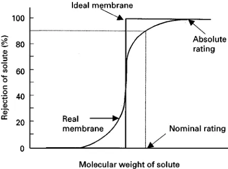
Figure 3 Typical molecular-weight profile of ideal and real membranes. Relationship shown is between molecular size of a solute in the feed stream and rejection of the solute by the membrane. (Adapted from Cheryan (1998) with permission from Technomic.)
8}12 m2 per module. Normal process ratings are 15 bar and 1503C.
Inorganic membranes have several desirable prop-erties. They are inert to common chemicals and sol-vents and have wide temperature limits. Depending on the seals and type of housing, some inorganic membranes can be operated as high as 3503C and within wide limits of pH from 0.5 to 13.5. The biggest advantage is their extended operating life-times. Operating life of membranes is most affected by the frequency and nature of the cleaning regime. In contrast to polymeric membranes which typically have 9}18-month lifetimes with normal daily clean-ing cycles, inorganic membranes are able to tolerate frequent aggressive cleaning regimes. Many are still operating 10}14 years after installation with theRrst set of membranes. One major limitation is that they are 10}30 times more expensive than polymeric membranes.
Membrane Properties
Pore size is the most important property of a UF membrane. Pores can be visualized using electron microscopy. Surface porosity (the proportion of the membrane surface occupied by pores) is less than 10% for many UF membranes. In an ideal membrane, all pores should be of the same size. In reality, there is a distribution of pore sizes, as shown inFigure 3. This makes it difRcult to get a sharp separation of similarly sized molecules by UF. A common method to charac-terize UF membranes is to challenge the membrane with several macromolecules of known molecular sizes. Since proteins of different molecular weights are usually used as molecular markers, UF mem-branes are characterized in terms of their ability to retain proteins of a particular molecular weight. Fig-ure 3 is a graphical representation of solute rejection data for ideal and real membranes. No membrane will display the sharp pore-size distribution shown for the ideal membrane. MF membranes are given ‘absolute’ ratings which is the largest particle that will be retained by the membrane, based on actual tests under standard conditions. In contrast, UF mem-branes are given ‘nominal’ ratings which refer to the molecular weight of a test solute (ideally it should be a globular protein) which is 90% rejected by the membrane under standard conditions. This rating is termed the molecular weight cut-off (MWCO) of the membrane.
Proteins are not ideal compounds to use for this purpose, since their molecular size can be affected by pH, ionic strength and interactions with buffer com-ponents. Proteins can have different isoelectric points, solubility and hydrophobicity, thus causing
them to interact with and foul the membrane to different extents, which affects measured rejections. In addition, proteins which differ by 10 times in MW may only differ by three times in size in their globular form. Owing to the difRculty ofRnding proteins that are sufRciently pure (and inexpensive) to conduct MWCO evaluations, other compounds such as poly-ethylene glycols (PEG) and dextrans have been used because they are water soluble and can be readily obtained with well-deRned and narrow-size distribu-tions. Since the shapes of these various compounds are different, the MWCO proRle of a membrane will also differ depending on the solute test marker used. Environmental conditions such as pH and ionic strength also affect shape and conformation of mol-ecules which can affect rejection.
Figure 4 Effect of operating conditions on flux of an ultrafiltra-tion system. (Adapted from Cheryan (1998) with permission from Technomic.)
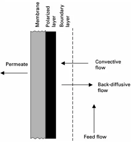
Figure 5 Concentration polarization in ultrafiltration. dynamic membrane on the original membrane that
inhibits passage of the smaller molecule. Operating conditions that change the shape or conformation of the solute will also affect its rejection.
As a general rule, fractionation of polymers can be accomplished if there is at least a 10-fold difference in molecular weight. Separation of similarly sized mac-romolecules can be enhanced by diluting the feed to minimize solute}solute interactions and solute-membrane interactions.
Other factors affecting separation are operating parameters such as pressure and cross-Sow rate. These control the degree of turbulence and the thick-ness of the boundary layer and extent of concentra-tion polarizaconcentra-tion (deRned below), which in turn affect permeability of smaller solutes.
Operating Parameters
[image:4.568.54.277.522.672.2]Separation of solutes by UF membranes occurs by a sieving mechanism. The transport ofSuids through the pores is modelled as laminarSow through chan-nels, withSux directly proportional to applied trans-membrane pressure. However, it has frequently been observed that under certain operating conditions,Sux becomes independent of pressure as shown in
Figure 4. This is owing to ‘concentration polariza-tion’ which is shown inFigure 5. Molecules or par-ticles that are partially or completely retained by the membrane accumulate on the surface of the mem-brane during ultraRltration. This build-up of solids will cause a concentration gradient within the bound-ary layer, resulting in back-transport of solute into the bulk stream owing to diffusion. Eventually a steady state is reached where the two phenomena balance each other. Solute concentration reaches a maximum at the ‘gel concentration’. This
con-solidated gel layer is the reason that pressure indepen-dence in Figure 4 is observed. Flux is no longer con-trolled by pressure but by the mass-transfer charac-teristics of the system which in turn depends on the diffusion coefRcient of the rejected molecules in the boundary layer, turbulence in theSow channel, viscosity and density of theSuid stream. Higher tem-peratures lead to higherSux because of its favorable effect on diffusivity and viscosity. In the pressure-independent region,Sux decreases in a semi-logarith-mic manner with bulk feed concentration and in-creases with higher turbulence (usually achieved by higherSow rates through the module).
Module Design
Figure 6 Schematic of ultrafiltration membrane modules: tubular, plate and spiral-wound.
Table 1 Applications of ultrafiltration Food industry
Concentration of protein and fat for cheese manufacture; fractionation of cheese whey for whey protein concentrates; clari-fication of fruit juices (apple, apricot, citrus, cranberry, grape, peach, pear, pineapple; gelatin concentration and de-ashing; eggs concentration and reduction of glucose; animal blood concentration; soybean protein concentrates and isolates; clarifi-cation of protein hydrolysates; vegetable oils (degumming, deacidification, bleaching, removal of metals, dewaxing; clarifying frying oils); sugar refining; dextrose clarification; alcoholic beverages
Chemicals and wastewater
Electrocoat paint; oily wastewater; stillage from bioethanol plants; caustic and acid recovery; brine recovery; printing ink; laundry wastewater; textile industry; latex emulsions; pulp and paper industry; tanning and leather industries; fish processing; poultry industry
Biotechnology
Separation and harvesting of microbial cells; enzyme recovery; affinity ultrafiltration; membrane bioreactors
high pressure drops for pumping and require the use of modules that can withstand high pressures, elimin-ating most hollow Rbre/capillary modules. On the other hand, these modules have extremely high pack-ing densities (surface area : volume ratios) and com-paratively low energy consumption, making them useful in applications where the feed is of relatively low viscosity and low in suspended matter.
Spiral-wound modules and some plate modules in-corporate a spacer in the feed channel to keep the membrane sandwich apart. This spacer can add con-siderable turbulence to the Suid Sow and thus in-crease the Sux. However, this spacer causes a para-sitic drag and creates dead spots in the feed channel, which can cause suspended particles to block theSow channel, resulting in high pressure and cleaning prob-lems.
Fouling and Cleaning
Fouling manifests itself as a decline inSux with time under constant operating conditions. The sieving properties of the membrane may also change. This is owing to irreversible interactions between feed com-ponents and the membrane, causing a layer of foulant on the membrane, blinding of the pores and an in-creased resistance to Suid Sow through the mem-brane. Many membrane materials listed earlier are relatively hydrophobic (e.g. polysulfone, poly-vinylidene Suoride) and tend to foul more than hydrophilic membrane materials (e.g. cellulosics,
cer-amics). Many feed components interact strongly with membranes, e.g. oils through hydrophobic interac-tions with hydrophobic membranes, proteins by hy-drogen bonding, charge interactions or hydrophobic interactions, and salts by precipitation or charge in-teraction.
A fouled membrane has to be cleaned according to the nature of the foulant. Proteins can be effectively cleaned with alkaline solutions, salts are removed with acid cleaners. The quality of the water is very important in ensuring a membrane can be effectively cleaned in the shortest time possible.
Flux can be enhanced by periodic backwashing, pulsatingSows, uniform transmembrane pressure or co-current permeate Sow techniques. These have been found to be effective in maintaining highSuxes with feed streams containing colloidal or suspended matter and less effective with foulants that are in solution.
Applications of Ultra
\
ltration
of proteins and other macromolecules. Continued advances in membrane science and manufacture and engineering improvements to modules and systems will allow a greater penetration of this technology in a variety of industries in the future.
See also: II/Membrane Separations: Filtration; Micro-filtration.
Further Reading
Bhave RR (ed.) (1991) Inorganic Membranes. Synthesis, Characteristics and Applications. New York: Van Nos-trand Reinhold.
Cheryan M (1998) UltraTltration and MicroTltration Handbook. Lancaster, PA: Technomic.
Cheryan M and Alvarez J (1995) Membranes in food pro-cessing. In: Noble RD and Stern SA (eds) Membrane
Separations. Technology,Principles and Applications, p. 415. Amsterdam: Elsevier.
Cheryan M and Rajagopalan N (1998) Membrane treatment of oily streams. Wastewater treatment and waste reduction. Journal of Membrane Science 151: 15}38.
Ho WSW and Sirkar KK (eds) (1992)Membrane Hand-book. New York: Chapman and Hall.
Hsieh HP (1996)Inorganic Membranes for Separation and Reaction. Amsterdam: Elsevier.
Lloyd DR (ed.) (1985)Materials Science of Synthetic Mem-branes. Washington, DC: American Chemical Society. Matsuura T (1994)Synthetic Membranes and Membrane
Separation Processes. Boca Raton, FL: CRC Press. Mulder M (1991)Basic Principles of Membrane
Technol-ogy. Norwell, MA: Kluwer Academic Publishers. Singh N and Cheryan M (1998) Membrane technology in
corn reRning and bio-products processing. Starch/ Sta(rke50: 16}23.
PARTICLE SIZE SEPARATION:
Electric Fields in Field Flow Fractionation
See II / PARTICLE SIZE SEPARATION / Field Flow Fractionation: Electric Fields
PARTICLE SIZE SEPARATION
Electrostatic Precipitation
J. J. Harwood, Tennessee Technological University, Cookeville, TN, USA
Copyright^ 2000 Academic Press
Introduction
Electrostatic precipitators (ESPs) are the most com-monly used devices for the removal ofRne particles in exhaust from industrial and utility processes. Wire-plate ESPs consist of three or more sections of arrays of large (e.g., 15 m;5 m), grounded metal collector plates between which are situated wire or other nar-row, high voltage electrodes (Figure 1). Less com-monly, a wire-cylinder electrode conRguration is used. Particles entering the Rrst section are quickly charged by ions generated by the plasma coronas around the wires. (Current does pass between the
electrodes, hence the term ‘electrostatic’ is not really accurate, but indicates the small current-to-electrode area.) The charged particles are drawn toward and deposit upon the collector plates, which are period-ically cleaned by mechanical ‘rapping’. This method is very efRcient in removing particles in the 1}'10m range. The most common use of ESPs is in control of exhaust from coal combustion utilities. Precipitators are also used in the cement, ore smelt-ing, steel production, pulp and paper manufactursmelt-ing, and chemical processing industries, and in waste combustion utilities. Small units are used in cleaning domestic and workplace air, and have been con-sidered for use in animal production facilities.