DISTRIBUTION STATEMENT A: Approved for public release; distribution is unlimited.
NONRESIDENT
TRAINING
COURSE
July 1997
Electronics Technician
Volume 3—Communications
Systems
DISTRIBUTION STATEMENT A: Approved for public release; distribution is unlimited. Although the words “he,” “him,” and
i
PREFACE
By enrolling in this self-study course, you have demonstrated a desire to improve yourself and the Navy. Remember, however, this self-study course is only one part of the total Navy training program. Practical experience, schools, selected reading, and your desire to succeed are also necessary to successfully round out a fully meaningful training program.
COURSE OVERVIEW: After completing this course, you should be able to: recall the basic principle
and the basic equipment used for rf communications; recognize frequency bands assigned to the Navy microwave communications, the single audio system (SAS), and the basics of the Navy tactical data system. Analyze the operation of the Navy’s teletypewriter and facsimile system, the basics of the TEMPEST program, and the basic portable and pack radio equipment used by the Navy. Identify basic satellite communications fundamentals, fleet SATCOM subsystem, shore terminals, and basic SATCOM equipment and racks. Identify the composition of the Link-11 system, and problems in Link-11 communications. Recognize the functions of the Link 4-A systems, new technology in data communications, and local-area networks.
THE COURSE: This self-study course is organized into subject matter areas, each containing learning
objectives to help you determine what you should learn along with text and illustrations to help you understand the information. The subject matter reflects day-to-day requirements and experiences of personnel in the rating or skill area. It also reflects guidance provided by Enlisted Community Managers (ECMs) and other senior personnel, technical references, instructions, etc., and either the occupational or naval standards, which are listed in the Manual of Navy Enlisted Manpower Personnel Classifications
and Occupational Standards, NAVPERS 18068.
THE QUESTIONS: The questions that appear in this course are designed to help you understand the
material in the text.
VALUE: In completing this course, you will improve your military and professional knowledge. Importantly, it can also help you study for the Navy-wide advancement in rate examination. If you are studying and discover a reference in the text to another publication for further information, look it up.
1997 Edition Prepared by DSCS(SW/AW) Robert M. Maynard
Published by
NAVAL EDUCATION AND TRAINING PROFESSIONAL DEVELOPMENT
AND TECHNOLOGY CENTER
ii
Sailor’s Creed
“I am a United States Sailor.
I will support and defend the
Constitution of the United States of
America and I will obey the orders
of those appointed over me.
I represent the fighting spirit of the
Navy and those who have gone
before me to defend freedom and
democracy around the world.
I proudly serve my country’s Navy
combat team with honor, courage
and commitment.
CONTENTS
CHAPTER PAGE
1. Fundamentals . . . 1-1
2. Systems Equipment Configurations . . . 2-1
3. Satellite Communications . . . 3-1
4. The Link-11 System . . . . . . . . . . . . . 4-1
5. Link-11 Fault Isolation . . . 5-1
6. Link-4A . . . . . . 6-1
7. New Technology in Data Communications . . . 7-1
8. Local-Area Networks . . . 8-1
APPENDIX
I. List of Acronyms . . . .AI-1
II. References Used To Develop The TRAMAN. . . AII-1
INDEX . . . INDEX-1
SUMMARY OF THE
ELECTRONICS TECHNICIAN
TRAINING SERIES
This series of training manuals was developed to replace the Electronics
Technician 3 & 2 TRAMAN.
The nine volumes in the series are based on major topic areas with which the Electronics Technician should be familiar. Volume 1, Safety, provides an introduction to general safety as it relates to the ET rating. It also provides both general and specific information on electronic tag-out procedures, man-aloft procedures, hazardous materials (i.e., solvents, batteries, and vacuum tubes), and radiation hazards. Volume 2, Administration, discusses COSAL updates, 3-M documentation, supply paperwork, and other associated administrative topics. Volume 3, Communications Systems, provides a basic introduction to shipboard and shore-based communication systems. Systems covered include man-pac radios (i.e., PRC-104, PSC-3) in the hf, vhf, uhf, SATCOM, and shf ranges. Also provided is an introduction to the Communications Link Interoperability System (CLIPS). Volume 4, Radar Systems, is a basic introduction to air search, surface search, ground controlled approach, and carrier controlled approach radar systems. Volume 5, Navigation Systems, is a basic introduction to navigation systems, such as OMEGA, SATNAV, TACAN, and man-pac systems. Volume 6, Digital Data
Systems, is a basic introduction to digital data systems and includes discussions
about SNAP II, laptop computers, and desktop computers. Volume 7, Antennas and
Wave Propagation, is an introduction to wave propagation, as it pertains to
Electronics Technicians, and shipboard and shore-based antennas. Volume 8,
Support Systems, discusses system interfaces, troubleshooting, sub-systems, dry air,
cooling, and power systems. Volume 9, Electro-Optics, is an introduction to night vision equipment, lasers, thermal imaging, and fiber optics.
INSTRUCTIONS FOR TAKING THE COURSE
ASSIGNMENTS
The text pages that you are to study are listed at the beginning of each assignment. Study these pages carefully before attempting to answer the questions. Pay close attention to tables and illustrations and read the learning objectives. The learning objectives state what you should be able to do after studying the material. Answering the questions correctly helps you accomplish the objectives.
SELECTING YOUR ANSWERS
Read each question carefully, then select the BEST answer. You may refer freely to the text. The answers must be the result of your own work and decisions. You are prohibited from referring to or copying the answers of others and from giving answers to anyone else taking the course.
SUBMITTING YOUR ASSIGNMENTS
To have your assignments graded, you must be enrolled in the course with the Nonresident Training Course Administration Branch at the Naval Education and Training Professional Development and Technology Center (NETPDTC). Following enrollment, there are two ways of having your assignments graded: (1) use the Internet to submit your assignments as you complete them, or (2) send all the assignments at one time by mail to NETPDTC.
Grading on the Internet: Advantages to Internet grading are:
• you may submit your answers as soon as you complete an assignment, and
• you get your results faster; usually by the next working day (approximately 24 hours).
In addition to receiving grade results for each assignment, you will receive course completion confirmation once you have completed all the
assignments. To submit your assignment answers via the Internet, go to:
http://courses.cnet.navy.mil
Grading by Mail: When you submit answer
sheets by mail, send all of your assignments at one time. Do NOT submit individual answer sheets for grading. Mail all of your assignments in an envelope, which you either provide yourself or obtain from your nearest Educational Services Officer (ESO). Submit answer sheets to:
COMMANDING OFFICER NETPDTC N331
6490 SAUFLEY FIELD ROAD PENSACOLA FL 32559-5000
Answer Sheets: All courses include one “scannable” answer sheet for each assignment. These answer sheets are preprinted with your SSN, name, assignment number, and course number. Explanations for completing the answer sheets are on the answer sheet.
Do not use answer sheet reproductions: Use
only the original answer sheets that we provide—reproductions will not work with our scanning equipment and cannot be processed.
Follow the instructions for marking your answers on the answer sheet. Be sure that blocks 1, 2, and 3 are filled in correctly. This information is necessary for your course to be properly processed and for you to receive credit for your work.
COMPLETION TIME
vi
PASS/FAIL ASSIGNMENT PROCEDURES
If your overall course score is 3.2 or higher, you will pass the course and will not be required to resubmit assignments. Once your assignments have been graded you will receive course completion confirmation.
If you receive less than a 3.2 on any assignment and your overall course score is below 3.2, you will be given the opportunity to resubmit failed assignments. You may resubmit failed assignments only once. Internet students will
receive notification when they have failed an assignment--they may then resubmit failed assignments on the web site. Internet students may view and print results for failed assignments from the web site. Students who submit by mail will receive a failing result letter and a new answer sheet for resubmission of each failed assignment.
COMPLETION CONFIRMATION
After successfully completing this course, you will receive a letter of completion.
ERRATA
Errata are used to correct minor errors or delete obsolete information in a course. Errata may also be used to provide instructions to the student. If a course has an errata, it will be included as the first page(s) after the front cover. Errata for all courses can be accessed and viewed/downloaded at:
http://www.advancement.cnet.navy.mil
STUDENT FEEDBACK QUESTIONS
We value your suggestions, questions, and criticisms on our courses. If you would like to communicate with us regarding this course, we encourage you, if possible, to use e-mail. If you write or fax, please use a copy of the Student Comment form that follows this page.
For subject matter questions:
E-mail: n315.products@cnet.navy.mil Phone: Comm: (850) 452-1001, Ext. 1713
DSN: 922-1001, Ext. 1713 FAX: (850) 452-1370 (Do not fax answer sheets.) Address: COMMANDING OFFICER
NETPDTC N315
6490 SAUFLEY FIELD ROAD PENSACOLA FL 32509-5237
For enrollment, shipping, grading, or completion letter questions
E-mail: fleetservices@cnet.navy.mil Phone: Toll Free: 877-264-8583
Comm: (850) 452-1511/1181/1859 DSN: 922-1511/1181/1859
FAX: (850) 452-1370 (Do not fax answer sheets.) Address: COMMANDING OFFICER
NETPDTC N331
6490 SAUFLEY FIELD ROAD PENSACOLA FL 32559-5000
NAVAL RESERVE RETIREMENT CREDIT
If you are a member of the Naval Reserve, you may earn retirement points for successfully completing this course, if authorized under current directives governing retirement of Naval Reserve personnel. For Naval Reserve retire-ment, this course is evaluated at 9 points. (Refer to Administrative Procedures for Naval Reservists on Inactive Duty, BUPERSINST
Student Comments
Course Title: Electronics Technician, Volume 3—Communications Systems
NAVEDTRA: 14088 Date:
We need some information about you:
Rate/Rank and Name: SSN: Command/Unit
Street Address: City: State/FPO: Zip
Your comments, suggestions, etc.:
Privacy Act Statement: Under authority of Title 5, USC 301, information regarding your military status is requested in processing your comments and in preparing a reply. This information will not be divulged without written authorization to anyone other than those within DOD for official use in determining performance.
CHAPTER 1
FUNDAMENTALS
INTRODUCTION
Communications in general, and especially in systems, covers a broad spectrum, from a simple single-channel voice circuit, to the fastest growing field of electronics—satellite communications. This training manual will provide you with knowledge applicable to questions and situations that arise on the job. Chapter 1 is a refresher course in basic communications systems and terminology. Chapters 2 and 3 will lead you through many of the systems and equipments in use today. Chapter 4 will discuss the Link-11 system, chapter 5 will cover the Link-11 Fault Isolation, chapter 6 will discuss Link 4-A, chapter 7 will introduce you to the new technology in data communications and the Link-16 system, and chapter 8 will discuss local-area networks.
The Electronics Technician rating is extremely diverse. Many ETs never get the opportunity to work in the communications field. Those who do are often locked into one particular system for many years. This assignment pattern sometimes causes ETs to feel overwhelmed or lost in their career. The massive amount of information ETs can be questioned on and expected to know can be frustrating. But the goal YOU and every ET must have is to become as knowledgeable as possible to be better. prepared for all future challenges.
After completing this chapter, you should be able to:
Identify the basic principles of rf communications
Recognize the basic equipment used for rf communications
Determine the frequency spectrum allocated to rf communications
RADIO COMMUNICATIONS
Navy ships, planes, and shore bases operate as a team working together to accomplish a specific task. Radio equipment is used to coordinate the activities of the many fleet units by linking them with each other and with shore stations.
Radio can be defined as the transmission and
re-ception of electronic impulses or signals through space by means of electromagnetic waves. Usually, the term is used in referring to the transmission of intelligence code and sound signals, although television and radar also depend on electromagnetic waves.
At one time, the term radio communications brought to mind telegraphy (CW), voice (AM), and possibly teletype communications. Today’s radio com-munications has become a highly sophisticated field of electronics. You, the technician, need to become fa-miliar with the diverse systems in use today.
The primary means of communicating between ships and between ships and stations is known as
tele-communications. Telecommunications refers to
com-munications over a distance and includes any
transmission, emission, or reception of signals, writing, images, and sounds. Intelligence produced by visual or oral means or by wire, radio, or other electro-magnetic systems is also included. Electrical, visual, and sound telecommunications are all used by the Navy. In this volume we will discuss electrical types of telecommunications.
COMMUNICATIONS SYSTEMS
Most shipboard communication equipments do not operate independently. A particular piece of elec-tronic gear may be designated “primary” and still be used in many different system operations. You need to understand all the associated equipment in a system to identify problems correctly and to make repairs promptly. Thorough knowledge of system operations will enable you to say with complete confidence, this communications suite is operational.
SAFETY
Hazards encountered in servicing electronic equipment and the precautions to be taken against them are covered thoroughly in Electronics
Techni-cian Volume 1, Safety, NAVEDTRA 12411, and the General Handbook (NAVSHIPS 0967-000-0100) of
the EIMB series.
Safety is everyone’s responsibility. Observance of safety precautions will keep your equipment operat-ing, help your career in the Navy, and possibly deter-mine whether or not you survive. Always follow the appropriate safety precautions!
Note: Equipment that we cover in this and
other chapters is intended to be merely repre-sentative of equipment that you may encounter on board your command. We will not attempt to include all the possible equipment or equipment configurations.
BASIC SYSTEM REQUIREMENTS
Radio equipment can be divided into three broad categories: transmitting equipment, receiving equipment, and terminal equipment. Transmitting
Figure 1-1.—Basic radio communication system.
equipment generates, amplifies, and modulates a transmitted signal. Receiving equipment receives a radio wave, then amplifies and demodulates it to extract the original intelligence. Terminal equipment is used primarily to convert the audio signals of encoded or data transmission into the original intelligence.
A basic radio communications system may consist of only a transmitter and a receiver, connected by the medium through which the electromagnetic waves travel (see figure 1-1). The transmitting equipment creates a radio-frequency (rf) carrier and modulates it with audio intelligence to produce an rf signal. This rf signal is amplified and fed to the transmitting antenna, which converts it to electromagnetic energy for propa-gation.
The receiving antenna converts the portion of the electromagnetic wave it receives into a flow of alter-nating rf currents. The receiver then converts these currents into the intelligence that was contained in the transmission.
Terminal equipment is used primarily where coded transmissions are employed, to convert the modulated signal into the original intelligence. Sys-tems you will encounter in the fleet use terminal equip-ment, such as AN/UCC-l, AN/URA-17, and CV-2460.
THE FREQUENCY SPECTRUM
Figure 1-2 shows the overall electromagnetic fre-quency spectrum as defined by the International Tele-communications Union. Pay particular attention to the part used for communications. Rapid growth in the quantity and complexity of communications equip-ment and increased worldwide international require-ments for radio frequencies have placed large demands upon the rf spectrum. These demands include military and civilian applications, such as communications, lo-cation and ranging, identifilo-cation, standard time, in-dustrial, medical, and other scientific uses.
The military has modified the frequency spectrum for its use as shown in table 1-1. A few general charac-teristics are described in the following paragraphs.
The extremely-low-frequency (elf), very-low-frequency (vlf), and low-very-low-frequency (lf) bands require high power and long antennas for efficient transmis-sion (antenna length varies inversely with the fre-quency). Transmission of these frequencies is normally limited to shore stations.
The commercial broadcast band extends from about 550 kHz to 1700 kHz. This limits naval use to the
Table 1-1.—Frequency Bands.
upper and lower ends of the medium frequency (mf) band.
Long-range shipboard communications were con-ducted exclusively in the high-frequency (hf) band, so a large percentage of shipboard transmitters and re-ceivers are designed to operate in this band. On board your command, you may find satellite communica-tions has pushed hf into aback-up role.
A significant portion of the very-high-frequency (vhf) band is assigned to the commercial television in-dustry. Some naval uses of the vhf band are mobile
communications, repeater operation, navigation, am-phibious and special operations, short range line-of-sight (LOS) communications, and satellite communi-cations.
The ultra-high-frequency (uhf) band is used exten-sively by the Navy for LOS and satellite communica-tions. Mobile communications, radar (over 400 MHz), and special operations are some other uses.
The super-high-frequency (shf) band is the work-horse of microwave communications. LOS
[image:13.615.41.552.45.337.2]cations, terrestrial, and satellite relay links, radar, and special operations are some other uses.
Experimental use of the extremely-high-frequency (ehf) band is ending. The Fleet Satellite (FLTSAT) Ehf Package (FEP) is attached to two modified uhf FLTSATs. The FEP is currently provid-ing ehf communications capability to Army, Navy, and Air Force ground, airborne, and oceangoing terminals. We will discuss the FEP and its purpose in chapter 3.
Infrared devices and lasers use even higher fre-quency ranges. Information on equipment using these frequencies can be found in Electro-Optics, volume 9, of this training series.
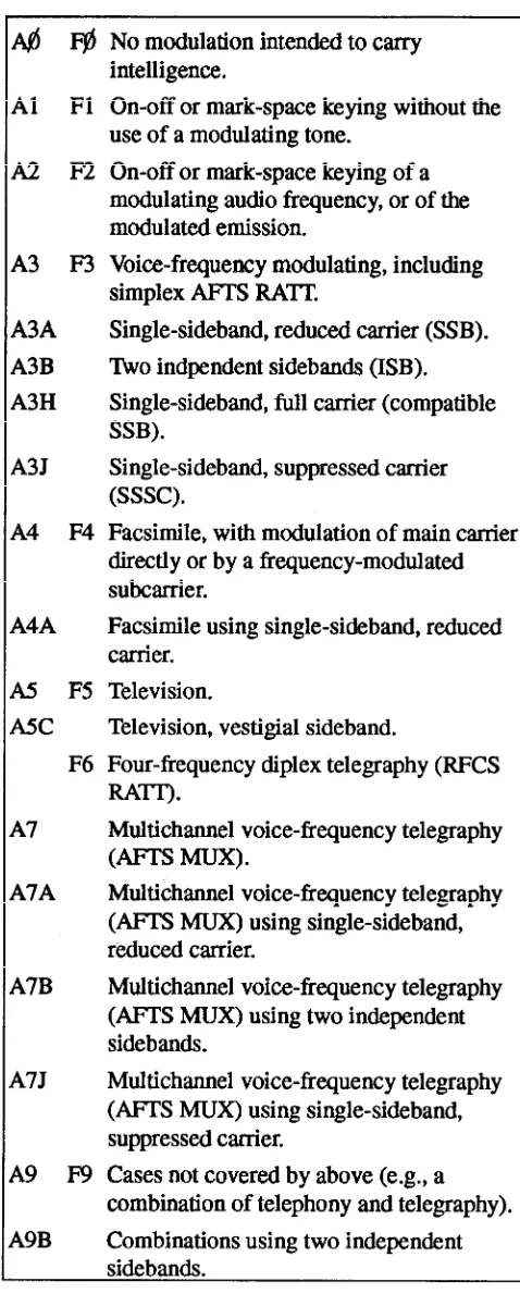
RADIO EMISSIONS
The emission class of an rf transmitter is deter-mined by the type of modulation used. The interna-tional designation system for AM and FM emissions is shown in table 1-2. It designates the rf emission by type, mode, and supplemental characteristics.
We will now discuss the basic equipment required for communications.
TRANSMITTERS
For rf communications to take place, a signal has to be generated. Generating the signal is the job of the transmitter. The following paragraphs will very briefly discuss basic transmitters and transmitter fundamen-tals.
TRANSMITTER FUNDAMENTALS
Equipment used for generating, amplifying, and transmitting an rf carrier is collectively called a radio transmitter. Transmitters may be simple, low-power units, for sending voice messages a short distance or highly sophisticated, using thousands of watts of power for sending many channels of data (voice, tele-type, telemetry, t.v., etc.,) over long distances.
[image:14.615.328.567.41.641.2]Basic transmitters are identified by their method of modulation: continuous wave (CW), amplitude modu-lation (AM), frequency modumodu-lation (FM), or single-sideband (ssb). We will first describe the types of modulation. We will then describe briefly the basic transmitters themselves.
Table 1-2.—Types of Radio Emissions
MODULATION
Modulation is the process of varying some charac-teristic of a periodic wave with an external signal. The voice frequencies (about 110-3,000 Hz) are contained
in the audio frequency spectrum, 10-20,000 Hz. In na-val communications the terms voice communications and audio communications are sometimes used inter-changeably. The audio signal is impressed upon the rf carrier because it is impractical to transmit frequen-cies in the audio range due to their excessive wave-length.
Three characteristics of the carrier wave may be varied, or modulated, at an external signal rate: ampli-tude, frequency, and phase. The following paragraphs discuss each type of modulation.
Amplitude Modulation (AM)
Amplitude modulations the process of combining audio frequency and radio frequency signals so that the
amplitude of the radio frequency waves varies at an
audio frequency rate.
Frequency Modulation (FM)
Frequency modulation is a process in which the
frequency of the carrier wave is made to vary. An FM
signal should remain constant in amplitude and change
Frequency-Shift Keying (FSK)
Frequency-shift keying is considered a form of FM. It is a digital mode of transmission commonly used in radioteletype applications. In FSK the carrier is present all the time. In a keyed condition, the carrier frequency changes by a predetermined amount called
the mark frequency. The unkeyed state is called a space.
Phase-Shift Keying (PSK)
Phase-shift keying is similar to FSK except that the phase, not the frequency, is shifted. The primary ad-vantage of PSK is that it can be accomplished in an am-plifier stage.
Pulse Modulation
Pulse modulation is accomplished by varying the characteristics of a series of pulses. This can be done by varying the amplitude, duration, frequency, or posi-tion of the pulses. It can also be done through coding. Pulse modulation is especially suited for use with com-munications systems incorporating time-division mu-tiplexing.
BASIC TRANSMITTERS
Remember, transmitters are generally divided ac-cording to their type of modulation. In the discussion below, we describe very briefly how each type oper-ates to help you differentiate between them.
CW Transmitter
A basic CW transmitter is shown in figure 1-3. CW is one of the oldest and least complicated forms of communications. Two advantages of CW are a narrow
bandwidth, which requires less power out, and clarity,
[image:15.617.150.440.473.676.2]even under high noise conditions. The major disadvan-only in frequency.
tage of a CW transmitter is that it must be turned on and off at specific intervals to produce Morse code keying (dots and dashes). This method is very slow by modern day standards. A better method of transmitting is AM.
AM Transmitter
Figure 1-4, a block diagram of an AM transmitter, shows you what a simple AM transmitter looks like. The microphone converts the audio frequency input to electrical energy. The driver and modulator amplify the audio signal to the level required to modulate the carrier fully. The signal is then applied to the power amplifier (pa). The pa combines the rf carrier and the modulating signal to produce the AM signal for trans-mission.
FM Transmitter
A block diagram of an FM transmitter is shown in figure 1-5. The transmitter oscillator is maintained at a constant frequency by a quartz crystal. This steady sig-nal is passed through an amplifier, which increases the amplitude of the rf subcarrier. The audio signal is ap-plied to this carrier phase-shift network. Here, the fre-quency of the carrier shifts according to audio signal variations. The FM output of the phase-shift network is
fed into a series of frequency multipliers that increase the signal to the desired frequency. The signal is then amplified in the power amplifier and coupled to the an-tenna.
Two important things to remember are (1) the amount of variation from the carrier frequency de-pends on the magnitude of the modulating signal and (2) the rate of variations in carrier frequency depends on the frequency of the modulating signal.
The FM transmitter is better than an AM transmit-ter for communications purposes because FM is less affected by static and other types of interference. An even better transmitter is the single-sideband transmit-ter, or ssb. Let’s look at some of the advantages of ssb transmitters.
SINGLE-SIDEBAND TRANSMITTER
In ssb communications, the carrier is suppressed (eliminated) and the sideband frequencies produced by the carrier are reduced to a minimum. This means no carrier is present in the transmitted signal. It is re-moved after the signal is modulated and reinserted at the receiver during demodulation. Since there is no carrier, all the energy is concentrated in the side-band(s).
Figure 1-4.—AM transmitter block diagram.
Figure 1-5.—FM transmitter block diagram.
We can make ssb even more efficient by removing one of the sidebands. By filtering out one of the side-bands before it reaches the power amplifier, all the transmitter energy is concentrated into one side-band instead of being split between the carrier and two sidebands. This allows us to use less power for transmission. Other advantages are a narrower re-ceiver bandpass and the ability to place more signals in a small portion of the frequency spectrum. Figure 1-6 is a block diagram of a ssb transmitter.
RECEIVERS
Earlier you were introduced to one link in a com-munications system, the transmitter. All that is needed to complete the system is a radio receiver. A receiver
processes modulated signals and delivers, as an output, a reproduction of the original intelligence. The signal can then be applied to a reproducing device, such as a loudspeaker or a teletypewriter.
RECEIVER FUNCTIONS
To be useful, a receiver must perform certain basic functions. These functions are reception, selection, de-tection, and reproduction.
Reception
Reception occurs when a transmitted electromag-netic wave passes through the receiver antenna and in-duces a voltage in the antenna.
Selection
Selection is the ability to distinguish a particular station’s frequency from all other station frequencies appearing at the antenna.
Detection
Detection is the extraction of the modulation from an rf signal. Circuits that perform this function are called detectors. Different forms of modulation require different detector circuits.
Reproduction
Reproduction is the action of converting the elec-trical signals to sound waves that can be interpreted by the ear.
RECEIVER CHARACTERISTICS
Understanding receiver characteristics is manda-tory in determining operational condition and for com-paring receivers. Important receiver characteristics are sensitivity, noise, selectivity, and fidelity.
Sensitivity
Sensitivity is a measure of receiver’s ability to re-produce very weak signals. The weaker the signal that can be applied and still produce a certain signal-to-noise (S/N) ratio, the better that receiver’s sensitivity rating. Usually, sensitivity is specified as the signal strength in microvolts necessary to cause a S/N ratio of 10 decibels, or 3.16:1.
Noise
All receivers generate noise. Noise is the limiting factor on the minimum usable signal that the receiver can process and still produce a usable output. Ex-pressed in decibels, it is an indication of the degree to which a circuit deviates from the ideal; a noise figure of 0 decibels is ideal.
Selectivity
Selectivity is the ability of a receiver to distinguish between a signal at the desired frequency and signals at adjacent frequencies. The better the receiver’s ability to exclude unwanted signals, the better its selectivity. The degree of selectivity is determined by the sharp-ness of resonance to which the frequency determining components (bandpass filters) have been engineered
Figure 1-7.—AM superheterodyne receiver and waveforms.
and tuned. Measurement of selectivity is usually done by taking a series of sensitivity readings in which the input signal is stepped along a band of frequencies above and below resonance of the receiver’s circuits. As the frequency to which the receiver is tuned is ap-proached, the input level required to maintain a given output will fall. As the tuned frequency is passed, the input level will rise. Input levels are then plotted against frequency. The steepness of the curve at the tuned frequency indicates the selectivity of the re-ceiver.
Fidelity
Fidelity is a receiver’s ability to reproduce the in-put signal accurately. Generally, the broader the bandpass, the greater the fidelity. Measurement is taken by modulating an input frequency with a series of audio frequencies and then plotting the output measurements at each step against the audio input. The curve will show the limits of reproduction.
Good selectivity requires a narrow bandpass. Good
fidelity requires a wider bandpass to amplify the
outer-most frequencies of the sidebands. Knowing this, you can see that most receivers are a compromise between good selectivity and high fidelity.
AM SUPERHETERODYNE RECEIVER
The superheterodyne receiver was developed to overcome the disadvantages of earlier receivers. A block diagram of a representative superheterodyne re-ceiver is shown in figure 1-7. Superheterodyne receiv-ers may have more than one frequency-converting stage and as many amplifiers as needed to attain the de-sired power output.
FM SUPERHETERODYNE RECEIVER
Fundamentally, FM and AM receivers function similarly. However, there are important differences in component construction and circuit design because of differences in the modulating techniques. Comparison of block diagrams (figures 1-7 and 1-8) shows that electrically there are two sections of the FM receiver that differ from the AM receiver: the discriminator (de-tector) and the accompanying limiter.
FM receivers have some advantages over AM re-ceivers. During normal reception, FM signals are static-free, while AM is subject to cracking noise and whistles. Also, FM provides a much more realistic reproduction of sound because of the increased number of sidebands.
SINGLE-SIDEBAND (SSB)
Figure 1-9 is a block diagram of a basic ssb re-ceiver. Though the ssb receiver is not significantly dif-ferent from a conventional AM superheterodyne receiver, it must use a special type of detector and a car-rier reinsertion oscillator. The oscillators in a ssb re-ceiver must be extremely stable. In some cases, a frequency stability of plus or minus 2 hertz is required. You can see that frequency stability is the most impor-tant factor of ssb equipment.
Ssb receivers may use additional circuits that en-hance frequency stability, improve image rejection, or provide automatic gain control (age). However, the circuits shown in figure 1-5 will be found in all single-sideband receivers.
AMPLIFICATION
Because the incoming signal may be weak and be-cause a certain minimum voltage level is required for the auxiliary equipment to operate, considerable am-plification must take place before the receiver output is used to drive speakers, headphones, or terminal equip-ment. This is usually called the gain of the receiver. Gain is a term used to describe an increase in current, voltage, or power. For example, if the detector, which removes the desired intelligence, requires 1 volt to op-erate and if the input to the receiver is 1 microvolt, a to-tal amplification of 1 million is required before detection. If the loudspeaker requires 10 volts, another voltage amplification of 10 is necessary between the detector and the loudspeaker.
The gain of an amplifier is expressed in decibels (dB). The decibel is a means of measuring relative lev-els of current, voltage, or power. Most often it is used to show the ratio between input power and output power. This ratio is expressed as gains and losses, where a mi-nus (–) sign placed before dB indicates a loss and a plus
(+)(or no sign at all) indicates a gain. The number of decibels change between two power values can be com-puted by the formula:
The comparison of dB’s to power ratio is shown in table 1-3. You can see instantly the reason behind us-ing the decibel system. It is much easier to say the sig-nal level has increased 40 dB than to say it has increased 10,000 times.
Examining table 1-3 again, you can see that an in-crease of 3 dB indicates a doubling of power. The re-verse is also true. If a signal decreases by 3 dB, half the power is lost. For example, a 100-watt signal
de-creased by 3 dB will equal 50 watts, while the same
100-watt signal increased by 3 dB will equal 200 watts. It’s important to understand that no matter how
much power is involved, a loss or gain of 3 dB always
represents a halving or doubling of the output power.
Technically, the dB level of a signal is a logarith-mic comparison between the input and output signals. Table 1-4 shows the common logarithms used to calcu-late dB. Normally the input signal is used as a refer-ence. However, sometimes a standard reference signal is used. The most widely used reference level is a 1 milliwatt signal. Decibels measured in reference to 1 milliwatt are abbreviated dBm. A signal level of 3 dBm is 3 dB above 1 milliwatt and a level of-3dBm is 3 dB below 1 milliwatt. The formula for dBm is a varia-tion of the dB power formula:
As a Navy technician, you will use the dBm system of measurement often to perform receiver sensitivity tests. For example, a receiver rated at -110 dBm will detect a signal 110 dB below 1 milliwatt. Suppose the
Figure 1-9.—Basic ssb receiver.
Table 1-3.—Decibel to Power Ratio
Table 1-4.—Logarithms
receiver’s sensitivity drops to -107 dBm. Since a loss of 3 dB reduces the sensitivity by 1/2, the input signal will have to be twice as large to be detected.
TRANSCEIVERS
A transceiver is a unit, usually enclosed in a single case, that combines a transmitter and receiver using a common frequency control. Transceivers are used ex-tensively in two-way radio communications at all fre-quencies, and in all modes.
The primary advantage of using a transceiver rather than a separate transmitter and receiver is cost. In a transceiver, many of the components can be shared during both transmit and receive operations. Another advantage is that transceivers can be tuned more easily than separate units.
problem with most transceivers, some do have provi-sions for separate transmit and receive operations, al-lowing them to overcome the problem.
ANCILLARY EQUIPMENT
Now that we have looked at the basic components of a communications system, let’s identify some of the ancillary equipment required to make a transmitter and receiver useful.
HANDSET
A handset converts acoustical (sound) energy into electrical energy, which is used to modulate a transmit-ter. It also converts electrical energy into acoustical en-ergy for the reproduction of the received signal.
To key a transmitter, the push-to-talk button is de-pressed, closing the dc keying circuit, which places the transmitter on the air. The handset is normally con-nected to a radio set control but can be used locally at the transmitter. Using the “local” option is a good way to determine whether a problem exists in the transmit-ter or remote equipment.
RADIO SET CONTROL
The radio set control provides the capability to control certain transmitter functions and the receiver output from a remote location. Some control units con-tain circuits for turning the transmitter on and off, voice modulating the transmission, keying when using CW, controlling receiver output, and muting the re-ceiver when transmitting.
A representative radio set control unit is shown in figure 1-10. As many as four of these units maybe par-alleled to a single transmitter/receiver group to provide additional operating positions. This setup is often found aboard ship when a transmitter or receiver is controlled from various locations like the bridge or combat information center.
TRANSMITTER TRANSFER SWITCHBOARD
The transmitter transfer switchboard allows the re-mote control station functions and signals to be trans-ferred selectively to the transmitters. Figure 1-11 shows a transfer switchboard that allows the functions and controls of anyone, or all, of 10 remote control sta-tion funcsta-tions and signals to be transferred selectively to any one of six transmitters. Each knob corresponds
Figure 1-10.—Radio set control
Figure 1-11.—Transmitter Transfer Switchboard (SB-988/SRT).
to a remote control station and has 8 operating posi-tions. Positions 1 through 6 correspond to attached transmitters. The seventh position (X) allows for switching of the transmitters to another switchboard. The eighth position (OFF) removes the remote from the system.
RECEIVER TRANSFER SWITCHBOARD
The receiver switchboard allows the audio outputs from the receivers to be transferred to remote control station audio circuits. A representative receiver trans-fer switchboard is shown in figure 1-12. This switch-board contains 10 seven-position switches. Each switch corresponds to a remote control station and each switch position (1 through 5) represents a re-ceiver. Position X allows the circuits attached to the switch to be transferred to another switchboard.
ANTENNAS
An antenna is a conductor or system of conductors that radiates or intercepts energy in the form of electro-magnetic waves. An antenna can be simply apiece of wire; but in practice, other considerations make the de-sign of an antenna system complex. The height above ground, conductivity of the earth, antenna shape and dimensions, nearby objects, and operating frequency are just a few of the factors affecting the radiation field pattern.
Information on antenna theory, basic antennas, and wave propagation will be available in Antennas &
Wave Propagation, volume 7, of this training series.
Currently, you can find information in Navy Electric-ity and Electronics Training Series (NEETS), Module 10, Introduction to Wave Propagation, Transmission
Lines, and Antennas, NAVEDTRA 172-10-00-83.
SYNCHROS AND SERVOS
In many electromechanical systems, the angular position of a shaft must be transmitted from one loca-tion to another without an actual mechanical linkage. You have seen examples of this in mast-mounted rotat-ing directional antennas and the automatic tunrotat-ing func-tion of receivers and transmitters from remote locations. A widely used method employs ac machines that operate as single-phase transformers. These ma-chines are called synchros.
Synchro receivers contain sets of gears that do the actual moving of the device to which the synchro is at-tached. These receivers are light-duty devices,
de-Figure 1-12.—Receiver Transfer Switchboard (SB-973/SRT).
signed to move small loads or to produce small amounts of torque. When the shaft to be driven at the remote location is connected to an indicating device or some light load, the synchro receiver is capable of de-veloping the necessary torque. But, if the load is a heavy load and more torque is required, torque (power) amplification is required. A control system capable of delivering larger amounts of power or torque is known as a servo mechanism, or servo.
You will encounter many systems that use sychros and servos. You can find detailed information about these devices in the Military Standards Handbook, MIL-HDBK-225 and NEETS, Module 15, Synchros,
CHAPTER 2
SYSTEMS EQUIPMENT
CONFIGURATIONS
INTRODUCTION
In chapter 1, we discussed basic system requirements. In this chapter, we will look at each equipment configuration. We will then link them together, forming a block diagram of the systems covered. We will discuss naval equipment from extremely-low-frequency through super-high-frequency. We also will look at microwave communications, the Single Audio System, teletype equipment, portable and pack radio equipment, and the Communications Link Interface Planning System.
At various points in the chapter, we review basic principles associated with the larger topic. The purpose of those reviews is to refresh your memory, in case you have not worked in the area for sometime.
After completing this chapter, you should be able to:
Identify system equipment configurations and how they link together
Recognize various extremely-low-frequency through super-high-frequency naval equipment
Compare a simplex relay system with a duplex relay system in microwave communications
Identify teletype equipment and portable and pack radio equipment
Identify the Communications Link Interface Planning System
SHIPBOARD COMMUNICATIONS OVERVIEW
Shipboard communications are now highly sophisticated. Nearly all the communications requirements for a ship can be met with fewer, more versatile, pieces of equipment. This versatility came about through improved equipment design and installation.
As communications equipment became more capable and complex, the need for an orderly process of identifying equipment by designation became apparent. The process that was developed identified equipment from the system level down to the part level. The highest level designator, system, describes
pieces of equipment that work together for a specific function. The lowest level designator, part, describes one piece, like a resistor. The following paragraphs describe the various levels in greater detail.
SYSTEM
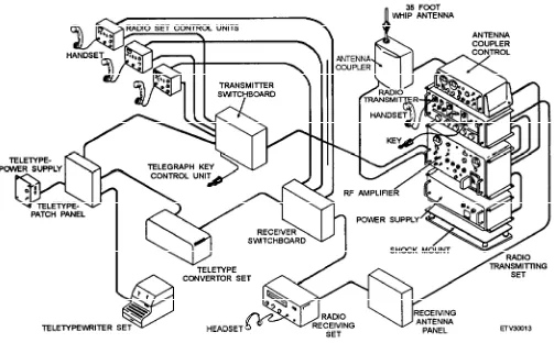
Figure 2-1 illustrates the equipment included in a typical system to meet these communication requirements.
SET
A SET consists of a unit or units and the assemblies, subassemblies, and parts connected to perform a specific function. Two examples are radio receiving sets and radio transmitting sets.
GROUP
A GROUP is a collection of units, assemblies, subassemblies, and parts that (1) is a subdivision of a set or system and (2) cannot perform a complete operational function. A good example is an antenna coupler group.
UNIT
A UNIT is a combination of parts, subassemblies, and assemblies mounted together that can normally
operate independently of other equipment. An example of a unit is the power supply.
ASSEMBLY/SUBASSEMBLY
An ASSEMBLY is a combination of two or more subassemblies joined to perform a specific function. A
SUBASSEMBLY consists of two or more parts that
form a portion of an assembly. It can be replaced as a whole, but some of its parts can be replaced individually.
[image:26.612.56.559.344.656.2]The distinction between an assembly and a subassembly is not always clear. An assembly maybe considered a subassembly when it is part of a larger or more complex assembly. A computer keyboard is a good example. By itself, it is an assembly. However, it is also a subassembly in a total computer system. Another example you are very familiar with is a circuit card.
Figure 2-1.—Communications system pictorial view.
PART size of elf transmitters and antennas makes transmission from submarines impractical.
A PART is one component or a combination of two or more components. A part cannot normally be disassembled without being destroyed. Resistors, capacitors, and transistors are examples of parts.
EQUIPMENT CONFIGURATIONS
The wide variety of communications equipment aboard ship can be overwhelming. This section separates that equipment into types of systems and identifies typical equipment associated with each type of system.
EXTREMELY-LOW-FREQUENCY/ VERY-LOW-FREQUENCY
COMMUNICATIONS
T h e e x t r e m e l y l o w f r e q u e n c y ( e l f ) c o m -munications system is used to send short “phonetic letter spelled out” (PLSO) messages from the Continental United States (CONUS) to submarines operating at normal mission speeds and depths. Elf can penetrate ocean depths to several hundred feet with little signal loss. This allows submarines to operate below the surface, improving their survivability by making detection more difficult.
The elf system is a one-way communications system from CONUS to at-sea submarines. The large
The principal use of the very-low-frequency (vlf) communications system is to provide fleet broadcasts to the submarine fleet and associated ships and activities thorughout the world. Additional uses are in long-range navigation and time and frequency broadcasts.
Vlf Transmit
Vlf transmission is normally considered a broadcast; that is, a one--way transmission, with no reply required. The extent and location of the area to be covered determine the transmitter location and power out.
For worldwide coverage, the Navy has installed seven transmitters whose power out ranges from 0.25 to 2.0 megawatts. These transmitters, such as the AN/FRT-87, can operate in either the interrupted continuous wave (icw) or frequency shift keying (fsk) mode. A typical vlf radio transmitting station is shown in figure 2-2.
Vlf Receive
The vlf receive system receives fsk and icw radio transmissions and then reproduces the intelligence that was broadcast. Receivers used for vlf communications are the AN/BRR-3, AN/FRR-21, AN/WRR-3, and
URR-R389. Figure 2-3 illustrates a typical vlf receiving system, using the AN/BRR-3 receiver. Most surface ships no longer receive vlf broadcasts. However, you will probably find one of these receivers mounted somewhere in your message center or radio room.
LOW-FREQUENCY COMMUNICATIONS
The low-frequency (lf) band occupies a very small portion of the radio frequency spectrum. However, the
Navy’s requirement to provide the best possible communications to the fleet requires operation on all frequency bands. The low-frequency band is used for long-range direction finding, encrypted medium- and long-range communications, and aeronautical radio navigation.
Lf Transmit
The low-frequency transmitter is a part of the Fleet Multichannel Broadcast System, operating at high
Figure 2-3.—Typical vlf receiving system.
power over long distances. It provides eight channels of frequency-division multiplex rtty traffic on each transmission. The AN/FRT-72 transmitter is designed specifically for this purpose. It produces 50-kW peak-envelope power (25-kW average power) and covers a frequency range of 30 to 150 kHz. Low-frequency transmitters are normally used only on shore stations.
Lf Receive
The low-frequency receive system receives lf broadcasts and reproduces the intelligence that was transmitted. A typical lf receive system is shown in figure 2-4. The antennas receive the lf signal and send it to the multicoupler and patch panel. The multicoupler and patch panel (AN/SRA-17 and AN/SRA-49) allow the operator to select different antennas and connect them to various receivers. In the system shown in figure 2-4, the receiver can be either the AN/SRR-19A or the R-2368A/URR. These receivers operate in the frequency ranges of 30 to 300 kHz and 14 kHz to 30 MHz, respectively.
The receiver audio is fed to the SB-973/SRR receiver transfer switchboard. As we explained earlier, this allows the received audio to be connected to numerous pieces of equipment. In figure 2-4, the audio is connected to either an AN/URA-17 or CV-2460 convertor comparator, which converts the received signal to dc for use by the teletype (tty) equipment. From the convertor, the dc signal is fed to a dc patch panel (SB-1203/UG). The signal can then be sent to any crypto equipment attached to the patch panel. The crypto equipment decrypts the signal and routes it to the red patch panel (SB-1210/UGQ). The signal can
then be patched to a teletype printer for plain text printing, or to a reperforator, where a paper tape will be punched and stored for later printing.
HIGH-FREQUENCY COMMUNICATIONS
The high-frequency (hf) band is shared by many domestic and foreign users. Portions scattered throughout the band are assigned to the military. The Navy’s communications requirements have grown rapidly, severely taxing its portion of the spectrum. Satellite communications has relieved some of this congestion and, for some types of service, has replaced hf for long-distance communications, pushing hf into a back-up role. However, even with the use of satellite communications, hf will continue to be in high demand for sometime. We will cover satellite communications in chapter 3.
Naval communications within the hf band are grouped into four general types: point-to-point, ship-to-shore, ground-to-air, and fleet broadcast. All but the fleet broadcast are normally operated two-way.
Point-to-Point
Point-to-point systems provide communications over long-distance trunks or via links between fixed terminals. A trunk is normally a message circuit b e t w e e n t w o p o i n t s u s i n g c a b l e , f i b e r , o r telephone circuits. A link is a transmitter/receiver system connecting two locations. The two locations normally use directional, high-gain antennas that increase the effective radiated power, reduce the chance of interference, and boost the sensitivity of the
receiving system. With the path length and direction fixed, propagation factors are simplified. This provides highly reliable hf communications.
powered transmitters, lower noise receivers, and more efficient antennas.
Fleet Broadcast Ship-to-Shore
High-frequency atmospheric communications between shore stations are relatively easy because shore stations have sufficient space for efficient omnidirectional antennas or arrays that provide hf coverage of large areas. Ship-to-shore hf communica-tions are more difficult because the ship is moving and constantly changing direction. This change of direction and severe space limitations aboard ships make the installation of large, efficient hf antennas impractical.
To overcome these problems, ship-to-shore systems have two major differences from point-to-point systems. First, shipboard antennas are omni-directional. Second, several frequencies are usually assigned for each circuit. If one frequency starts to drop out, another can be selected to match the propagation path conditions between the ship and the shore terminal.
Ground-to-Air
The use of hf radio for ground-to-air com-munications is similar to its use for ship-to-shore communications. An additional problem is that an aircraft moves much more rapidly than a ship. This rapid movement (plus additional space limitations) requires that all major circuit im-provements be made at the ground stations. Examples of improvements that can only be made to the ground station are higher
As the name implies, this service involves broadcast area coverage from shorebased transmitters to ships at sea. To overcome propagation problems, messages are sent on several frequencies at the same time (frequency-diversity). Space-diversity with physically separated receive antennas also helps overcome propagation problems.
Now let’s look at typical shipboard high-frequency transmit and receive systems.
Shipboard HF Transmit
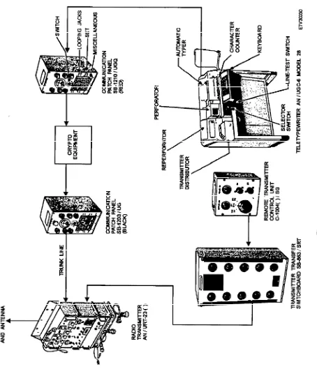
The high-frequency transmit signal can contain either voice or teletype information. Figure 2-5 shows a typical shipboard high-frequency transmit system.
The same equipment used to receive teletype messages on low frequencies (teletype, DC Patch Panel SB-1210/UGQ, crypto equipment, and DC Patch Panel SB-1203/UG) are used to send teletype messages on the high-frequency system; but of course, in reverse order.
An AN/UCC-1(V) or CV-2460 telegraph terminal converts a dc signal into a tone signal. This signal is fed to the SB-988/SRT transmitter transfer switchboard. A C1004 transmit keying and control/teletype is used to key the transmitter during tty operation. Voice communications also can be connected to the SB-988/ SRT switchboard. The voice communications are developed at a handset connected to the C-1138 radio
Figure 2-5.—Shipboard hf transmit system.
Figure 2-6.—Shipboard hf receive system.
set control. The output of the radio set control is then fed to the switchboard.
The transmitter transfer switchboard allows operators to select the proper transmitter for the selected frequency. The AN/URT-23 transmitter receives its input from the switchboard and changes the signal to a modulated rf signal that is fed to the AN/SRA-34, 56, 57, 58, or AN/URA-38 antenna coupler. The antenna coupler matches the output impedance of the transmitter to the input impedance of the antenna. Antenna couplers also allow more than one transmitter to be connected to the same antenna as long as certain conditions are met. When the signal reaches the antenna, it is radiated into the atmosphere.
Shipboard Hf Receive
A typical shipboard hf receive system is shown in figure 2-6. A transmitted signal similar to the one previously discussed is received by the antenna and converted from electromagnetic energy to electrical energy. The signal is fed to an antenna patch panel where it can be distributed to any number of receivers.
In figure 2-6, a receiver (R-1051/URR, R-2368/ URR, or R-1903/URR) converts the rf signal into either a teletype signal (fsk) or voice. The receiver output is then fed to the SB-973/SRR receiver transfer switchboard. The teletype signal from the switchboard follows the same path used by the low-frequency signal we discussed earlier. Identical pieces of equipment are used. The voice signal from the receiver switchboard is sent to the C-1138 radio set control and
Figure 2-7.—Vhf transmit and receive system.
fed to a handset. The voice signal also can be sent from the switchboard to an AM-3729 remote speaker amplifier and then to a speaker. This allows the user to listen to the signal without having to hold the handset.
VERY-HIGH-FREQUENCY COMMUNICATIONS
The Navy uses the very-high-frequency (vhf) band for mobile communications such as bridge-to-bridge, among boat crews, and for amphibious operations and landing parties.
Vhf Transmit
connected to radio set control, C-1138. The radio set control output is fed to transmitter transfer switchboard, SB-988/SRT. The switchboard performs the same function as it does in the lf and hf systems. The output of the switchboard is connected to the transmit side of the transmitter/receiver (transceiver), AN/VRC-46 or AN/VRC-80. The transceiver converts the input signal to an rf signal for transmission and the rf is radiated into the atmosphere by the antenna.
in sight of each other, though the distance traveled by the signal is much greater than for surface communications.
The uhf system uses a transceiver. However, we will still describe the transmit and receive functions separately. Although this description pertains to voice communications, uhf equipment can process tty data in the same way that the hf system does.
Vhf Receive
Uhf Transmit
Again, look at figure 2-7. The incoming signal is picked up by the antenna. This signal is fed to the receive side of the transceiver. The transceiver output is fed to the receiver transfer switchboard. The switchboard output is connected to either radio set control or to a speaker amplifier, AM-3729, or both, depending on the user’s preference. The output of the radio set control is fed to the handset and the speaker amplifier output is routed to the speaker.
ULTRAHIGH-FREQUENCY COMMUNICATIONS
The ultrahigh-frequency (uhf) band is used for line-of-sight (short range) command and control communications. As we stated earlier, line-of-sight means that both antennas are aimed at one another, with no obstruction in between.
This band is also used for satellite com-munications. Satellite communications are line-of-sight communications because the antennas remain
A basic block diagram of a uhf transmit system is shown in figure 2-8. On the transmit side of the
nonsecure voice system, the operator at a remote
location talks into the handset. The handset is connected to a C-1138 radio set control. The radio set control is connected to an SB-988/SRT transmitter transfer switchboard, which is connected to the transmitter.
On the transmit side of the secure voice system, the operator talks into the secure voice remote phone unit (RPU). The RPU is connected to the secure voice matrix, which is the tie point for the connection of multiple remote phone units. The matrix output is fed to the secure voice equipment that encrypts the information. This encrypted information is then fed to an SB-988/SRT transmitter transfer switchboard.
The transmitter switchboard performs the same function we described for previous systems. The switchboard output is connected to the transmit side of the AN/SRC-20/21 or AN/WSC-3, which is connected
Figure 2-8.—Uhf transmit.
to an AN/SRA-33 or OA-9123 antenna coupler. The coupler output is then fed to an antenna.
Uhf Receive
A basic block diagram of a uhf receive system is shown in figure 2-9. Most of the components are the same as those used in the transmit function. We will, therefore, identify by specific designator only the components that are unique to the receive function. The receive signal is picked up by the antenna and fed to the receive side of the transceiver through the antenna coupler. The receiver output is connected to an SB-973/SRR receiver transfer switchboard. It is then connected to either the nonsecure or secure voice system, depending upon the received transmission mode.
When a nonsecure signal is received, the output of the receive transfer switchboard is fed to either the radio set control or to the AM-3729 speaker amplifier, or both, depending on user preference.
If a secure voice transmission is received, the output of the switchboard is connected to the secure
voice equipment and decrypted. This output is fed to the secure voice matrix. The secure voice matrix output is fed to the RPU, where the signal is converted back to its original form.
SUPERHIGH-FREQUENCY COMMUNICATIONS
As we discussed in the previous chapter, two primary uses of the superhigh-frequency (shf) band are microwave and satellite communications. The AN/FSC-79 SHF terminal and satellite com-munications will be covered in the next chapter. In the following paragraphs, we will discuss line-of-sight and tropospheric scatter microwave communications.
MICROWAVE COMMUNICATION SYSTEMS
Microwave systems, such as the AN/FRC-84 and AN/FRC-170(V), are used to relay multiplex signals from point to point. A simplex relay system pro-vides one-way communications and consists of a transmitting terminal, a certain number of repeaters,
Figure 2-10.—Basic microwave relay system.
and a receiving terminal. Figure 2-10A shows you such a system. A duplex relay system (figure 2-10B) provides two-way communications by using two simplex systems, one transmitting in one direction and the other transmitting in the opposite direction. The duplex system is further refined by using a single antenna for transmitting and receiving. This is done by using different transmitting and receiving frequencies and by using a duplexer in the transmission line.
The rf equipment in terminal and repeater stations are basically the same. Terminal equipment can be converted to repeater equipment and vise versa. Let’s
take a look at a typical microwave transmitter and receiver.
MICROWAVE TRANSMITTER
A typical microwave transmitters shown in figure 2-11. In operation, the output of a telephone multiplex terminal, which consists of a frequency multiplexed AM carrier signal, is applied to the terminal transmitter. This input signal (baseband signal) also could be a television signal or any other form of signal to be transmitted. A pre-emphasis network accentuates the high frequencies, relative to the low, to improve the
Figure 2-11.—Typical microwave transmitter.
MICROWAVE RECEIVER
A typical microwave receiver is shown in figure 2-12. Though not shown, sensing and alarm functions are integral to all microwave communications equipment.
During system operation, the signal from the an-tenna passes through a waveguide preselector that eliminates interference from adjacent rf channels. The signal then enters a waveguide filter tuned to its fre-quency, which rejects all other unwanted frequencies. Next, the signal passes through an isolator that minim-izes intermodulation noise and holds the VSWR below 1.2:1. The signal is then mixed with the local oscillator (LO) output to produce the standard 70-MHz inter-mediate frequency (IF). The IF output is amplitude-limited and applied to an automatic frequency control (afc) discriminator, which controls the frequency of the LO. The signal is also applied to an IF discrimina-tor, a de-emphasis circuit, and a squelch circuit that disconnects the baseband amplifier and demultiplex-ing equipment if noise increases above a preset level. After the squelch circuit, the signal passes through a baseband amplifier and then to the demultiplexing equipment, where the original intelligence is retrieved.
Microwave communications systems operating in the shf portion of the frequency spectrum use the
principle that propagation approaches an optical straight-line path. Propagation takes place in the lower atmosphere and is affected by meteorological factors. Communications in this medium are usually either line-of-sight or tropospheric scatter.
LINE-OF-SIGHT (LOS)
A line-of sight microwave system consists of one or more point-to-point hops. Each hop is designed to be integrated into a worldwide communications network. Los system characteristics are as follows:
Propagation—Free space as affected by the tro-posphere.
Communications Capacity/Bandwidth—Up to 600-4kHz voice channels; wideband, can accept TV.
Range—Usually 50 to 150 km (31 to 95 statute miles). This depends upon antenna height, earth curva-ture, and intervening terrain.
RF Power—Usually less than 10 watts.
[image:36.620.77.570.401.679.2]Antennas—Both transmitting and receiving antennas are horn-driven paraboloids, providing high gain and narrow beam widths. In some applications, plane reflectors are used with the paraboloids.
Figure 2-12.—Typical microwave receiver.
Reliability—Designed to be operational more than 99% of the time, including the periods of poor propagation.
Countermeasures—Because of antenna directiv-ity, the system is difficult to jam. Additionally, the sys-tem should not be susceptible to nuclear disturbances of the ionosphere.
Application—Because of the bandwidth capa-bility and minimum site requirements, los is well adapted to moderate distance point-to-point multichan-nel communications (with repeaters), transmission of closed circuit TV, transmission of radar information from outlying sites, communications relay between locations in congested areas, and “antenna farms.”
TROPOSPHERIC SCATTER SYSTEM
At microwave frequencies, the atmosphere has a scattering effect on electromagnetic fields that allows for over-the-horizon communications. This type of communications is called tropospheric scatter, or
troposcatter for short. Troposcatter takes place mostly
at low altitudes, but some effect takes place at altitudes of up to 10 miles. Under the right conditions, troposcatter can take place over hundreds of miles.
A tropospheric scatter microwave system consists of one or more point-to-point hops (or sections). Each hop is designed so it can be integrated into the worldwide communications network of the Defense Communications System (DCS). Troposcatter links have the following characteristics:
Propagation—Free space as affected by the tro-posphere.
Communications capacity/bandwidth—Up to 600 4-kHz voice channels; wideband, can accept TV.
Range—Up to 800 km (500 statute miles).
RF Power—High; up to 75 kilowatts depending upon bandwidth, quality, and range.
Coverage—Point-to-point only.
Antennas—Both transmitting and receiving antennas are horn-driven paraboloids providing high gain and narrow beam widths.
Reliability—Designed to be operational more than 99% of the time, including periods of poor propa-gation.
Countermeasures—Extremely difficult to jam. Should not be susceptible to nuclear disturbances of the ionosphere.
Application—Meets the communications re-quirements between HF sites within its minimum skywave one-hop distance of about 400 miles and line-of-site of about 30 miles. It is especially useful where conditions prevent the use of line-of-sight communica-tions or if adverse propagation condicommunica-tions interfere with other transmission methods.
MULTIPLEXING
As we mentioned earlier, the rf spectrum has become very congested. The maximum number of transmissions taking place in the rf spectrum is being i n c r e a s e d t h r o u g h t h e u s e o f m u l t i p l e x i n g . Multiplexing refers to the simultaneous transmission of two or more messages over the same medium or channel at the same time. Multiplexing may be achieved in various ways, but the most common meth-ods are time-division multiplexing (tdm) and fre-quency-division multiplexing (fdm). Although several types of multiplexing equipment are available in the fleet today, the AN/UCC-1D is the most common.
TIME-DIVISION MULTIPLEXING
Time-Division Multiplexing (Tdm) is a method of combining analog signals for serial transfer. The signals are sampled at intervals and interwoven for transmis-sion. The speed of this multiplexed signal is faster than the original individual channel speed by a multiple equal to the number of combined signals. For example, if 5 signals are multiplexed, the data speed of each sig-nal must be multiplied by 5 to keep the sigsig-nals in syn-chronization. Tdm also results in an increase in the signal bandwidth because of the increased data speed.
Time-division multiplexing also can be used with digital signals, but this method is usually called
synchronous multiplexing.
FREQUENCY-DIVISION MULTIPLEXING
SINGLE AUDIO SYSTEM (SAS)
The Single Audio System (SAS) was developed to fulfill the requirement for an integrated secure/non-secure shipboard voice communications system. It consists of telephone sets, voice-signal switching de-vices, various control dede-vices, and field changes to existing equipment, in conjunction with other ele-ments of the overall shipboard radio communications system. The SAS is essentially the baseband (AM and/or FM ) hf, vhf, or uhf audio subset of the ship-board exterior communications system. It incorporates voice communications circuits, user control over the operating mode (both secure and nonsecure), and various degrees of operator control over voice circuit selection. Figure 2-13 shows the major equipment groups, subsystems, and their interrelationship.
There are two versions of SAS: an automated system (ASAS) and a manual system (MSAS). The voice switching equipment and means provided for user control over circuit selection are the two primary differences. Information in this section applies to both ASAS and MSAS, unless otherwise specified.
There is no specific list of equipment that makeup every SAS installation. There can be different types and quantities of equipment in each of the groups identified in figure 2-13. Equipment types and quantities are dictated by the communications requirements of individual ships and ship classes. The publication, Operation and Maintenance Instructions,
Single Audio System, NAVELEX
EE109-CA-OMI-010/El10 SAS, identifies, in tables 1-1 and 1-2, the SAS equipment commonly used in the fleet.
SYSTEM CAPABILITIES
The SAS incorporates basic capabilities for setting up and operating voice communications circuits. An SAS installation provides the unique capability to communicate in a secure or nonsecure mode, at the discretion of the operator, from a single telephone or NTDS device. This single audio interface with various crypto or plain subsystems is the essence of the SAS. The SAS provides the following options:
The user can select the transmit operating mode except for FLTSATCOM secure voice and PLAIN configurations.
The system can notify the user of the transmit operating mode selected, both visually and with audio indications.
The system can notify the user by visual indica-tion if the voice staindica-tion equipment is not con-nected to a crypto or plain subsystem.
The system can notify the user of any incoming secure (CIPHER) signals by both visual and audio indications except for the FLTSATCOM secure voice configuration.
The user can select a voice channel and have it indicated visually.
In addition to these capabilities, the ASAS version has the following features:
[image:38.619.87.556.444.703.2]A processor controlled, programmable voice
Figure 2-13.—Single Audio System (SAS).