Original Article
A novel set of individualized attachments for impacted
tooth traction based on 3D simulation and printing
technology: design and fabrication
Lei Han1, Tiancong Wang1, Le Hu2, Zhitong Lin3, Huang Li1, Jun Ji1
Departments of 1Orthodontics, 2Endodontics, 3Dentomaxillofacial Radiology, Nanjing Stomatological Hospital, Medical School of Nanjing University, Nanjing 210008, P.R. China
Received May 18, 2017; Accepted February 4, 2018; Epub March 15, 2018; Published March 30, 2018
Abstract:Objectives: To introduce new personalized attachment sets used for impacted tooth traction designed and fabricated by 3D simulation and printing technology. Methods: A set of customized attachments was designed, fab-ricated and applied for impacted tooth traction. Digital data of impacted tooth obtained from Cone Beam Computed Tomography (CBCT) was input into Computer-Aided Design (CAD) program to design the individualized attachment
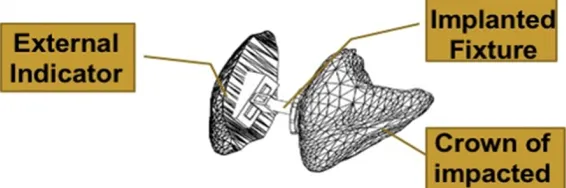
(including an implanted fixture and an external indicator). The implanted fixture, composed of an individualized
base, a guiding rod, a horizontal traction tube, and a vertical traction tube, was bonded to a surgically exposed crown surface. The external indicator was clipped on the vertical traction tube, which contained a resin embedded tooth labial surface and a vertical slot. 3 cases with bilateral labially impacted canines were enrolled in this study.
Results: The individual base was fit for the specific exposed area of the impacted tooth. The horizontal and vertical
traction tubes could be used to control embedded tooth movement in three dimensional direction. The embedded tooth movement was possibly accelerated because the whole tooth moved in the cancellous bone without cortex bone resistance. The detachable external indicator could monitor the real-time tooth position along with traction, which avoided repeated X-ray examination.The average traction time was 5 months. All impacted canines were upright in the arch and tight occlusal relationships were obtained after treatment. Conclusion: The individualized at-tachment sets for impacted toothtraction based on 3D simulation and printing technology proved to have a certain clinical application prospect.
Keywords: Impacted tooth, CBCT, CAD, 3D printing, individual attachment
Introduction
The management of an impacted tooth usually requires a cooperation between orthodonti- sts and maxillofacial surgeons. After surgically exposing the tooth crown and bonding attach-ment, the impacted tooth can be towed by orthodontic forces. Up to date, the attachments for impacted tooth traction were generally fin-ished products such as buttons, brackets or other devices [1-3]. Because the shape of the attachment base was not individually made, the base was not precisely fit for the surgically exposed tooth surface, which may greatly increase the attachment bonding failure risk [4]. Additionally, in treatment process, it is dif-ficult to accurately manage the acting point and direction of traction force. Thus, making the th-
ree dimensional control of the impacted tooth position and effective tooth movement is a challenging task [4-7].
resorption, designing of traction mechanics for embedded tooth, evaluation of orthodontic treatment difficulty and selection of suitable treatment method [11-13]. On the other hand, with the development of digital data, image acquisition obtained from CBCT, post-process-ing includpost-process-ing digital simulation, 3D image reconstruction and 3D printing, an individual-ized appliance to be used in the human body is possible. 3D printing, also referred as rapid prototyping, is a methodology using 3D com-puter models to reconstruct the physical model by addition of material layers. It combined Computer Aided Design and Manufacture (CAD and CAM) technology, laser manufacture tech-nology, and newly developed materials science, which is especially fit for making complicated devices and take less time to make. During recent years, it has been widely used in ortho-pedics, oral maxillary surgery, implantology, neurosurgery, plastic surgery and so on [14-20]. However, the individual attachment sets for impacted teeth made by 3D printing was seldom reported [4]. Therefore, based on the 3D simulation and 3D printing technology, we designed and fabricated a new individual attachment sets for the traction of impacted teeth according to the surgically exposed teeth surface, impacted teeth location and the
CBCT scanning and 3D reconstruction
All patients received CBCT scanning (NewTom VG, Italy). Shooting conditions (Scanning par- ameters/patient position): all patients were standing with their FH plane parallel to the ground, teeth biting in the intercuspal position and head fixed with the chin cap and head hold-er. The vertical cross cursor scanning baseline was adjusted to coincide with the sagittal mid-line, the horizontal cross cursor scanning base-line was adjusted to coincide with the FH plane. The scanning range was from the root of the nasion to the menton. Radiation dose was automatically adjusted according to the scan-ning range. The Cone Beam rotating anode was 110 KV and scanning thickness was 0.3 mm. Acquired data was saved in the common DICOM format (Digital Imaging and Communications in Medicine). The 3D digital image of teeth and jaws were constructed with the assistance of Mimics 17.0 software (Materialise, Belgium) after the process of data binarization, contour
[image:2.612.89.376.73.200.2]extraction, vectorization and 3D image recons-truction [20, 21]. Using the three dimensional image, the treatment diagnosis and plan for impacted teeth was made with the orthodontist and surgeon (Figure 1).
Figure 1. 3D digital image of jaws (A) and impacted teeth (B) by 3D recon-struction.
Figure 2. The CAD model of whole attachment sets.
designed movement path, in order to provide a new ap- proach of treating embedded teeth.
Materials and methods
Subjects
[image:2.612.92.375.254.348.2]The CAD of individual attachment sets model
On the basis of the 3D digital model construct-ed by mimics software, we importconstruct-ed the data into AutoCAD Mechanical software (Autodesk, American). According to the following parame-ters, we designed the individual attachment sets model (Figure 2) which was composed of two parts: an implanted fixture (Figure 3) and an external indicator (Figure 4). The implanted fixture was bonded on a surgically exposed crown surface, which was composed of an indi-vidualized base (Figure 3A), a guiding rod (Figure 3B), a horizontal traction tube (Figure 3C) and a vertical traction tube (Figure 3D). The CAD model of individual attachment sets were
The design of horizontal traction tube: The hori-zontal traction tube was positioned above the guiding rod. Its long axis direction was vertical to the long axis of the impacted teeth. The inner duct diameter was 0.56 mm × 0.70 mm (0.22 inch × 0.28 inch), which similar to the pre-scribed pre-adjusted orthodontic brackets (Figure 3C).
The design of vertical traction tube: The verti- cal traction tube was above the horizontal tr- action tube. Its long axis direction was par- allel to the the long axis of the impacted te- eth. The inner duct diameter was also 0.56 mm × 0.70 mm (0.22 inch × 0.28 inch) (Figure 3D).
Figure 3. The CAD model of the individual at-tachment base, guiding rod, horizontal trac-tion tube and vertical tractrac-tion tube.
Figure 4. The CAD model of external indicator.
Figure 5. The lateral view (A) and frontal view (B) of the individual resin at-tachment model.
exported using mimics soft-ware into STL format for 3D printing.
The design of implanted fixture
The design of individual at- tachment base: After consult-ing with the orthodontist and surgeon, the surgical expo-sure zone was determined. The personalized attachment base was designed to match and bond on the expos- ed embedded tooth surface (Figure 3A). The size (diame-ter at 2.5 mm) and thickness of the individual attachment base was similar to the tradi-tional finished button.
The design of the external indicator: The ex- ternal indicator contained a resin embedded tooth labial surface and a vertical slot. The resin embedded tooth labial surface was gen-erated with the exact the same shape of the impacted tooth labial surface. On the back of the indicator, a vertical slot was parallel to the long axis of the resin embedded tooth lab- ial surface. The size and direction of the verti- cal slot can be matched with the vertical trac-tion tube of the implanted fixture (Figure 4). It could be clipped on the vertical traction tube of the implanted fixture.
The manufacturing of the individual resin model and the casting of metal model
The STL format was imported into the rapid producing machine, Dental Wings (Canada) by which the individual resin attachment model was made (Figure 5A). After a series of embed-ding, casting precision technology and other processes, the metal attachment including the individual base, guiding rod, horizontal traction tube, vertical traction tube and the external indicator were casted for clinical use (Figure 6). Treatment phase: One of our clinical cases were presented (Figure 7). Phase 1: Eruption space expansion and anchorage design. After bonding the fixed orthodontic brackets, the orthodontic archwires were placed in sequence and the anchorage devices for impacted teeth
bone. The horizontal and vertical tube were exposed on the surface of the gum. According to the location of the impacted tooth, different traction mechanics were designed respec- tively. By the force 50 g applied by ligature wire or elastic chain between the horizontal trac- tion tube and the orthodontic archwire, the impacted teeth could vertically erupt. A sec- tional rectangular stainless steel cantilever, 0.017 × 0.025 inch was inserted into edgewise vertical traction tube, and connected to the anchorage device in horizontal direction, along which the impacted teeth moved in horizon- tal, buccal or labial direction (Figure 7B, 7C). The patients were scheduled for follow- up appointments four weeks later to control the movement of the impacted teeth. In every visit, the vertical traction guiding slot on the back of external indicator could be slipped into the vertical traction tube in order to reflect the real-time position of the impacted teeth in alve-olar bone. Phase 3: Precise adjustment for canines positions. For impacted canines, a suc-cessive finishing phase with a fixed appliance was applied to align the roots and close the remaining space (Figure 7D).
Clinical examination
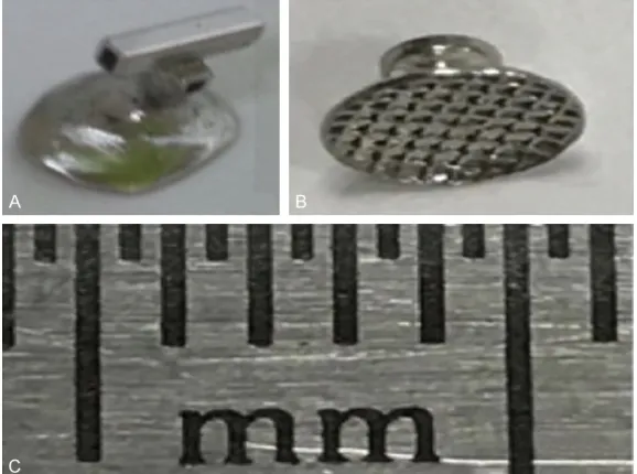
[image:4.612.89.378.72.287.2]For each patient, mobility of the impacted tooth was assessed after treatment. The criteria of tooth mobility was determined using Miller’s mobility index. The 3D position of the impacted Figure 6. The casted individulal (A) and traditional (B) metal attachment sets
for embedded tooth traction and the scale display of this ruler (1 millimeter of each scale) (C).
traction were secured by the three teeth adjacent to the impacted molar with a 0.019 × 0.025 inch stainless steel wire, the space for the impact-ed tooth eruption would be expanded if necessary (Figure 7B). Phase 2: Attachments bonding and eruption path-way control. Surgical proce-dures were then performed to expose the crown surface of the impacted teeth, on which the individual base was bo- nded (TransbondTM PLUS Co-
canines were displayed by the external indica-tor during the traction process.
Results
The base of the individual casting attachment was completely fit for the surgically exposed
[image:5.612.90.376.67.579.2]at any time during the traction process and determine its relationship with the su- rrounding teeth. Therefore, it reduced the frequency of X-ray examination which was previously necessary to locate the impacted teeth and adjust the traction force direc- tion.
Figure 7. Treatment for bilateral labially impacted upper canines. A: Before treatment; B, C: During treatment, Eruption space expansion, anchorage design, attachments bonding and eruption pathway control; D: After treat-ment, the impacted canines had good position and obtained tight occlusion relationship.
tooth surface which ensured strong adhesion. Additionally, it was convenient to bond the attachment after surgi-cally exposing the tooth sur-face. Attachment bonding fail-ure during the bonding and traction process may be av- oided.
Combined application of the horizontal and vertical trac-tion tube with the edgewise stainless steel archwire cou- ld achieve the complicated 3D teeth movement in differ-ent cases. The impacted te- eth could vertically erupt with the help of the force applied by ligature wire or elastic chain between the horizontal traction tube and the orthodontic archwire. Wi- th the interaction of the in- ner wall of the horizontal tr- action tube and the rectan- gular stainless steel arch-wire, the torque and couple required to control tooth mo- vement in the buccal-lingually place was achieved. Addi- tionally, a rectangular stain-less steel archwire was ins- erted into an edgewise verti-cal traction tube, and con-nected to the anchorage de0 vice in vertical direction, al- ong which the impacted tee- th moved horizontally. The tip and rotation of impact- ed tooth could also be adju- sted after the rectangular stainless steel archwire was inserted into the vertical trac-tion tube.
Three cases with bilateral labially impacted upper canines, including 2 females (11.2 years and 11.8 years old, respectively) and 1 male (12.1 years old), were selected. Orthodontically-assisted treatment, with surgical uncovering, was performed for all labially impacted canines. The mean traction period was 5 months. All impacted canines were upright in the arch and tight occlusion relationships were obtained after treatment. The impacted canines in three cases showed no distinguishable luxation.
Discussion
Impacted teeth are those with a significantly delayed eruption time. Permanent maxillary canines are the second most frequently imp- acted teeth after the third molar, at 2% preva-lence rate, twice as common in females. The incidence of canine impaction in the maxilla is more than twice that in the mandible [8, 22, 23]. Before 1970s, the treatment the impacted teeth was mainly determined by the surgeon and most were extracted during surgery [6]. With the development of orthodontic diagnosis and the technique of treating impacted teeth aided by CBCT, orthodontists are now playing an important role in the successful treatment of impacted teeth. Up to date, the location of impacted teeth, evaluation of treatment diffi-culty and selection of suitable treatment meth-od have become a necessary part in diagnosis and treatment planning [8, 13, 22, 24].
Nowadays the most common method for treat-ing embedded canines was surgically expostreat-ing the teeth, placing a bonded attachment and applying orthodontic forces to move the impact-ed tooth. There were two ways of attachment bonding: one step bonding technique and two steps bonding technique [25]. In those two methods, the traditional attachments such as prefabricated brackets or button were used for treating the embedded tooth. However, those traditional attachments had the following dis-advantages: Firstly, to facilitate the attachment bonding, surgeons sometimes had to remove excessive bone to expose the flat surface of the impacted teeth [5]. Because the base of the finished attachments was not closely fit for the surgically exposed embedded tooth sur-face and it was easy to come off from the tooth surface due to low shear strength resistance. The treatment was painful if the surgical expo-sure had to be done multiple times [26].
Secondly, Orthodontists could only bond the attachment and design the traction direction after the surgery. The ligature wire or elastic chain was placed between the attachment and the anchorage device for traction. The unfavor-able traction direction maycause attached gin-gival recession or alveolar margin loss and increased treatment time [5, 27-29]. Thirdly, the impacted teeth was invisible during the traction process before the impacted tooth was pulled out of the alveolar bone, there existed the risk of resorption of adjacent tooth or other tissues due to the compression of impacted teeth. The risk of resorption of adjacent tooth or other tissues due to the compression of impacted teeth also existed. Thus, making the monitor and control of the impacted teeth movement an uncontrollable process [8, 24]. To avoid this risk, repeated x-ray examination and attachment rebonding for adjustment were needed in clinical visits, which was harmful for the health of the patients.
To overcome the above shortcoming, we de- signed and fabricated an individualized atta- chment sets for impacted tooth traction based on 3D simulation and printing technology. Firstly, the surgically exposed embedded to- oth crown zone and traction direction was ini-tially determined after consultation discussion between orthodontist and surgeon aided by CBCT. We constructed the digital tooth crown surface on which we would bond the attach-ment on the basis of the 3D digital impacted tooth model constructed by mimics software, then we designed the individual attachment sets by AutoCAD software. The individual cast-ing attachment base by 3D printcast-ing could be precisely fit for the tooth surface by surgical exposure.
consisting of a loose network of trabecular bone. which was rich in blood vessels and ben-eficial to the alveolar bone remodeling after the teeth moved [30]. According to the Bio-Progressive Therapy theory proposed by Ri- ckets and other scholars in the early 80s, mov-ing the root of teeth in the cancellous bone and away from the cortical bones with light forces could promote effective physiological orth-odontic tooth movement [31, 32]. Thus, It was more favorable to move the impacted tooth horizontally or vertically and adjust the tip, rota-tion and rotarota-tion of the impacted tooth in can-cellous bone before it was pulled out of the alveolar bone. A rectangular stainless steel archwire was inserted into an edgewise vertical traction tube, and connected to the anchorage device, along which the impacted teeth moved in the horizontal direction. The impacted teeth could also erupt vertically with the help of forces applied by ligature wire or elastic chain between the horizontal traction tube and the orthodontic archwire. With the interaction of the inner wall of the horizontal duct and the rectangular stainless steel arch-wire, the torque and couple required the buccal-lingual root movement control could also be expressed. The tip and rotation of the impacted tooth could also be adjusted after the rectangular stainless steel archwire was inserted into the vertical traction tube.
Thirdly, we designed the external indicator which includes the resin embedded tooth labial surface and a vertical slot. On the back of the external indicator, the vertical slot could be clipped on the vertical traction tube. The spatial location and position of the impacted teeth could be displayed by a resin embedded tooth labial surface. Thus, the movement path of the impacted tooth could be precisely predicted during the movement process. There was no need for repeated X-ray examination to locate the embedded teeth and its relationship with the surrounding tissues.
However, this individualized attachment set was mainly used in the treatment of labially embedded tooth. It had limitation in treating the palatally impacted tooth. The guiding rod became too long to operate and the traction force couldn’t be applied conveniently when the horizontal traction tube and vertical traction tube were made to come out of labial mucosa. It was also uncomfortable for patient to
toler-ate the bulky attachments on the palatal sur-face of the mucosa.
Overall, The CBCT scanning, digital image pro-cessing, 3D simulation, and the 3D printing are successfully integrated and applied to the design and fabrication of the individual trac- tion attachment sets. In the future, with the development of 3D simulation and printing, the precision of metal attachment will be improved and the individual attachment will be more and more widely used in treating impacted teeth.
Acknowledgements
This work was supported by Medical Science and Technology Development Foundation, Nanjing Department of Health (grant number: YKK16163, YKK16160), Nature Science Foun- dation of Jiangsu Province (grant number: BK20171123) and Jiangsu Provinvial Medical Youth Talent (QNRC2016116), National Natural Science Fund Project (81470712, 81670960).
Disclosure of conflict of interest
None.
Address correspondence to: Jun Ji and Huang Li, Department of Orthodontics, Nanjing Stomatolo- gical Hospital, Medical School of Nanjing Universi- ty, Zhongyang Road 30, Xuanwu District, Nanj- ing 210008, P.R. China. Tel: 86-025-83620283; E-mail: [email protected] (JJ); Tel: 86-025-8362- 0282; E-mail: [email protected] (LH)
References
[1] Boyd RL. Clinical assessment of injuries in orthodontic movement of impacted teeth. I. methods of attachment. Am J Orthod 1982; 82: 478-486.
[2] Sherwood K. Evidence-based surgical-orth-odontic management of impacted teeth. Atlas Oral Maxillofac Surg Clin North Am 2013; 21: 199-210.
[3] Kaczor-Urbanowicz K, Zadurska M and Czo-chrowska E. Impacted teeth: an interdisciplin-ary perspective. Adv Clin Exp Med 2016; 25: 575-585.
[4] Faber J, Berto PM and Quaresma M. Rapid pro-totyping as a tool for diagnosis and treatment planning for maxillary canine impaction. Am J Orthod Dentofacial Orthop 2006; 129: 583-589.
[5] Kohavi D, Becker A and Zilberman Y. Surgical
tooth position as factors in periodontal break-down of treated palatally impacted canines. Am J Orthod 1984; 85: 72-77.
[6] Bishara SE. Impacted maxillary canines: a re-view. Am J Orthod Dentofacial Orthop 1992; 101: 159-171.
[7] Pignoly M, Monnet-Corti V and Le Gall M. Rea-son for failure in the treatment of impacted and retained teeth. Orthod Fr 2016; 87: 23-38. [8] Alqerban A, Jacobs R, Souza PC and Willems G.
In-vitro comparison of 2 cone-beam computed tomography systems and panoramic imaging for detecting simulated canine impaction-in-duced external root resorption in maxillary lat-eral incisors. Am J Orthod Dentofacial Orthop 2009; 136: 764-765.
[9] Baumgaertel S, Palomo JM, Palomo L and Hans MG. Reliability and accuracy of cone-beam computed tomography dental measure-ments. Am J Orthod Dentofacial Orthop 2009; 136: 19-25.
[10] Kiljunen T, Kaasalainen T, Suomalainen A and Kortesniemi M. Dental cone beam CT: a re-view. Phys Med 2015; 31: 844-860.
[11] Scarfe WC, Farman AG and Sukovic P. Clinical applications of cone-beam computed tomogra-phy in dental practice. J Can Dent Assoc 2006; 72: 75-80.
[12] Alqerban A, Jacobs R, Fieuws S and Willems G. Comparison of two cone beam computed to-mographic systems versus panoramic imaging for localization of impacted maxillary canines and detection of root resorption. Eur J Orthod 2011; 33: 93-102.
[13] Maverna R and Gracco A. Different diagnostic tools for the localization of impacted maxillary canines: clinical considerations. Prog Orthod 2007; 8: 28-44.
[14] Sarment DP, Sukovic P and Clinthorne N. Ac-curacy of implant placement with a stereolitho-graphic surgical guide. Int J Oral Maxillofac Implants 2003; 18: 571-577.
[15] Yanping L, Shilei Z, Xiaojun C and Chengtao W. A novel method in the design and fabrication of dental splints based on 3D simulation and rapid prototyping technology. J Adv Manuf Technol 2006; 28: 919-922.
[16] Peltola SM, Melchels FP, Grijpma DW and Kel-lomäki M. A review of rapid prototyping tech-niques for tissue engineering purposes. Ann Med 2008; 40: 268-280.
[17] Rengier F, Mehndiratta A, von Tengg-Kobligk H, Zechmann CM, Unterhinninghofen R, Kauczor HU and Giesel FL. 3D printing based on imag-ing data: review of medical applications. Int J Comput Assist Radiol Surg 2010; 5: 335-341. [18] Biglino G, Schievano S and Taylor A. The use of
rapid prototyping in clinical applications. In Tech 2011.
[19] Khalil W, EzEldeen M, Van De Casteele E, Sha-heen E, Sun Y, Shahbazian M, Olszewski R, Politis C and Jacobs R. Validation of cone beam computed tomography-based tooth printing using different three-dimensional printing technologies. Oral Surg Oral Med Oral Pathol Oral Radiol 2016; 121: 307-315.
[20] McGurk M, Amis AA, Potamianos P and Goodger NM. Rapid prototyping techniques for anatomical modelling in medicine. Ann R Coll Surg Engl 1997; 79: 169-174.
[21] Hahn HK, Millar WS, Klinghammer O, Durkin MS, Tulipano PK and Peitgen HO. A reliable
and efficient method for cerebral ventricular
volumetry in pediatric neuroimaging. Methods Inf Med 2004; 43: 376-382.
[22] Bedoya MM and Park JH. A review of the diag-nosis and management of impacted maxillary canines. J Am Dent Assoc 2009; 140: 1485-1493.
[23] Zhigui M, Chi Y, Shanyong Z, Qianyang X, Yuq-ing S and Pei S. Orthodontic extrusion of hori-zontally impacted mandibular molars. Int J Clin Exp Med 2014; 7: 3320-3326.
[24] Jacobs SG. Localization of the unerupted max-illary canine: how to and when to. Am J Orthod Dentofacial Orthop 1999; 115: 314-322. [25] Boyd RL. Clinical assessment of injuries in
orthodontic movement of impacted teeth. II. Surgical recommendations. Am J Orthod 1984; 86: 407-418.
[26] Jarjoura K, Crespo P and Fine JB. Maxillary ca-nine impactions: orthodontic and surgical management. Compend Contin Educ Dent 2002; 23: 23-6, 28, 30-1 passim; quiz 40. [27] Vanarsdall RL and Corn H. Soft-tissue
manage-ment of labially positioned unerupted teeth. July 1977. Am J Orthod Dentofacial Orthop 2004; 125: 284-93.
[28] Crean SJ, Banu B and Coonar H. Modified api
-cally repositioned flap in the treatment of un -erupted maxillary central incisors. Dent Up-date 2000; 27: 137-139.
[29] Frank CA and Long M. Periodontal concerns associated with the orthodontic treatment of impacted teeth. Am J Orthod Dentofacial Or-thop 2002; 121: 639-649.
[30] Lumerman HS, Robert B. Atlas of oral and max-illofacial histopathology. Medicine & Health Sciences 2012.
[31] Hilgers JJ. Bioprogressive simplified. Part 1. Di -agnosis and treatment planning. J Clin Orthod 1987; 21: 618-627.