Original Article
Three-dimensional finite element stress analysis
on non-bridge external fixation to distal radius fracture
Wei Zhang1, Chaojie Ju1, Yuanlong Hu1, Ning Yang2, Yanlong Han1, Feng Wang1
1Department of Orthopaedics, The Fifth Hospital of Harbin, Harbin, Heilongjiang Province, China; 2Department of Cardiology, The First Affiliated Hospital of Harbin Medical University, Harbin, Heilongjiang Province, China
Received August 15, 2018; Accepted August 16, 2018; Epub October 15, 2018; Published October 30, 2018
Abstract: Objective: To use three-dimensional (3-D) finite element model to discuss the biomechanical characteris
-tics on using AO non-bridge fixed support to treat distal radius fracture (DRF). Methods: We collected the CT image and images on fault surface and cross section of the left arms of normal male volunteers. The 3D-DOCTOR (3.5 version) software was used to set up a normal radius visualization model and construct a DRF model at a distance of 1 cm from distal radius. The ProE 5.0 software was used to construct AO non-bridge fixed support and fix it on the radius fracture model. The ANSYS 10.0 software was adopted to conduct finite element method and load test, to verify the effectiveness of the normal radius model and conduct a 3-D finite element analysis towards transmission and distribution of stress produced on the fracture face and its surrounding area after AO non-bridge fixed support was used to fix DRF. The finite element analysis included the stress distribution, transmission and the displacement that occurred under the moment influence of contraction, stretch, internal rotation and external rotation. Results: The normal radius model was verified to be effective. Under the above four operating conditions, after comparison we found that AO non-bridge fixed support had reasonable stress distribution around the fracture line and the sup
-port could play the role of stress shielding for the radius. In comparison of other operating conditions, under the stretch operating condition, the radius and AO non-bridge support underwent relatively high stress, had a displace
-ment of 1.0mm, but they were in a rather stable state. Conclusion: The research has discovered that under the load of four operating conditions, AO non-bridge external fixation (NBEF) can have certain stress shielding effect on the radius. The finite element analysis has found that the biomechanical nature on applying AO NBEF to fix DRF has certain guiding significance towards the treatment of radius fracture.
Keywords: Non-bridge, external fixation, radius fracture, three-dimension, finite element analysis
Introduction
Distal radius fracture (DRF) is common fracture in the clinic, and its occurrence rate amounts to 17% among the fracture patients. This kind of fracture doesn’t generally endanger life, has light symptom and is easy to be ignored [1-3]. However, wrist joint is one of the most impor-tant joints all over the body and has relatively high requirements towards embolia. Improper treatment can affect the recovery of joint func-tion and leave sequel, bring pains or cause life inconveniences for the patients [4-6].
Non-bridge external fixation (NBEF) was first put forward by McQueen and constitutes a treatment technology of DRF through combin-ing closed reduction and postoperative
func-tion training [7]. Since this technology has the limitation that the distal fracture fragments shall contain two screws with a diameter of 3.5 mm, the later researchers have made improve-ments on its application and adopted non-bridge hybrid external fixation to treat the DRF [8].
very few application studies on the aspect of radius fracture.
This research adopts finite element software and imaging technology to obtain the 3-D finite element model of the radius of healthy
com-mon people, and then with the finite element software, the stress and displacement changes of the model are analyzed under different load conditions after AO non-bridge fixed support treatment of DRF.
Materials and methods
Construction of normal radius 3-D model
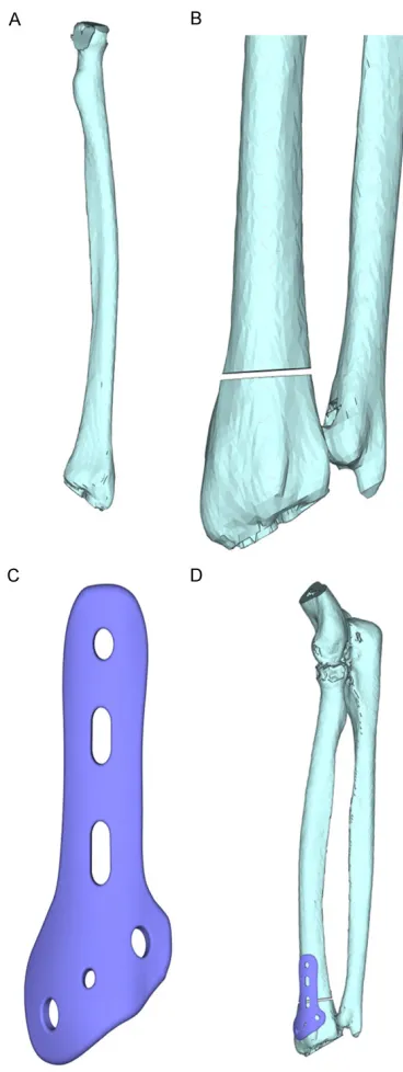
We selected the left arm sample of one healthy male volunteer (28 years old with 173 cm and 67 kg, no medical history of elbow joint, fore-arm injuries) who had physical examination in The Fifth Hospital of Harbin in April, 2016. CT scanning was conducted along the radial axis direction; the CT images of cross sections were input into the computer, so as to obtain the every layer cross section image of the radius. Software 3D-DOCTOR (3.5 version) was used to obtain the rebuilt 3-D visualization model of distal radius (Figure 1A).
Construction of 3-D stereo model after the DRF
The normal model was used; the distal radius 1 cm position was selected to simulate the frac-ture phenomena; the software 3D-DOCTOR (3.5 version) was used to get the rebuilt 3-D model of DRF (Figure 1B). In ProE 5.0, the 3-D model of AO non-bridge fixation structure was set up (Figure 1C), through simplification it was fitted together with the built 3-D model of DRF, so as to obtain the 3-D model of distal radius equipped with non-bridge fixation structure (Figure 1D).
3-D finite element analysis and calculation
[image:2.612.88.272.69.558.2]The constructed normal radius 3-D visualiza-tion model and the 3-D stereo model of DRF equipped with AO NBEF were imported into large finite element analysis method, softwa- re ASNSYS 10.0. The optimization mainly included the related parameter setting, tional assumption, meshing, boundary condi-tion determinacondi-tion and loading. When some motions of normal forearm were simulated, 3-D finite element analysis was conducted towards the stress transmission and distribution condi-tions of distal radius; the radius finite element model under healthy condition was taken as the basic biomechanical reference on radius research.
Figure 1. Three-dimensional stereo model after non-bridge external fixation of distal radius fracture. A: Radius three-dimensional visualization model; B: Distal radius fracture model; C: AO non-bridge exter
Parameter setting
On conducting radius stress analysis, its elas-ticity modulus was set to be 13,850 MPa, and
[image:3.612.89.374.106.587.2]simulated when the model was compressed or stretched, resulting in compression or stretch-ing of the radius [16]. At the same time, torsion load vertical moment was exerted on the inside
Table 1. Material characteristic parameters of several tissues
Tissue elasticity (Gpa)Modulus of Poisson’s ratio rigidity (g/cmModulus of 2) Cortical bone 14.8 0.31 6.6*107 Cancellous bone 1.5 0.33 5.4*107 Interosseous membranes 0.9 0.43 3.2*107 Ligament 0.53 0.49 1.8*106
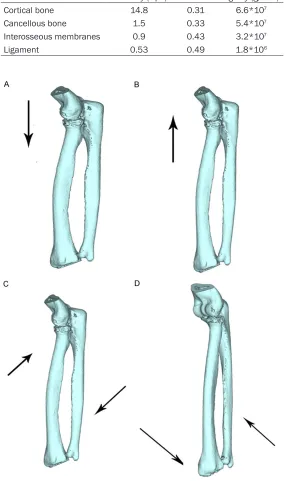
Figure 2. Normal radius model conditions under all operating conditions. A:
Under the operating condition of contraction; B: Under the operating condi
-tion of stretching; C: Under the operating condi-tion of internal rota-tion; D: Under the operating condition of external rotation.
its Poisson ratio was set to be 0.35.
Conditional assumption
The distal radius is mainly made up of cancellous sub-stance. Its stress-strain rela-tion under the condirela-tion that stress doesn’t surpass its ulti-mate strength is quite similar with many engineering materi-als, and manifests linear rela-tion. The model built included several tissues: bone (cortical bone and its internal cancel-lous bone), ligament and inter-osseous membranes. The material assumption involved in radius model belongs to even and homodromous elas-tic materials. Its material char-acteristics are as follows in
Table 1.
Meshing
The radius model built was input into ANSYS 10.0 to con-duct 3-D finite element unit partition. The grid size param-eter setting adhered to the principle of considering both elaboration and economy; the grid established had 57,320 cells and 85,782 nodes [15].
Boundary conditions, loading and observation index
and outside of radius and the moment was 1 NM. In this way, we could simulate the operat-ing conditions of external or external rotation and observe stress distribution, transmission and displacement occurrence under such an operation condition [15].
model fixed by AO NBEF
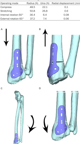
[image:4.612.91.365.93.584.2]Loading was conducted with the four load con-ditions in 2.1, so as to obtain the following (Figure 3). They were respectively (Figure 3A) force condition under the operating condition
Table 2. Stress distribution and displacement on radius and ulna under the loads of all operating conditions
Operating mode Radius (N) Ulna (N) Radial displacement (mm) Compress 48.5 22.1 0.1
Stretching 50.8 26.8 0.6 Internal rotation 60° 36.4 6.4 0.08 External rotation 60° 37.2 7.4 0.06
Figure 3. Force condition of AO non-bridge distal radius fracture model un
-der all operating conditions. A: Un-der the operating condition of contrac
-tion; B: Under the operating condition of stretching; C: Under the operating condition of internal rotation; D: Under the operating condition of external
rotation.
Results
The stress distribution and displacement conditions of normal radius were simulated under four operating condi-tions
The force conditions under four operating conditions can be seen in Figure 2. The stress intensity and its distribution on the radius and ulna joint sur-face under all the operating conditions can be seen in
Table 2.
Under the load, the stress con-centrated on the junction between cancellous bone and cortical bone of the radius as well as the radial neck. It often showed the condition that there was stress concentration anomaly on some position and then the general stress tended to distribute more evenly. And it conformed to the fact that the DRF has the highest occur-rence rate in clinical practice. Comparison was made on the radioulna stress distribution and displacement conditions under different operating con-ditions. The discovery indicat-ed that the stress on radius was more concentrated un- der contraction and stretching states, especially under stret- ching state, the displacement of radius could reach 0.6 mm. In contrast, under the states of internal rotation and external rotation, the stress distribution was relatively homogeneous and the displacements occu- red were quite small.
of contraction, (Figure 3B) stress condition under stretching, (Figure 3C) stress condition under internal rotation and (Figure 3D) stress condition under external rotation.
Table 3 is about the results of stress distribu-tion and displacement condidistribu-tion test of the DRF model fixed by AO NBEF under four load conditions.
Under the four operating conditions, displace-ments seldom took place, which proved AO non-bridge fixation had sound stress tolerance, stress-strain basically took on linear relation and the radius could recover to the normal shape after unloading. Under the operating condition of stretching, displacement was rela-tively larger and the maximum could reach 1 mm. The basic internal and external rotation stress focused on the steel plate, and there was seldom displacement. Under contraction and stretching, stress mainly focused on the 2/3 part of trailing arm of fixed support. Under internal rotation and external rotation, stress mainly focused on the 2/3 part of oblique arm and trailing arm of fixed support, distributed more evenly and comprehensively concentrat-ed on the proximity of set screws. Under the above operating conditions, AO non-bridge fixed support could play a sound stress shield-ing role. Although it may have a poor resistance to stretching, generally speaking, it didn’t affect the fixation effect.
Discussion
DRF is one of the common fractures in the clin-ic, and wrist joint is one of the important fine joints of human body. According to some litera-ture, under normal condition, about 80% axial load is supported by distal radius; the left 20% is supported by triangular cartilage and capitu-lum ulnae [17, 18]. If DRF isn’t dealt with in time or treated improperly, the transmission system of load will collapse. The radiocarpal joint will
finite element method makes use of CT image and professional software to draw the normal radius 3-D finite element model and conduct value assignment towards all the parts accord-ing to the elasticity modulus and Poisson’s ratio obtained by historical research data. This could improve the accuracy of simulation result and approach the real result as much as possible. In addition, through the load test, the effective-ness of the model is validated; the result coin-cides with the experimental research results in China and abroad [19, 20].
This experiment applies the finite element anal-ysis method to discuss the stress distribution and displacement conditions of the DRF model fixed by AO NBEF under the four operating con-ditions. In comparison to the stress distribution condition of a normal radius model, the research reveals that AO non-bridge fixation DRF model reduced stress concentration under the operating conditions of contraction and stretching. It indicates that AO NBEF possesses certain stress shielding function towards DRF and can play a role of treating radius fracture. And this is quite similar with the result of a frac-ture 3-D finite element analysis abroad [21-23].
It is feasible to adopt finite element analysis to set up a DRF model fixed by AO NBEF and make load stress analysis. But the model built in this thesis still has inadequacies on conducting bio-mechanical analysis, for example, in order to simplify the model, the model material setting parameters are relatively singular, the material assumption is too homogenous and the model built doesn’t include the anatomical structures like muscular tissues.
In conclusion, with the deepening of finite ele-ment analysis, the finite eleele-ment analysis com-bining with the biomechanical analysis
applica-Table 3. Radioulna stress distribution and displacement of the AO non-bridge distal radius fracture model under the loads of all operat-ing conditions
Operating mode fracture model (N)Distal radius external fixation (N)Non-bridging Displacement (mm)
Compress 27.5 36.1 0.09
Stretching 29.8 40.8 1.0 Internal rotation 60° 11.3 26.1 0.02 External rotation 60° 10.4 27.5 0.01
get pains and even lead to insufficient grip strength. The distal radioulnar joint will have an incongruous occurrence; there is very obvious dynamics affec-tion towards wrist joint [2].
tion of NBEF DRF model will be more widely applied in clinical practice, possessing guiding significance towards the treatment of radius fracture.
Disclosure of conflict of interest
None.
Address correspondence to: Feng Wang, Depart-
ment of Orthopaedics, The Fifth Hospital of Harbin, No.27 Jiankang Road, Xiangfang District, Harbin
150040, Heilongjiang Province, China. Tel:
+86-13836188911; E-mail: [email protected]
References
[1] Lutsky KF, Beredjiklian PK, Hioe S, Bilello J, Kim N and Matzon JL. Incidence of hardware removal following volar plate fixation of distal radius fracture. J Hand Surg Am 2015; 40:
2410-2415.
[2] Lalone EA, Grewal R, King GJ and MacDermid JC. A structured review addressing the use of radiographic measures of alignment and the definition of acceptability in patients with dis
-tal radius fractures. Hand (N Y) 2015; 10:
621-638.
[3] Vosbikian MM, Ketonis C, Huang R and Ilyas AM. Optimal positioning for volar plate fixation of a distal radius fracture: determining the dis -tal dorsal cortical distance. Orthop Clin North Am 2016; 47: 235-244.
[4] Pundkare GT and Patil AM. Carpometacarpal joint fracture dislocation of second to fifth fin -ger. Clin Orthop Surg 2015; 7: 430-435.
[5] Lutz M, Wieland T, Deml C, Erhart S, Rudisch A and Klestil T. Arthroscopically assisted osteo
-synthesis of dorsally tilted intraarticular dis-tal radius fractures--technique and results. Handchir Mikrochir Plast Chir 2014; 46:
271-277.
[6] Strobel U, Tami I, Andreisek G, Giovanoli P and Calcagni M. Comparison of functional results with MRI findings after surgical treatment of transscaphoid perilunate fracture dislocations of the wrist: the role of scapholunate ligament lesions. Handchir Mikrochir Plast Chir 2014;
46: 169-176.
[7] McQueen MM. Redisplaced unstable fractures of the distal radius. A randomised, prospective study of bridging versus non-bridging external fixation. J Bone Joint Surg Br 1998; 80:
665-669.
[8] Obert L, Rey PB, Uhring J, Gasse N, Rochet S, Lepage D, Serre A and Garbuio P. Fixation of distal radius fractures in adults: a review.
Orthop Traumatol Surg Res 2013; 99: 216-234.
[9] Kang YK, Park HC, Youm Y, Lee IK, Ahn MH and
Ihn JC. Three dimensional shape
reconstruc-tion and finite element analysis of femur be
-fore and after the cementless type of total hip replacement. J Biomed Eng 1993; 15:
497-504.
[10] Lotz JC, Cheal EJ and Hayes WC. Fracture pre
-diction for the proximal femur using finite ele
-ment models: part II--nonlinear analysis. J Biomech Eng 1991; 113: 361-365.
[11] Parashar SK and Sharma JK. A review on ap
-plication of finite element modeling in bone
biomechanics. Perspectives in Science 2016; 8: 696-698.
[12] Morales-Orcajo E, Souza TR, Bayod J and Barbosa de Las Casas E. Non-linear finite ele
-ment model to assess the effect of tendon forces on the foot-ankle complex. Med Eng Phys 2017; 49: 71-78.
[13] Watson PJ, Dostanpor A, Fagan MJ and Dobson
CA. The effect of boundary constraints on finite element modelling of the human pelvis. Med Eng Phys 2017; 43: 48-57.
[14] Liao SX, Wang JH, Zheng YQ, Zheng G, Wei GJ, Xia H and Chen XH. Three-dimensional finite element analysis of a newly developed aliform internal fixation system for occipitocervical fu
-sion. Med Eng Phys 2016; 38: 1392-1398. [15] Lin CL, Lin YH and Chen AC. Buttressing angle
of the double-plating fixation of a distal radius fracture: a finite element study. Med Biol Eng
Comput 2006; 44: 665-673.
[16] Su JC, Zhang CC, Chen WH, Yu BQ, Wang JL, Xu SG, Ji F, Wu JG and Ding ZQ. Construction of three-dimensional model of anatomic distal radius memory connector and its memory bio
-mechanical significance. Chinese Journal of
Clinical Rehabilitation 2004; 8: 2066-2067.
[17] Magnus CR, Arnold CM, Johnston G, Dal-Bello Haas V, Basran J, Krentz JR and Farthing JP. Cross-education for improving strength and mobility after distal radius fractures: a ran
-domized controlled trial. Arch Phys Med
Rehabil 2013; 94: 1247-1255.
[18] Alluri RK, Bougioukli S, Stevanovic M and Ghiassi A. A biomechanical comparison of dis
-tal fixation for bridge plating in a dis-tal radius fracture model. J Hand Surg Am 2017; 42:
748.e1-748.e8.
[19] Chantarapanich N, Nanakorn P, Chernchujit B and Sitthiseripratip K. A finite element study of
stress distributions in normal and
osteoarthrit-ic knee joints. J Med Assoc Thai 2009; 92
Suppl 6: S97-103.
[20] Gislason MK, Stansfield B and Nash DH. Finite element model creation and stability consider
human wrist joint. Med Eng Phys 2010; 32:
523-531.
[21] Synek A, Chevalier Y, Baumbach SF and Pahr DH. The influence of bone density and anisot
-ropy in finite element models of distal radius fracture osteosynthesis: evaluations and com
-parison to experiments. J Biomech 2015; 48:
4116-4123.
[22] van Rietbergen B and Ito K. A survey of micro-finite element analysis for clinical assessment of bone strength: the first decade. J Biomech
2015; 48: 832-841.
[23] Edwards WB and Troy KL. Finite element pre
-diction of surface strain and fracture strength at the distal radius. Med Eng Phys 2012; 34: