Abstract— Location Management in mobile communication is concerned with tracing and f inding mobile terminal (MT). The main issue is to deal with the moving MT. This paper presents a new analytical method to calculate the perf ormance by considering the movement of the MT both within and outside the cluster of location areas. The proposed analytical method is eff ective to the MT with high mobility and small LA.
Index Terms—Location Area (LA), Overlapped Super Location Area (OSLA), Personal Communication Services (PCS), Super Location Area (SLA),
I. INTRODUCTION
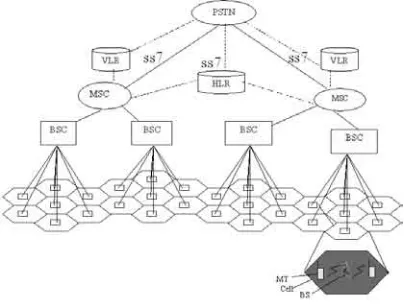
Personal communication service (PCS) is one of the standard widely used in location management [3-6] among existing standards. The typical architecture of the PCS network is shown in Fig. 1.1. The architecture has two database HLR and VLR. The mobile switching center (MSC) associated with a specific VLR is in charge of several base station controllers (BSCs), lower control entities which in turn control several base stations (BSs). The MSCs are connected to the backbone wired network such as public switched telephone network (PSTN). The network coverage area is divided into smaller cell clusters called location areas (LAs).
The visitor location register (VLR) stores temporarily the service profile of the MT roaming in the corresponding LA. The home location register (HLR) stores permanently the user profile and points to the VLR associated with the LA where the user is currently located. Each user is assigned unambiguously to one HLR, although there could be several physical HLRs.
A base station periodically broadcasts its location area identifier (LAI), which is unique for each LA. When a MT enters
Chiranjeev Kum ar is with the Department of Computer Science & Engineering, Indian School of Mines University, Dhanbad – 826004, Jharkhand (INDIA), as an Assistant Professor. Email: [email protected]
Koteswararao Kondepu was with the Departm ent of Com puter Science & Engineering, Indian School of Mines University, Dhanbad – 826004, Jharkhand (INDIA), as a M.Tech. Student. Currently he is working with TCS, India. Em ail:
Rajeev Tripathi is with the Department of Electronics & Communication Engineering, Motilal Nehru National Institute of Technology, Allahabad,Uttar
[image:1.595.331.533.388.540.2]a new LA, it receives a different LAI. Then, the MT sends a registration message to a new VLR. The new VLR sends a registration message to the HLR. Then the HLR sends a registration cancellation message to the old VLR and sends a registration acknowledge message to the new VLR. Now the HLR points the new VLR that has service profile and location information of the MT. This procedure is called the location update. When a call to a PCS user is detected, the corresponding HLR is queried. Once the HLR corresponding to the MT has been queried, the VLR/MSC currently serving the MT is known. Then paging is done through the LA where the MT is currently located.
Fig. 1.1 The Cellular Architecture in PCS Network
The location update cost consists of the update cost of HLR and that of VLR. Since the HLR is connected to many VLRs as shown in Fig. 1.1, reducing the traffic with the HLR becomes an important issue to reduce the whole location update costs. This paper proposes to employ a hierarchical structure to reduce the location update cost of the HLR.
In the PCS system, both VLR and HLR are updated whenever a MT enters a new LA. So the location updates tend to occur frequently in the boundary cells of LAs. This is the drawback in PCS system. In [1], the author has proposed a hierarchical structure to reduce the location update cost.
The rest of the paper is organized as follows. Section 2 describes the related work. Section 3 includes proposed analytical method for SLA and OSLA. Section 4 contains results and observations of proposed analytical method. Finally, Section 5 presents conclusions.
An Efficient Analytical Method for Location
Management Strategy in Cellular Mobile
Networks
II. THE RELATED WORK A. Super Location Area (SLA) Scheme
[image:2.595.315.540.88.307.2]In [1], the author has proposed a super location area, which is a group of LAs. The size of SLA may be various. The cellular architecture for the SLA scheme is shown Fig. 2.1.
Fig. 2.1 The Cellular Architecture Em ploy ing the SLA
[image:2.595.47.279.178.324.2]The Fig. 2.1 shows the case in which each LA and SLA contains 7 cells and 19 LAs, respectively. The notation LAi-j represents the cells belonging to an LA j in an SLA i. Each MSC/VLR covers a specific SLA. The VLR is updated while a MT roams between different LAs within an SLA. Both of the VLR and the HLR updates happen only when the MT enters a new SLA. Modified LAI structure is shown in Fig. 2.2.
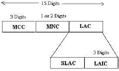
Fig. 2.2.The Hierarchical Structure of the LAI
The conventional LAI was divided into three parts: the mobile country code (MCC), the mobile network code (MNC), and the location area code (LAC). The SLA scheme uses a hierarchical structure by dividing the LAC into two parts again: the super location area code (SLAC) and the location area identification code (LAIC).
[image:2.595.71.264.446.562.2]In SLA scheme, both of the VLR and HLR updates occurs when a MT moves to a different SLA like the path from D to H in Fig. 2.3. That is, the HLR updates also happen frequently in the boundary LAs of the SLAs. In [2], the author has proposed one more hierarchical structure to reduce the location update cost.
Fig. 2.3.Moving Path of M T in the SLA
B. Overlapped Super Location Area (OSLA) Scheme
This scheme employs overlapping location areas, which has the common boundary LAs between different SLAs. The overlapping LAs are colored areas in the Fig. 2.4. The overlapping borders consist have two-fold or three-fold overlapping LAs. The overlapping LAs belong to all SLAs associated with them. The two-fold overlapping LA is included in the two SLAs and two different LAIs are broadcasted in the LA. The three-fold overlapping LA is included in three different SLAs and three LAIs are broadcasted in the LA. Note that the overlapping LAs are duplicately managed by corresponding all MSCs/VLRs. As an example, the SLA9 out of SLAs shows an SLA with overlapping LAs in detail. When a MT enters into the overlapping LA, it must register only one LA out of the overlapping LAs.
[image:2.595.316.551.561.715.2]Fig. 2.5. Moving path of a MT in the OSLA
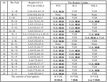
Table 1: Comparison of Location Update Cost
In overlapping location areas, if one out of the currently broadcasted LAI belongs to the same SLA as that of the previously registered LA, a MT registers to it. In Fig. 2.5, if a MT arrives at location D and H, the MT registers to LA4-3 out of two LAs and LA1-5 out of three LAs, respectively. The LA4-3 and LA1-5 are LAIs belonging to the same SLA as LAI of the previously registered LA, respectively. In this approach,
both of the VLR and the HLR are updated only when a MT moves to the LA that belongs to the new SLA and does not belong to the old SLA at the same time. Particularly, in case of a path from location H to I, the MT has to register to either LA5-2 or LA2-8 as shown in the 8th row in Table 1. The decision of such registration is made by a random selection. According to the decision, the location update cost is different as
The Register Update ID The Path Registered LA
PCS, SLA/OSLA PCS SLA OSLA
1 A->B LA4-14/LA4-14 VLR, HLR VLR VLR
2 B->C LA4-14/LA4-14 None None None
3 C->D LA4-3/LA4-3 VLR, HLR VLR VLR
4 D->E LA1-7/LA1-16 VLR, HLR VLR, HLR VLR, HLR 5 E->F LA5-11/LA1-6 VLR, HLR VLR, HLR VLR 6 F->G LA1-6/LA1-15 VLR, HLR VLR, HLR VLR 7 G->H LA5-12/LA1-5 VLR, HLR VLR, HLR VLR 8 H->I LA-13/(LA2-8 or LA5-2) VLR, HLR VLR VLR, HLR 9 I->J LA5-19/LA5-14 VLR, HLR VLR VLR, HLR or VLR
10 J->K LA5-15/LA5-4 VLR, HLR VLR VLR
11 K->L LA5-15/LA5-4 None None None
12 L->M LA5-5/LA6-17 VLR, HLR VLR VLR, HLR 13 M->N LA6-9/LA6-19 VLR, HLR VLR, HLR VLR 14 N->O LA9-1/LA6-16 VLR, HLR VLR, HLR VLR 15 O->P LA6-8/LA6-15 VLR, HLR VLR, HLR VLR
16 P->Q LA6-7/LA6-5 VLR, HLR VLR VLR
17 Q->R LA6-6/LA7-17 VLR, HLR VLR VLR, HLR
18 R->S LA6-16/LA7-10 VLR, HLR VLR VLR
19 S->T LA6-17/LA6-14 VLR, HLR VLR VLR, HLR
20 T->U LA6-19/LA6-3 VLR, HLR VLR VLR
The num ber of total updates 18 VLR, 18 HLR
18 VLR, 7 HLR
[image:3.595.123.471.374.640.2]shown in the 9th row in Table 1.
In [1][2], the authors has proposed analytical methods for performance evaluation of SLA and OSLA schemes by considering the special case i.e., when the MT moves out of the cluster of SLA’s. The movement within the cluster (e.g., from one super location area to another super location area of the same cluster) is not considered in [1] and [2]. As per the analytical method [1][2], the result for s=2 (the size of SLA) and d=2 (the size of LA) comes out to be 9 HLR updations, but if the movement within and outside of the cluster is considered (which is very essential for the exact evaluation of location updates) then the total number of HLR updations comes to be 15.
III. PROPOSED ANALYTICAL METHOD FOR SLA & OSLA SCHEME
The proposed method considered all possible movements within and outside the cluster of SLA and OSLA scheme. The number of HLR updation is calculated on the basis of proposed analytical method.
[image:4.595.328.533.148.655.2] [image:4.595.55.282.381.675.2]The notations used in this proposed method are depicted in Table 2.
Table 2. The Notations Used in Analy tical Method
K
The average number of MTs in a cell d The size of LAs The size of SLA
Nc The number of cell in an LA: 3d2-3d+1 Nla The number of boundary cells in LA: 6(d-1) NSla The number of LAs in SLA: 3s2-3s+1
NSc The number of cells in an SLA: (3s2-3s+1)(3d2-3d+1)
NSbc The number of boundary cells in an SLA: 6{3d-2+(s-2)(2d-1)}
N The total number of MTs in LA Ns The total number of MTs in SLA
LA
R
The total location update rate for the given LASLA
R
The total location update rate for given SLA
OSLA
R
The total location update rate for the given OSLA
MS
R
The average location update rate per MTTd
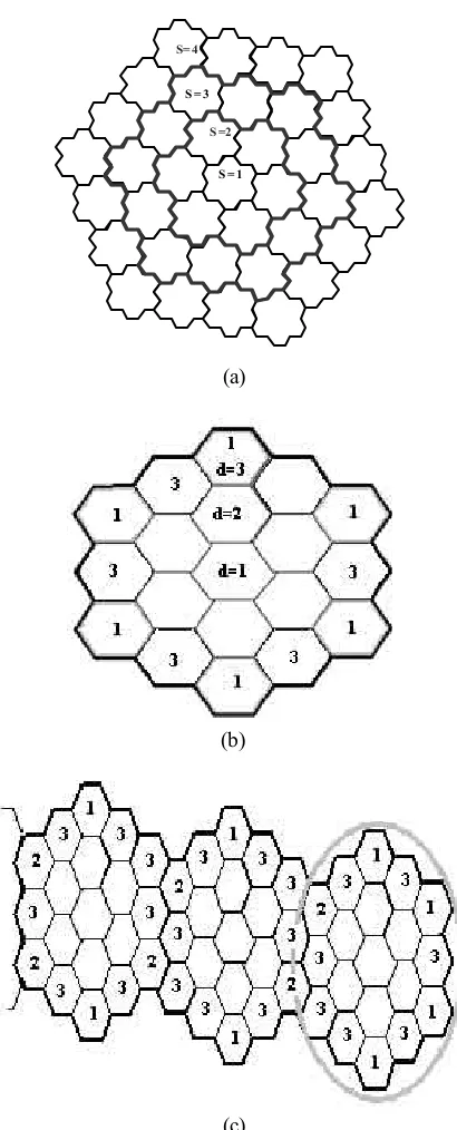
The average dwell timeFig. 3.1 gives the information to develop the analytical method. The number of rings of LA’s is represent by the size of SLA with notation s, as shown in Fig. 3.1(a). The number of rings of cells is represented by d, which is the size of LA, as shown in Fig. 3.1(b). The method assumes that the MT moves
to one of the neighboring cells with probability 1/6.
The Fig. 3.1 (b, c) shows the movement of MT from the cell, marked 1, 2 and 3, to another neighboring cell with the probability of 3/6, 1/6 and 2/6, respectively. This results to HLR updates.
S = 1 S =2 S = 3 S= 4
(a)
(b)
(c)
Fig. 3.1 The Boundary cells in an LA or SLA
All generalized formulas for LA, SLA and OSLA are given below:
[image:4.595.57.280.385.674.2]K
1)
3d
d 2
(3
K
Nc
N
=
⋅
=
−
+
⋅
The total location update rate for the given LA is
R
LA, which iscalculated as
Td
1
K
1)
(2d
Td
1
K
1}
6
3
2)
(d
6
2
6{
R
LA=
⋅
−
+
⋅
⋅
⋅
=
−
⋅
⋅
(ii)
So the average location update rate for the given LA is:
Td
1)
3d
(3d
1)
(2d
R
MS 2⋅
+
−
−
=
(iii) The total number of MTs in SLA is Ns, which is calculated asK
1)
3d
2
(3d
1)
3s
s 2
(3
K
Nsc
Ns
=
⋅
=
−
+
⋅
−
+
⋅
(iv) The number of boundary cells in SLA is Nsbc, which is
calculated as
(v)
1}
s
1)
)(d
1
6{(2s
1)]
-(d
6
6
3
1}
1)
-(d
6
6
2
2){
6[(s
Nsbc
−
+
−
−
=
⋅
⋅
+
+
⋅
⋅
−
=
(v) The total location update rate for the given SLA isR
SLA,which is calculated as
(vi)
Td
1
K
1)
(2d
1)
(s
5
Td
1
K
1)}}
(s
6
1
1)
(d
1)
(s
6
2
{
2)}
(s
6
1
1)
(s
6
3
2}
s
2)
3)(d
{(2s
6
2
{
1)
(s
6
1
s
6
3
1}
s
2)
1)(d
{(2s
6
2
6{
R
SLA⋅
⋅
−
⋅
−
⋅
=
⋅
⋅
−
⋅
+
−
⋅
−
⋅
+
−
⋅
+
−
⋅
+
−
+
−
−
⋅
+
−
⋅
+
⋅
+
−
+
−
−
⋅
=
(vi)So the average location update rate for MT in SLA is (From (iv) & (vi)):
Td
1)
3d
2
(3d
)
1
3s
2
(3s
1)
(2d
1)
(s
5
Ns
R
R
MS SLA⋅
+
−
⋅
+
−
−
⋅
−
⋅
=
=
(vii) The total location update rate for given OSLA isR
OSLA, whichis calculated as
} { } { } { Td 1 K 3 s 1) (d 2) (3s 4 2 1 Td 1 K 4) (2d 1) (s 2 1 2) (d 1) (2s 6 2 s 1) (s 2 1 1) (s 6 1 6 3 6 R ] [ OSLA ⋅ ⋅ + − − ⋅ − ⋅ = ⋅ − ⋅ − ⋅ + − ⋅ − + + − ⋅ + − ⋅ = ⋅ (viii)
So the average location update rate per MT in OSLA is (From (iv) & (viii)):
Td
1)
3d
2
(3d
1)
3s
2
2.(3s
3
s
1)
(d
2)
4.(3s
Ns
R
R
MS OSLA⋅
+
−
⋅
+
−
+
−
−
⋅
−
=
=
(ix)IV. RESULT S AND OBSERVAT IONS
In order to evaluate the performance of the proposed analytical method for SLA and OSLA schemes, the various cases are considered:
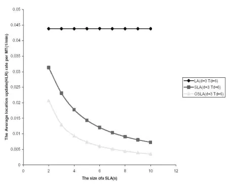
[image:5.595.321.545.525.709.2]Case 1: For d=3 & Td=6
Fig. 4.1 Update Rate of HLR According to the size of the SLA
(i)
In the proposed analytical method total number of location updations in SLA is greater than OSLA. The LA updation is always constant whatever the size of super location area i.e. LA is independent of size of SLA. From Fig. 4.1 shows, if the size of SLA is small then the larger decrement of average HLR update for every MT.
[image:6.595.53.283.196.382.2]Case 2: For d=6 & s=2
Fig. 4.2 Update Rate for HLR According to the size of LA
If the size of LA changes then there is a change in number of location updations. Location updations are inversely proportional with the size of LA. With the increment of the LA; the differences between LA, SLA and OSLA updations are decreased. If the size of LA and SLA is small then the large decrement in the average location update rate (HLR) per MT.
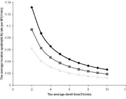
Case 3 : For d=3 & s=2
Fig. 4.3 Update Rate according to the average dwell tim e
The smaller the dwell time and the size of location area
becomes, the larger decrement of average HLR update per MTs. Consequently, the proposed analytical method is effective to the MT with high mobility and in small divided LA.
V. CONCLUSION
Mobility management has widely been recognized as one of the most important and challenging problems for a seamless access to wireless networks and mobile services. PCS network employ a mobility management mechanism for locating MTs and for maintaining their sessions while they are moving from place to place.
The concept of SLA and OSLA schemes have been used to reduce the number of location updations in HLR, while MT moves from one place to another place.
The problem was identified as to form an analytical method to calculate the number of updation to be done while MT moves within and outside the cluster. An analytical method is developed considering movement of MT within and outside of the cluster.
REFERENCES
[1] In-Hy e Shin and Gy ung-Leen Park, “On Em ploy ing Hierarchical Structure in PCS Networks,” Lecture Notes in Com puter Science, vol 2, #2668, pp. 155-162, May 2003.
[2] In-Hy e Shin, Gy ung-Leen Park, and Kang Soo Tae “An Effective Location Managem ent Strategy for Cellular Mobile Network”, Lecture Notes in Com puter Science, 3480, pp. 478-487, 2005.
[3] Yigal Bejerano, “Efficient Mobility Managem ent Schem es for Personal Comm unication Sy stems”, Research Thesis, Israel Institute of Technology , ELOL, Septem ber 2000.
[4] Jie Li, Yi Pan, Yang Xiao, “A Dy nam ic HLR Location Managem ent Schem e for PCS Networks,” IEEE INFOCOM 2004.
[5] T X Brown, S Mohan, “Mobility Managem ent for Personal Comm unications Sy stems,” IEEE Trans. On Vehicular Technology, Vol 46, No. 2, pp. 269-278, May 1997
[image:6.595.62.283.532.705.2]