Running COLA on Embedded Systems
Wolfgang Haberl
∗Michael Tautschnig
∗Uwe Baumgarten
∗Abstract—Model driven development has become state of the art in embedded systems software design. To take the resulting models to the designated hard-ware platform, automated code generation is sought for. The code obtained thereby must match the se-mantics of the model as closely as possible.
In this paper we show how to map models specified using the Component Language (COLA) [1] to C code in an automated manner. In addition we present our concepts for interfacing the effective hardware plat-form, which in case of embedded systems means the interaction with sensors and actuators.
Using a prototypical implementation of the code gen-erator, we validated our approach on a case study us-ing LEGOR
MindstormsTM, which embody all char-acteristics of embedded systems. This case study in-cludes benchmarks comparing the automatically gen-erated code to a hand-written version offering the same functionality.
Keywords: embedded systems, component-based mod-els, automated code generation
1
Introduction
Today, roughly 90% of all processors are part of embed-ded systems [2]. In many cases, these systems are em-ployed as, at least, parts of mission-critical control sys-tems that need to conform to various safety requirements. To meet these goals, model driven development (MDD) using component-based languages is widely accepted as the most suitable approach. Therefore, rapid prototyp-ing, but also the implementation of production level ap-plications is usually performed using graphical modeling languages. On the one hand, these models can be sur-veyed more easily by developers than the textual repre-sentation in code. On the other hand, graphical model-ing formalisms may hide error-prone language constructs, e.g., pointer arithmetic or type casts, and thus prevent unchecked memory access by the user.
1.1
Related work
Being the favorite approach, there is extensive tool sup-port for graphical modeling, e.g., MATLAB/Simulink, ASCET-SD, or SCADE, which is based on Lustre [3]. Furthermore, the Unified Modeling Language (UML) has become an industry standard that includes means for
∗Institut f¨ur Informatik, Technische Universit¨at M¨unchen, 85748
Garching, Germany,{haberl, tautschn, baumgaru}@in.tum.de
component-based modeling. Initially targeted at avionic systems, the Architecture Analysis and Design Language (AADL) [4] also offers well-defined models aimed at in-dustrial applications.
In a tool-backed MDD process, however, not only be-havioral modeling is sought for, but several views of the complete system must be distinguished. Following the nomenclature of Pretschner et al. [5], behavioral models form the logical architecture. The description of the tar-get hardware platform and other non-functional require-ments then comprise the technical architecture. The lat-ter is usually excluded in the modeling formalisms men-tioned above, or rather, focused on with a lack of de-scription of the logical layer. This kind of lower abstrac-tion is applied, e.g., in the Metropolis project [6] and the CARAT toolkit [7]. An approach aiming at both layers is that of the VERTAF framework [8].
COLA, the Component Language [1], initially also
fo-cused on the logical layer. We are currently extend-ing it to include a hardware model and further means to describe the technical architecture in a consistent formalism. Whenever a platform description is avail-able, executable code may be generated from the be-havioral (graphical) models. Examples of such compil-ers include TargetLink, Real-Time Workshop/Embedded Coder, ASCET-SC, and SCADE Drive. An overview and comparisons of these tools have been presented by Reuter [9] as well as Wybo and Putti [10].
1.2
Automated code generation
As included in the requirements expressed by Whalen and Heimdahl [11], ensuring correctness of the translation re-quires both the source and the target language to have a rigorous formal semantics. While this is hardly viable for the target language C, our source languageCOLA
pro-vides these. Consequently, we only rely on a subset of C and a template-like set of transformation rules such that preservation of behavior of the generator remains easy to check. At this point it should be noted that COLA
has a slender syntax and thus requires only a small num-ber of transformation rules. The elements of COLAare
introduced in Section 2.
1.3
Organization
In the following we first give a short introduction to
models to C code are described. The steps required to effectively run the generated code on a specific target platform are outlined in Section 4. The results on a case study are presented in Section 5, including considerations of the code efficiency. We conclude with an outlook on possible enhancements.
Throughout the paper we use parts of the model of the case study to illustrate the abstract transformation steps.
2
Overview of COLA
The key concept ofCOLAis that ofunits. These can be
composed hierarchically, or occur in terms ofblocks that define the basic (arithmetic) operations of an application.
Each unit has a set of typed ports describing the inter-face. These ports form the signature of the unit, and are categorized into input and output ports. Units can be used to build more complex components by building a network of units and by defining an interface to such a network. The individual connections of sub-units in a network are calledchannels and connect an output port with one or more suitably typed input ports.
In addition to the hierarchy of networks, COLA
pro-vides a decomposition into automata (i. e., finite state machines, similar to Statecharts [12]). If a unit is decom-posed into an automaton, each state of the automaton is associated with a corresponding sub-unit, which deter-mines the behavior in that particular state. This defini-tion of an automaton is therefore well-suited to partidefini-tion complex networks of units into disjoint operating modes (cf. [13]), whose respective activation depends on the in-put signals of the automaton.
The collection of all units forms aCOLAsystem, which
models the application, possibly including its environ-ment. Such a system does not have any unconnected input or output ports as there would be no way to pro-vide input to systems. For effective communication with the environment not describable within COLA, sources
andsinksprovide connectors to the underlying hardware.
2.1
Semantics
InCOLA, as a synchronous dataflow language, it is
as-sumed that operations start at the same instant of time and are performed simultaneously with respect to data dependencies. The computation of the system over time can be subdivided into discrete steps, called ticks, and the execution is performed in a stepwise manner over the discrete uniform time-base. The data dependencies are implied by the employed channels. At each step a unit emits new values to the channels connected to its out-put ports. These values become available immediately for ports connected to the reading side of the channel.
To retain data for a series of ticks, a concept ofdelays is
introduced. These blocks model memory by saving the actual input value and providing the input of the previous tick of the global clock at the output port. For initial use, there is a default value specified in the model.
2.2
Stateful vs. stateless units
In the course of computation a unit may act differently depending on its history. Such units are considered state-ful. InCOLAonly delays and automata retain
informa-tion of previous computainforma-tions, whereas all other kinds of units are stateless. Note that an instance of a unit containing a stateful element becomes stateful as well.
3
Coding basic model elements
In the following we will describe the transformation of COLA elements into C code. The mapping is exempli-fied presenting COLA diagrams and the according code snippets from our case study.
3.1
Units and signatures
For each unit found in the given system, the code gener-ator creates a C function with an appropriate signature. As COLA units may carry more than one output port in their signature, the resulting code has to offer an equiva-lent concept. We decided to include a variable of appro-priate type for each input and output port of the unit in the function’s signature. The C types corresponding to the type names used in the model are therefor predefined in the code generator. All variables are passed as pointers i.e., following the call-by-reference paradigm. In case of input ports this saves memory when complex data types are used, as the pointer always uses a fixed amount of memory independent of the dimension of the data type pointed to. Plus, for output ports, this is the only way to allow for multiple return values in C. In addition to these variables each signature of a stateful unit includes a struct named unit state. This struct keeps the actual state, e.g., of delays or automata. Details on the preservation of the actual state are given in Section 4.1. If neither the unit itself, nor any of its sub-units are stateful, the state struct is superfluous and thus omitted.
ETIKETT <net_ACC>
DEV_A_ MOTOR DEV_A_ DISPLAY
net_radar
net_ACC_on_off net_rotation
net_ui
mode
s_user
s_act
dist
acc_disp
[image:3.595.54.288.76.199.2]s_mot
Figure 1: Thenet ACCdiagram
3.2
Networks
The body of a generated C function implements the re-lated unit’s behavior. For a network this means, that the generated function for each sub-unit included in the network is called. Of course the sequence of calls has to preserve the order induced by semantics of the data flow. To do so, the set of sub-units provided for the network is searched for units not dependent on other units in the network. Each such unit can instantly be inserted in the resulting C code and removed from the set. This is true for all units which are connected to an input port of the parent unit, to an output port of a unit already coded, or to a unit which represents a constant value or a de-lay. The described iteration over the set of sub-units is repeated until the set is empty. Then all sub-units are coded in a sequential order preserving the data flow se-mantics.
1 voidrun_module(overall_module_state *unit_state)
2 {
3 ints_act_0;
4 intdist_1;
5 intmode_2;
6 ints_user_3;
7 intacc_disp_4;
8 ints_mot_5;
9 net_rotation200399(&(unit_state->state_rotation200399_num0), &s_act_0);
10 net_radar200400(&(unit_state->state_radar200400_num1), &dist_1);
11 net_ui200398(&(unit_state->state_userinterface200398_num2), &mode_2, &s_user_3);
12 net_acc_on_off200401(&(unit_state->state_acc200401_num3), &s_user_3, &s_act_0,
13 &dist_1, &mode_2, &acc_disp_4, &s_mot_5);
14 mw_write(DEV_A_MOTOR, *&s_mot_5);
15 mw_write(DEV_A_DISPLAY, *&acc_disp_4);
16 }
Listing 1: Thenet ACCcode
The code in Listing 1 is the code generated for the net-work from Figure 1. In the listing, the preservation of the causality according to the data flow can be seen. The formal semantics for the evaluation order of net-works is given in [1], Section 5.3. Looking at the ex-ample in Figure 1 there are three sub-units which can be evaluated independently, namely net ui, net rotation and net radar. Thus they are called first in the result-ing code, cf. lines 9 through 11 in Listresult-ing 1. The or-der of the three calls is arbitrary. After their process-ing, net acc on off can be executed and then finally DEV A DISPLAYandDEV A MOTORare written to. The re-sulting code is shown in lines 12 through 15 of Listing 1. The last two units are sinks, indicating interaction with
the hardware platform. We will go into details of sources and sinks in Section 4.2.
In addition to the evaluation order, the listing shows how each channel connecting two sub-units is realized. A vari-able is used to pass data from one function call to the next. It is being written to by the ancestor unit and read from by the descendant one.
3.3
Automata
InCOLAautomata provide a means of control flow. As
described in [1], an automaton’s behavior is implemented by the currently active state. Hence, firstly, the automa-ton has to know its current state and check for a necessary transition and, secondly, evaluate the implementing unit for the actual state. As the automaton’s actual state is stored from one invocation to the next, it is included in the automaton’s state struct.
WhileCOLA automata describe general Moore-type
fi-nite automata [14], the transformation to C code must yield deterministic behavior. In the actual prototype it is the responsibility of the modeler to employ only de-terministic automata. Further efforts are put in an au-tomated test for non-determinism while assuming data types with finite domains. Note that the problem is un-decidable in case of unbounded data types (undecidability of equivalence).
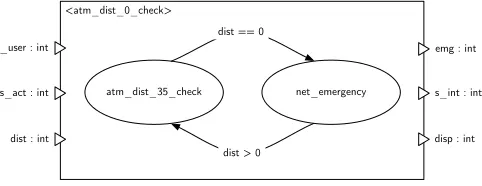
In Figure 2 a COLA unit implemented by an
automa-ton with two states is given. The states are named atm dist 35 check and net emergency. The actual state is changed either if the value for distequals zero or is greater than zero and depending on the actual state. Listing 2 shows the code for the automaton given in Fig-ure 2.
<atm_dist_0_check>
atm_dist_35_check net_emergency
dist == 0
dist > 0 dist : int
s_act : int
s_user : int emg : int
s_int : int
disp : int
Figure 2: Theatm dist 0 checkdiagram
[image:3.595.303.544.510.603.2]the transition is taken. Thus the automaton’s state is changed and the behavior of the target state is executed as exemplified in lines 9 through 15 and 21 through 27 respectively. If in contrast the guards evaluate to false, the behavior of the actual state is processed. In our ex-ample this is shown in lines 16 and 28. As mentioned in Section 3.1, the state struct is omitted for stateless units. An example of this approach can be seen in the calls in line 16 and 24.
In Listing 2 the analogousness of the automaton’s sig-nature and the sigsig-nature of its states is apparent. The variables passed to the automaton in line 1 are forwarded to the function calls in lines 12, 16, 24, and 28. The only variable differing is the unit state as it is distinct for each unit.
1 voiddist_0_check200695(state_dist_0_check200695 *unit_state,int*s_user_in_0, 2 int*s_act_in_1,int*dist_in_2,int*emg_out_0,int*s_int_out_1,int*disp_out_2)
3 {
4 intguard_result;
5 switch(unit_state->atm_state)
6 {
7 case0:
8 emergency_guard200747(s_user_in_0, s_act_in_1, dist_in_2, &guard_result);
9 if(guard_result)
10 {
11 unit_state->atm_state = 1;
12 atm_dist_35_check200787(&(unit_state->state_dist_gt_0_behavior200787_num1),
13 s_user_in_0, s_act_in_1, dist_in_2, emg_out_0, s_int_out_1, disp_out_2);
14 break;
15 }
16 net_emergency200764(s_user_in_0, s_act_in_1, dist_in_2, emg_out_0,
17 s_int_out_1, disp_out_2);
18 break;
19 case1:
20 dist_35_guard200730(s_user_in_0, s_act_in_1, dist_in_2, &guard_result);
21 if(guard_result)
22 {
23 unit_state->atm_state = 0;
24 net_emergency200764(s_user_in_0, s_act_in_1, dist_in_2, emg_out_0,
25 s_int_out_1, disp_out_2);
26 break;
27 }
28 atm_dist_35_check200787(&(unit_state->state_dist_gt_0_behavior200787_num1),
29 s_user_in_0, s_act_in_1, dist_in_2, emg_out_0, s_int_out_1, disp_out_2);
30 break;
31 }
32 }
Listing 2: Code foratm dist 0 check
3.4
Functional blocks and delays
Having only dealt with COLA elements allowing for hi-erarchical composition so far, we will now describe the coding of blocks. They form the base of the model repre-senting elementary operations and marking the endpoint of the hierarchy. We distinguish functional blocks and timing blocks, i.e., delays. The functional blocks allow for constants, and arithmetic and Boolean operations, while the timing blocks provide a means of storing values.
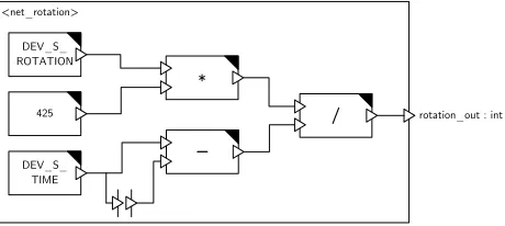
To avoid the function call overhead, all blocks are ex-panded inline instead of calling a function. An example of coding blocks and delays is given in Listing 3. It shows the code generated for the diagram in Figure 3. As can be seen, all units in this diagram are marked with a black tri-angle in the upper right corner, indicating a block. Again, two sources are included, the concept of which will be de-scribed in Section 4.2. Furthermore, a constant value of 425 is given. It is multiplied with the value delivered by the sourceDEV S ROTATIONand the result divided by the value calculated in the lower part of the diagram. The
<net_rotation> DEV_S_ ROTATION
425 DEV_S_
TIME
/
*
rotation_out : int
[image:4.595.313.543.76.179.2]_
Figure 3: Thenet rotationdiagram
according code is given in line 7 of Listing 3. The de-lay included in Figure 3 is depicted by a black and white square. This timing block functions as a one-step FIFO. It outputs the value given to it during the previous invo-cation of the network. Thus, in our example, the value of DEV S TIME is delivered. In change the data pending at its input port is stored for the next invocation. The two described working steps of the delay can be seen in lines 6 and 8.
1 voidrotation200399(state_rotation200399 *unit_state,int*rotation_out_0)
2 {
3 introtation_0;
4 inttime_1;
5 mw_read(DEV_S_ROTATION, &rotation_0);
6 mw_read(DEV_S_TIME, &time_1);
7 *rotation_out_0 = ((rotation_0 * 425) / (time_1 - (unit_state->delay200513)));
8 (unit_state->delay200513) = time_1;
9 }
Listing 3: Code fornet rotation
3.5
Prototypical implementation
For our prototypic implementation, the COLA model is represented using the OOMEGA1 framework. This
framework stores the model using an object oriented database and offers functions for accessing the model el-ements through a Java API. Thus our code generator is also realized in Java. Currently the code generator pro-duces a single task out of the model in question.
4
Running the generated code
The presented code generator implements a part of a model driven system realization demanded for future em-bedded real-time systems [15]. Assuming the use of a standardized middleware enables for the use of our com-piler in combination with various platforms. Thus the effort for coupling the application to the underlying hard-ware is no more demanded to be done separately for every program, but is shifted to the implementation of the mid-dleware. As this layer remains unchanged for every appli-cation, the complexity of the application is decreased and the development resources saved can be used to develop a high-quality middleware.
When generating code for embedded hardware, the ques-tion of how to execute the code arises. First of all, of
1
course, the code has to be compiled using a valid C com-piler for the intended target platform. But there are other prerequisites for enabling the applicability of the code. One important point is data retention for stateful tasks. Besides that, another point is the access of sensor and actuator values. In the following we will present our so-lutions to these problems using a middleware layer.
4.1
Preserving the actual state
Regarding COLA elements, two kinds can be distin-guished. Namely stateful and stateless elements. Cur-rently the only stateful constructs in COLA are delays and automata. A delay keeps its actual value from one invocation of the enclosing unit to the next. Analogously, an automaton maintains its actual state from one invo-cation to the next. In case of an automaton or network this is also true for all sub-units contained in any of their implementing units.
As we are generating tasks for the target operating sys-tem, we need to find a means of initializing and storing data. We address this problem by defining a struct for every unit containing its state, which retains the values of all contained delays and each automaton’s active state number. Further instances of the respective structs of all sub-units of the unit are included. We have a struct for the top-level unit, i.e., the system code is generated for. As stated before this struct contains nested structs for all stateful sub-units. During startup, the struct is initial-ized with default values specified in the model. Later on, this top-level struct is read from the middleware by the task at the beginning of every invocation. The modified struct is written back to the middleware at the end of the task. The middleware maintains an appropriate amount of memory for every task.
4.2
Interfacing sensors and actuators
It’s in the nature of an embedded system that a lot of hardware interaction has to be done. So, COLA and
thus the code generator as well, have to provide a way to interface sensors and actuators. To allow the use of an arbitrary number of such devices, we propose the use of a middleware. Its task is the mapping of logical addresses, which are in numeric format, to real hardware addresses as well as the subsequent hardware interaction.
Due to this abstraction the generated code uses mw read()andmw write()for any hardware interaction. The calls take the logical address of the device in ques-tion as a parameter. Regarding theCOLAmodel, such
a logical address is a unique name. The code genera-tor inserts this name as a constant into the function call. The middleware’s header file features according#define statements to replace the constants with numeric values.
The current implementation of COLA doesn’t provide
separate model elements to depict sensors and actuators.
For our example we solved this lack by using COLA
blocks with distinguished names. The operator was de-fined as “DEV S ” for sensor devices and “DEV A ” for ac-tuator devices respectively, followed by the device name. This requires the code generator to check for those string patterns. In a future version of COLA it is intended
to render devices more precisely by introducing separate model elements. Thus the risk of generating not properly working code because of malformed identifiers is reduced.
As another difference compared to regularCOLAblocks,
these device blocks have exactly one port. An output port for sensors, delivering the sensor’s values and an input port for actuators accepting the calculated value of the control loop algorithm. To avoid the possibility of race conditions, each sensor or actuator may only be inserted once into a COLA model. Since every device
features just one port, this demands the developer to ex-plicitly model the control of every concurrent hardware interaction.
5
Case study
To prove the practical viability of our approach, we did a case study using LEGOR MindstormsTM controllers as
hardware platform, equipped with the BrickOS2
operat-ing system. The demonstrator should realize the func-tionality of an adaptive cruise control (ACC) [16]. This is a control device for cars providing the functionality of keeping the car’s speed at a value set by the driver, while maintaining a minimum distance to the car driving ahead.
The presented example is an imitation of the concerns and requirements of automotive design, and does not rep-resent a real set of control algorithms for an actual prod-uct or prototype.
5.1
Functionality of the demonstrator
The intended functionality of the demonstrator includes the possibility to turn the ACC on and off. If the device is turned off, the motor speed set by the user is forwarded to the engine control without any modification. The display indicates the current ACC state. By engaging the ACC, the speed and distance regulation are activated. This includes the measurement and comparison of the pace set by the user and the actual measured car velocity. If the desired user speedsuserdiffers from the actual speed sact, the target speed for the motor control is corrected
by (suser−sact)/20. This results in a speed correction
of 5 percent of the difference between actual and desired speed. This regulation is used as long as no object is detected within 35 centimeters ahead of the car. If the distance drops below this threshold, the actual speed is continuously decreased by 5 percent. The minimum dis-tance allowed constitutes 15 centimeters. If the actual
2
distance is lower, the car performs an emergency stop. After either reducing speed or coming to a halt, the ACC should speed up the car smoothly again, if the obstacle is out of the critical region.
5.2
The ACC COLA model
The implementation of this functionality is severely in-fluenced by the hardware available. The used controller offers only two buttons available for control actions to the programmer. Further, three sensor and three actua-tor ports are present. For the demonstraactua-tor we use the two controller buttons for setting the desired user speed. A touch sensor is employed to switch the ACC on and off. The remaining two sensor ports are used to connect a rotation and an ultrasonic sensor. Two motors are con-nected to the actuator ports, while the third port was utilized to connect some brake lights.
The top-level network of the ACC COLA model is
shown in Figure 1. This network has no ports as all sensors and actuators used for the ACC’s op-eration are included in the network. Namely the buttons DEV S VIEW, DEV S PRGM, the rotation sensor DEV S ROTATION, the system clockDEV S TIME, the touch sensorDEV S TOUCHand the distance sensorDEV S RADAR can be seen. The actuators of the network are the con-troller’s display DEV A DISPLAY and the motor control DEV A MOTOR. As described in Section 4.2 these blocks are coded as mw_read() and mw_write() statements, e.g., the call to DEV A MOTOR would be transformed into mw_write(MOTOR, *value) where *value is the calcu-lated output for the motor speed. MOTOR and all other device labels are mapped to a numeral using define state-ments in a header file. A hand-written middleware then forwards the read and write calls to hardware driver calls provided by BrickOS, which in turn provide sensor values or modify some actuator state.
5.3
Code efficiency
Embedded systems typically provide limited amounts of memory and processing speed. Thus the code executed must be small and predictable in its memory usage. This applies to the amount of coded instructions as well as variables. To achieve this goal, the code generator uses call-by-reference wherever possible. As pointer variables have a fixed size, the memory footprint of each function call becomes independent of the data structures passed around. In case of complex data types, the usage of point-ers may even reduce the amount of memory needed and lower the execution time.
Another way to save memory is the employment of re-use, i.e., the size of the generated code is kept small by making use of already coded components. Thus, if a unit appears multiple times in a given model, it is only once trans-formed into a C function. This function is then called
every time the unit is referenced. Of course there is a separatestate_structfor each unit instance, in case of a stateful unit.
5.4
Benchmarking the ACC code
When working with generated code, efficiency aspects surely play an important role. Using any valid tricks the programmer is aware of, hand-written code may be then considerably smaller and faster. Consequently, the bene-fit of automatic code generation rather is its deterministic result. If (to a certain extent) behavioral correctness of the model has been established using techniques such a (correct) code generator will produce equivalently cor-rect code. Coding errors like unintentional casts, wrong pointer arithmetic and the like are avoided. Finally a ma-jor fraction of the potential performance draw backs are negligible due to optimizations performed by compiler.
0 0.5 1 1.5 2 2.5 3
O1 O2 O3
Runtime (ms)
Optimization Level
[image:6.595.311.541.294.415.2]handcoded generated generated (static fct’s)
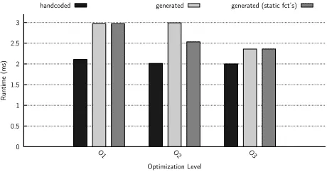
Figure 4: Benchmarking runtime results
To get an idea of the performance of the generated ACC code, we compiled it successively using the optimization levels O1, O2 and O3 of the GNU C compiler and checked the runtime results against the ones of a hand-coded ver-sion of the ACC. To give an impresver-sion of the quality of our manually coded version, we give the lines of code (LOC) as metrics. The hand-coded version fulfills the same functionality using 75 LOC, while the code gener-ator produced 249 LOC for the modeled ACC. The re-sulting binaries were compared regarding their execution times. To minimize errors in the measurement of the run-ning period induced by interrupts, context switches, etc., the ACC algorithm was called consecutively 100 times. We ran this benchmark 20 times for each optimization level. The averaged resulting times are given in Figure 4. The third bar in the diagram, named generated (static fct’s), indicates the values for a version of the generated code with all functions being declared static. As this al-lows the compiler to disregard the use of the functions from outside the binary, the functions calls can be re-placed by their implementation. Thus there is no jump to fulfill and thus the execution time decreases. As can be seen in the diagram, this effect makes most impact in case of the O2 optimization level.
generated code isn’t too far from the version implemented by hand. Especially when using the higher optimization levels of the compiler. There the generated code benefits even more than the alternative. At maximum optimiza-tion level, i.e., O3, the generated code even nearly reaches the execution times of the hand written version.
6
Conclusions
We presented a translation scheme of models given in the Component Language (COLA) to C code, and a
proto-typical implementation thereof. The formal semantics of
COLAand its small number of syntactic elements allow
for a transformation that fully retains the behavior of the model. The performance evaluation shows that, using an optimizing compiler, the execution time of the generated code only has an overhead of 20% when compared to a hand-crafted fully optimized version. We assume that such a low overhead immediately pays off as the gener-ated code is guaranteed to realize the behavior of the model, which has undergone functional validation.
Future enhancements of the code generator will focus on generating more efficient code, i.e., using less memory and CPU time, and integrating more syntactic elements as the vocabulary of COLA is still growing. Recent ad-ditions to COLA include the introduction of multidimen-sional data types, called records, and the use of distin-guished model elements representing sensor and actuator elements, namely sources and sinks. Additionally, the COLA standard library is intended to be filled with reg-ularly used units, e.g., integrator, counter, saturation, PID-regulator, etc. The code for these units can be gen-erated and saved for future code generation, thus avoid-ing to generate it more than once and speedavoid-ing up the transformation.
Another ongoing project is the use of a model checker for verification of COLA models. To facilitate this, the model is transformed into Promela code and checked using the SPIN [17] model checker. The generator for Promela code is based on the implementation of the C code generator presented here.
References
[1] S. Kugele, M. Tautschnig, A. Bauer, C. Schallhart, S. Merenda, W. Haberl, C. K¨uhnel, F. M¨uller, Z. Wang, D. Wild, S. Rittmann, and M. Wechs, “COLA – The component language,” Tech. Rep. TUM-I0714, Institut f¨ur Informatik, Technische Universit¨at M¨unchen, Sept. 2007.
[2] S. Schulz, J. W. Rozenblit, and K. Buchenrieder, “Multi-level testing for design verification of embedded systems,”
IEEE Design & Test of Computers, vol. 19, no. 2, pp. 60– 69, 2002.
[3] N. Halbwachs, P. Caspi, P. Raymond, and D. Pi-laud, “The synchronous data-flow programming language
LUSTRE,” Proceedings of the IEEE, vol. 79, pp. 1305– 1320, September 1991.
[4] P. H. Feiler, B. Lewis, and S. Vestal, “The SAE avion-ics architecture description language (AADL) standard: A basis for model-based architecture-driven embedded systems engineering,” in Proceedings of the RTAS 2003 Workshop on Model-Driven Embedded Systems (MDES), May 2003.
[5] A. Pretschner, M. Broy, I. H. Kr¨uger, and T. Stauner, “Software engineering for automotive systems: A roadmap,” in Future of Software Engineering (FOSE ’07), pp. 55–71, 2007.
[6] F. Balarin, Y. Watanabe, H. Hsieh, L. Lavagno, C. Passerone, and A. L. Sangiovanni-Vincentelli, “Metropolis: An integrated electronic system design en-vironment.,”IEEE Computer, vol. 36, no. 4, pp. 45–52, 2003.
[7] E. Bondarev, M. Chaudron, and P. H. N. de With, “CARAT: a toolkit for design and performance analysis of component-based embedded systems,” inProceedings of the conference on Design, automation and test in Eu-rope (DATE 2007), pp. 1024–1029, Mar. 2007.
[8] P.-A. Hsiung, S.-W. Lin, C.-H. Tseng, T.-Y. Lee, J.-M. Fu, and W.-B. See, “VERTAF: An Application Frame-work for the Design and Verification of Embedded Real-Time Software,” IEEE Transactions on Software Engi-neering, vol. 30, no. 10, pp. 656–674, 2004.
[9] J. W. Reuter, “Analysis and comparison of 3 code gen-eration tools,” in Proceedings of the SAE 2004 World Congress, Society of Automotive Engineers, Mar. 2004.
[10] D. Wybo and D. Putti, “A qualitative analysis of auto-matic code generation tools for automotive powertrain applications,” in Proceedings of the 1999 IEEE Inter-national Symposium on Computer Aided Control System Design, pp. 225–230, 1999.
[11] M. W. Whalen and M. P. E. Heimdahl, “An approach to automatic code generation for safety-critical systems,” in
ASE, pp. 315–318, 1999.
[12] G. Booch, J. Rumbaugh, and I. Jacobson, The Unified Modeling Language User Guide. Addison-Wesley, 1998. [13] A. Bauer, M. Broy, J. Romberg, B. Sch¨atz, P. Braun,
U. Freund, N. Mata, R. Sandner, and D. Ziegen-bein, “AutoMoDe — Notations, Methods, and Tools for Model-Based Development of Automotive Software,” in
Proceedings of the SAE 2005 World Congress, Society of Automotive Engineers, Apr. 2005.
[14] E. F. Moore, “Gedanken-experiments on sequential ma-chines,” inAutomata Studies(C. E. Shannon and J. Mac-Carthy, eds.), pp. 129–153, Princeton University Press, 1956.
[15] A. Sangiovanni-Vincentelli and M. D. Natale, “Embed-ded system design for embed“Embed-ded automotive applica-tions,”Computer, vol. 40, no. 10, pp. 42–51, 2007. [16] R. B. GmbH,Kraftfahrtechnisches Taschenbuch. Vieweg,
26th
ed., Jan. 2007.