Computer Simulation Methods for Controlled
Permanent Magnet Drives
C. Grabner
Abstract — The considered converter-fed permanent magnet motor could alternatively be operated in two basically different states − the vector control mode or alternatively the brushless dc, also known as electronically commutated mode. Several quality aspects concerning the system performance have been comparatively investigated in practical as well as theoretical manner. Focus is thereby given to the numerical analysis and previous evaluation of the well interaction between the novel axially un-skewed higher harmonic air-gap wave based per-manent magnet motor design and both completely different control algorithms.
Keywords — Vector control; brushless dc; electronic-ally commutation; higher harmonic air-gap wave; drive control; finite element analysis.
I. INTRODUCTION
A straightforward industrial development process of electrical variable speed drive systems is fortunately assisted by modern commercial calcul-ation tools [1-3]. However, the extensive and almost precise analysis of the interaction of different control algorithms, like the vector control or the brushless DC mode, within introduced innovative permanent magnet motor topologies, as e.g. the higher harmonic air-gap based design, is still a big challenge [4-6]. Several simplifications have to be done in order to treat the analysis in a reasonable way. The implemented main software features, the interacting converter hardware and the motor itself are almost analyzed in the time-domain.
C
T1 T2 T3
load
T4 T5 T6
sensor PWM-interface
gate driver
current measuring
dc link dc to ac power converter energy conversion
pm-motor
processor
inter-face
inter-face voltage
measuring
inter-face
inter-face
communi-cation
[image:1.595.68.526.374.701.2]FEPROM
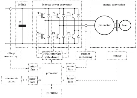
Figure 1. Outline of important devices of the considered drive system.
Manuscript received December 4, 2007.
II. REALIZED DRIVE SYSTEM
The investigated drive system is made up of many different hardware components [7-9]. The essential internal interaction between the supply dc-link, the dc to ac power converter, the motor, the sensor, the controllers and communicating tasks is schematical-ly depicted in Fig.1. The power conversion from the constant dc voltage link level to the ac voltage system at the motor is elementary performed by the PWM technology. The motor construction itself is built up for a mechanical load torque of approxi-mately 1.35 Nm. The rotating shaft is assisted with a speed sensor which measures the actual position. Depending on the control mode, an encoder or Hall-sensor is used. The communication purposes as well as main current and speed control algorithm are implemented in the processor.
III. HIGHER HARMONIC AIR-GAP WAVE BASED
PERMANENT MAGNET MOTOR DESIGN
The moving rotor with attached permanent magnets is almost characterized by its even number of involved magnetic poles, whereas the fixed novel stator winding design comprises the same pole number by means of higher space harmonics [10]. Both, stator and rotor designs are unskewed.
A. Design of the permanent magnet rotor
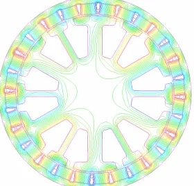
[image:2.595.99.239.455.589.2]Obviously a number of p 14= magnetic pole pairs are generated along the circumferential air gap direction. Favorably, the high pole number allows a very thin yoke construction.
Figure 2. Constant magnetic vector potential lines at no-load for the range ±0.002 Vs/m.
0,0 0,1 0,2 0,3 0,4 0,5 0,6 0,7 0,8 0,9 1,0
0 7 14 21 28 35 42 49 56 63 70
ra
dial air
ga
p
flu
x d
e
nsi
ty [T]
The invoked distribution of the magnetic field due to permanent magnet excitation is shown in Fig.2. The series space expansion of the radial flux density component Br( )ϕ along the circumferential air gap distance in accordance to
( )
r k k
k 0 ˆ
B B sin k
2
∞
=
ϕ
⎛ ⎞⎟
⎜
ϕ = ⎜⎜⎝ ⋅ + α ⎟⎟⎠ π
∑
(1)yields several harmonic coefficients ˆBk, k∈» with some distinct contributions, as it is obvious from Fig.3. The fourteenth component ˆB14 =0.91T in the no-load spectrum acts thereby as the fundamental air-gap wave of the drive.
B. Innovative stator design invoking higher harmonics
In order to generate the same number of p 14= rotor pole pairs, a fourteenth harmonic wave in the circumferential air gap flux density distribution has to be generated from the stator current excitation. This is advantageously done by the established alternating thin and thick tooth structure along the circumferential air gap.
The numerically calculated distribution of the magnetic field due to the stator current excitation only is shown in Fig.4. From the series expansion (1), the harmonic components ˆBk, k∈» of the wide spectrum in Fig.5 are obtained.
[image:2.595.355.499.456.588.2]There exists a lot of ordinal numbers with even different magnitudes. However, only the invoked fourteenth component with ˆB14 =0.045 T can inter-act with the rotor part in order to generate a constant mechanical average torque.
Figure 4. Constant magnetic vector potential lines in case of stator current injection for the range ±0.002 Vs/m.
0,0 0,1 0,2 0,3 0,4 0,5 0,6 0,7 0,8 0,9 1,0
0 7 14 21 28 35 42 49 56 63 70
ra
dial air
ga
p
flu
x d
e
nsi
[image:2.595.321.540.626.760.2] [image:2.595.56.273.626.761.2]IV. VECTOR CONTROLLED HIGHER HARMONIC
AIRGAP-WAVE BASED PERMANENT MAGNET MOTOR
The vector control mode operates the permanent magnet motor like a current source inverter driven machine applying a continuous current modulation [11-13]. Therefore, a very precise knowledge of the rotor position is necessary. This could be managed by applying an encoder on the rotating shaft. The vector control software is adapted to the hardware system which is schematically depicted in Fig.1.
A. Mathematical motor model
The practical realization of the control structure is fortunately done within the rotor fixed (d, q) refer-ence system, because the electrical stator quantities can there be seen to be constant within the steady operational state [14,15]. The stator voltage and flux linkage space vectors are therefore formulated in the (d, q) rotor reference frame as
( ) ( ) Sdq( ) ( )
Sdq S Sdq Sdq
d
u r i j
d
ψ τ
τ = τ + + ω τ ψ
τ
, (2)
( ) ( )
Sdq l iS Sdq Mdq
ψ τ = τ + ψ
, (3)
whereby rS denotes the normalized stator resistan-ce and ω τ( ) stands for the mechanical speed of the shaft. Thereby, the relation (3) covers only weak-saturable isotropic motor designs.
The inclusion of some basic identities for the permanent magnet flux space vector in the (d, q) system, namely
Mdq
d
0
dτψ = , ψMdq = ψ +M j0 , (4)
reduces the system (2), (3) to the set of equations
( ) ( ) ( ) ( )
Sd S Sd S Sd S Sq d
u r i l i l i
d
τ = τ + τ − ω τ
τ , (5)
( ) ( ) ( ) ( )
Sq S Sq S Sq S Sd M
d
u r i l i l i
d
τ = τ + τ + ω τ + ωψ
τ . (6)
Unfortunately, both equations (5), (6) are always directly coupled without the exception of standstill at ω =0. That fact is very unsuitable in particular for the design of the current controller. Thus, with regard to the used vector control topology, a more favorable rewritten form of (5), (6) as
( ) ( ) ( )
( ) ( )
d Sd S Sq
S Sd S Sd
u u l i
d
r i l i
d
τ = τ + ω τ =
= τ + τ
τ
, (7)
( ) ( ) ( )
( ) ( )
q Sq S Sd M
S Sq S Sq
u u l i
d
r i l i
d
τ = τ − ω τ − ωψ =
= τ + τ
τ
, (8)
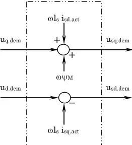
is commonly introduced. The decoupled structure (7), (8) introduces in Fig.6 fortunately both fictive
voltages ud( )τ , uq( )τ in order to adjust the
contr-oller of both axes independently from each other.
B. Simplified block diagram of the closed-loop vector control
The control schema in accordance to (7), (8) is realized in Fig.7 separately with regard to the d- and q- axis notation as a two-step overlaid cascade structure.
The outer speed cascade allows adjusting a pre-set speed value ndef, after getting smoothed by a
PT1-element. The output of the PI speed controller is also smoothed by a PT1-element and restricted by the thermal I2t-protection in order to avoid thermal
damages. The PI speed controller has a moderate sampling rate and determines the demanded q-current component. The drive is operated with a de-fault zero d-current component in order to achieve maximal torque output.
The actual measured electrical phase currents are transformed to the rotor fixed (d, q) reference syst-em and continuously compared to the dsyst-emanded d and q current components at the innermost current cascade structure. With regard to the d- and q-axis separation, the generated PI-current controller output voltages ud( )τ , uq( )τ are almost seen as
fictive quantities in Fig.7, from which the coup-ling-circuit given in Fig.6 calculates the real de-manded stator voltage components uSd( )τ , uSq( )τ
afterwards. The PI current controller is processed by a sampling rate of 8 kHz.
After transformation of the demanded stator voltage space vector into the (α β, ) stator coordinate
system, the power converter hardware generates the according voltages by using the PWM technique.
ud,dem
uq,dem usq,dem
usd,dem
ωls isd,act
ωls isq,act
[image:3.595.364.495.535.679.2]ωψM
I2T monitoring id,act nact
nmeas
PI-d current cont. ud,dem
imeas
γmeas PT1 smoothing
PT1 smoothing PI speed controller
ndem iq,dem
ndef
PI-q current controller uq,dem
iq,act
D conversion
uconverter usd,dem
de-coupl
-ing
d,q
a, b, c
a, b, c d,q id,dem
id,dem=0
PT1 smoothing
PT1 smoothing
id,act iq,act
[image:4.595.60.537.54.248.2]usq,dem
Figure 7. Outline of important devices of the vector controlled permanent magnet motor.
C. Electrical current shape and harmonic spectrum
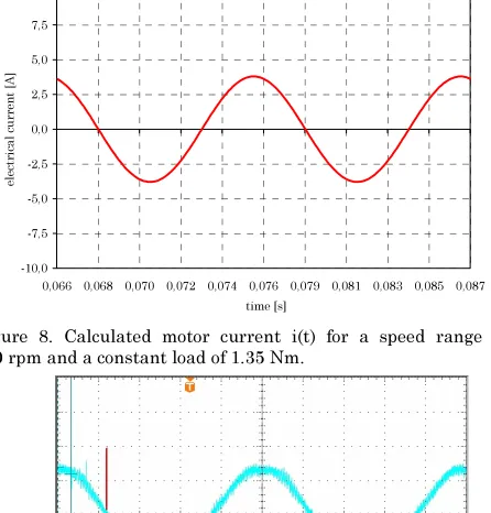
The vector control operation within the quasi-steady operational state at rated-load condition and a default speed value of 400 rpm enforces the time dependent current shape depicted in Fig.8 within the numerical calculation. A direct comparison with the measured course in Fig.9 in real-time conditions shows a very good agreement and confirms the assumptions and simplifications within the numeri-cal analysis procedure. The series expansion
( ) k
(
k)
k 1 ˆ
i t ∞ I sin 2 kf t
=
=
∑
π ⋅ + β (9)of the calculated electrical current from Fig.8 leads the harmonic components ˆIk, k∈». It is obvious
from the spectrum in Fig.10, that only the desired fundamental component ˆI1 =3.75A at 93.3 Hz is governing the total spectrum. The vector control in conjunction with the special motor obviously avoids additional harmonic components and restricts therefore unexpected thermal heating due to time-harmonic currents.
D. Mechanical torque shape and harmonic spectrum
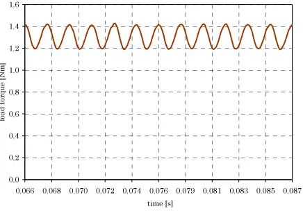
The numerical calculated time-dependent mech-anical torque m(t) is depicted in Fig.11. It results from the series expansion in time
( ) k
(
k)
k 0
ˆ
m t ∞ M sin 2 kf t
=
=
∑
π ⋅ + λ (10)that there exists within the harmonic components
k ˆ
M , k∈»0 almost the desired constant contrib.ut-ion of Mˆ0 =1.3Nm. By taking a closer look to the
calculated mechanical torque in Fig.12, a very dist-inct undesired harmonic component Mˆ6 =0.1Nm known as load pulsation moment exists even in
-10,0 -7,5 -5,0 -2,5 0,0 2,5 5,0 7,5 10,0
0,066 0,068 0,070 0,072 0,074 0,076 0,079 0,081 0,083 0,085 0,087 time [s]
el
ect
ri
cal cu
rrent
[A
[image:4.595.318.541.284.517.2]]
Figure 8. Calculated motor current i(t) for a speed range of 400 rpm and a constant load of 1.35 Nm.
Figure 9. Measured motor current i(t) for a speed range of
400 rpm and a constant load of 1.35 Nm. One division
corresponds to 2 ms in the abscissa and 2.5 A in the ordinate.
0,0 0,5 1,0 1,5 2,0 2,5 3,0 3,5 4,0
load cu
rren
t [A
[image:4.595.321.539.617.767.2]0,0 0,2 0,4 0,6 0,8 1,0 1,2 1,4 1,6
0,066 0,068 0,070 0,072 0,074 0,076 0,079 0,081 0,083 0,085 0,087 time [s]
lo
ad
to
rque
[N
m
[image:5.595.62.280.53.205.2]]
Figure 11. Calculated shaft torque m(t) for a speed range of 400 rpm and a constant load of 1.35 Nm.
0,0 0,2 0,4 0,6 0,8 1,0 1,2 1,4 1,6
0 200 400 600 800 1000 1200 1400 1600 1800 2000 frequency [Hz]
lo
ad
to
rque
[N
m]
Figure 12. Fourier coefficients Mˆk of the shaft torque for a speed
range of 400 rpm and a constant load of 1.35 Nm.
V. BRUSHLESS DCCONTROLLED HIGHER
HARMONIC AIR-GAP WAVE BASED PERMANENT
MAGNET MOTOR
The brushless DC magnet motor is operated with a space current distribution which does not rotate smoothly but remains fixed in distinct positions within sixty electrical degrees, and then jumps sud-denly to a position sixty electrical degrees ahead [16]. The brushless DC mode is also known as an electronically commutated motor operation. The current has to be commutated electronically bet-ween different phases controlled by diverse switch-ing semiconductors [17,18]. This is possible due to three Hall sensors which provide the necessary six electrical commutation informations during the rotor shaft movement. The current magnitude is kept to a required value and the current flows only through two of the three phases coevally.
The generated average mechanical torque remains always constant within the sixty degree electrical periods. The brushless DC control algorithm is set up at the hardware system explained in Fig.1.
A. Mathematical motor model
The machine equations in terms of according stator space vector notation is written in a stator fixed reference frame as
( ) ( ) S ( )
S S S
d
u r i
d
αβ
αβ αβ
ψ τ τ = τ +
τ
. (11)
The introduced stator flux space vector in (11) is fortunately written in case of weak-saturable isotropic inductances as
( ) ( ) Sαβ l iS Sαβ Mαβ ψ τ = τ + ψ
, (12)
whereby a rotor flux space vector of constant magnitude is assumed. The governing relation for the brushless DC feature is derived from (11),(12) as
( ) ( ) ( )
S S S S d S M
u r i l i j
d
αβ τ = αβ τ + αβ τ + ωψ αβ
τ
, (13)
whereby any transformation into a rotor fixed (d, q) reference system is avoided.
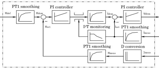
B. Simplified block diagram of the closed-loop brushless DC control
The control is realized with the aid of an outer speed as well an innermost current control cascade.
The imported Hall sensor signals, denoted after the interface with γmeas, are transformed to a contin-uous actual speed value with the aid of a D-element. Due to the low number of six Hall sensors, only very rough speed detection is feasible. The smoothed signal by a PT1 is denoted as nact. The actual speed nact is compared with the demanded speed ndem. The difference is in Fig.13 applied to the moderate PI speed controller which delivers the required motor current magnitude. This value is further limited by the thermal I2T protection, which takes implicit use of the actual measured motor current iact.
[image:5.595.64.281.235.385.2]PT1 smoothing PI controller
PT1 smoothing
D conversion I2T monitoring
ndem
iact
idem
ndef
nact
nmeas
PI controller
udem
imeas
γmeas
[image:6.595.132.466.47.191.2]PT1 smoothing
Figure 13. Simplified block diagram of the closed-loop speed and current control.
C. Time dependent current shape and harmonic spectrum
The influence of the electrical current commutat-ion from one phase to the other can be clearly seen in the calculated time-dependent course of Fig.14 for rated-load and the speed of 400 rpm. The measured quantity is given in Fig.15. Direct com-parison of calculated with measured courses shows a very good concordance. The implemented numeri-cal analysis is also very suitable to predict even higher harmonics in the motor current. The complete current spectrum (9) contains the funda-mental component ˆI1 =3.84A at 93.3 Hz. Moreover, some very distinct peaks within the spectrum could be observed. Several invoked higher harmonics such as ˆI5 =0.81A at 466.6 Hz, ˆI7 =0.62A at 653.3 Hz,
11
ˆI =0.31A at 1026.3 Hz and ˆI13=0.21A at 1212.9 Hz are causing negative effects, such as un-desired thermal heating.
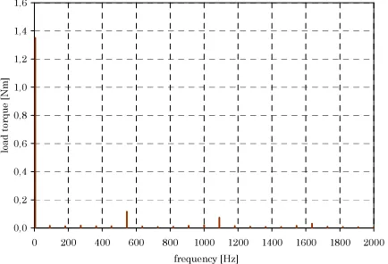
D. Time dependent torque shape and harmonic spectrum
The numerical calculated time-dependent mech-anical torque m(t) is depicted in Fig.17 for rated-load and a speed value of 400 rpm. It results from the series expansion (10) that there exists within the harmonic components Mˆk, k∈»0 almost the desired constant contribution of Mˆ0 =1.36Nm. The
known undesired torque fluctuations within Fig.17 can be seen more clearly in the harmonic spectrum depicted in Fig.18. Both distinct higher components are found to be Mˆ6 =0.12Nm at 559.8 Hz and
12 ˆ
M =0.09Nm at 1119.6 Hz. Other contributions to
the torque ripple are obviously suppressed. The occurring undesired load tip effects are well known to be responsible for eventually undesired noise emission.
-6,0 -4,5 -3,0 -1,5 0,0 1,5 3,0 4,5 6,0
0,057 0,059 0,061 0,063 0,065 0,067 0,070 0,072 0,074 0,076 0,078 time [s]
lo
ad curre
nt
[image:6.595.322.541.219.369.2][A]
Figure 14. Calculated motor current i(t) for a speed range of 400 rpm and a constant load of 1.35 Nm.
Figure 15. Measured motor current i(t) for a speed range of
400 rpm and a constant load of 1.35 Nm. One division
corresponds to 2 ms in the abscissa and 1.5 A in the ordinate.
0,0 0,5 1,0 1,5 2,0 2,5 3,0 3,5 4,0
0 200 400 600 800 1000 1200 1400 1600 1800 2000 frequency [Hz]
lo
ad curre
nt
[A]
[image:6.595.339.533.395.529.2] [image:6.595.321.539.571.719.2]0,0 0,2 0,4 0,6 0,8 1,0 1,2 1,4 1,6
0,057 0,059 0,061 0,063 0,065 0,067 0,070 0,072 0,074 0,076 0,078 time [s]
load t
orqu
e
[N
[image:7.595.62.280.54.205.2]m]
Figure 17. Calculated shaft torque m(t) for a speed range of 400 rpm and a constant load of 1.35 Nm.
0,0 0,2 0,4 0,6 0,8 1,0 1,2 1,4 1,6
0 200 400 600 800 1000 1200 1400 1600 1800 2000 frequency [Hz]
lo
ad
to
rque
[N
m]
Figure 18. Fourier coefficients Mˆk of the shaft torque for a speed range of 400 rpm and a constant load of 1.35 Nm.
VI. APPLICATION AND COMPARISON OF BOTH
CONTROL METHODS
In case of the well-balanced motor construction and a diligent sensor adjustment, the mostly un-desired torque fluctuation of the unskewed motor design still exist within the vector and brushless DC operational mode. In case of some technical applic-ations, this disadvantage could be accepted; other-wise the rotor has to be skewed. However, for many circumstances, the easy unskewed motor construct-ion and the much cheaper brushless DC control mode in conjunction with the higher harmonic air-gap wave based motor design is often favorized. Unfortunately, additional copper losses and varying iron losses are still reducing the thermal torque speed characteristic. In order to overcome those circumstances within certain ranges, the complex vector mode is commonly preferred.
VII. CONCLUSION
The novel axially unskewed higher harmonic air-gap wave based permanent magnet motor technolo-gy has been analyzed with regard to the closed-loop vector as well as brushless DC control method.
The main focus is thereby given to the verification of previously unknown and almost undesired effects, which could significantly worsen the quality of the complete drive system. The vector control method enforces only one distinct fundamental component in the electrical current consumption, whereas the brushless DC control causes a wide harmonic cur-rent spectrum. Undesired load pulsation effects of the unskewed motor could be slightly reduced by preferring the vector control method.
The applied transient electromagnetic-mechanical finite element calculation method with additionally coupled external circuits in the time-domain allows the inclusion of basic control features and is therefore very suitable for a straightforward and accurate analysis of the complete converter fed speed-variable drive system in advance.
REFERENCES
[1] J.S. Salon, Finite element analysis of electrical machines, Cambridge University Press: Cambridge, 1996.
[2] M.J. DeBortoli, Extensions to the finite element method for the electromechanical analysis of electrical machines, PhD Thesis, Rensselaer Polytechnic Institute, New York, 1992. [3] J.P.A. Bastos and N. Sadowski, Electromagnetic modeling by
finite element method, Marcel Dekker: New York/Basel, 2003. [4]P.F. Brosch, Moderne Stromrichterantriebe, Vogel: Würzburg,
1989.
[5] W.Leonhard, Control of electrical drives, Springer: Berlin, 2001.
[6] G.K. Dubey, Fundamentals of electrical drives, Alpha Science Int.: Pangbourne, 2001.
[7] K.B. Bimal, Power electronics and variable frequency drives: technology and applications, IEEE Press: New York, 1996. [8] K. Heumann, Principles of power electronics. Berlin: Springer
Verlag, 1986.
[9] G. Seguier and G. Labrique, Power electronic converters: dc to ac conversion. Berlin: Springer Verlag, 1989.
[10]T. Bödefeld and H. Sequenz, Elektrische Maschinen,
Springer: Wien/New York, 1942.
[11]P. Vas, Vector control of AC machines, Oxford University Press: Oxford, 1990.
[12]K.G. Bush, Regelbare Elektroantriebe: Antriebsmethoden, Betriebssicherheit, Instandhaltung, Verlag Pflaum: München, 1998.
[13]W. Nowotny and T.A. Lipo, Vector control and dynamics of AC drives, Clarendon Press: Oxford, 2000.
[14]P. Vas, Electrical machines and drives: A space-vector theory approach, Clarendon Press: Oxford, 1996.
[15]P. Vas, Parameter estimation, condition monitoring, and diagnosis of electrical machines, Clarendon Press: Oxford, 1993.
[16]R. Lehmann, Technik der bürstenlosen Servoantriebe,
Elektronik, Vol. 21, 1989.
[17]T.J.E. Miller, Brushless permanent magnet and reluctance motor drives, Clarendon Press: Clarendon, 1989.
[image:7.595.64.281.234.382.2]