Jet heat transfer in the vicinity of a
rotating grinding wheel
T S O’Donovan
, D B Murray,andA A Torrance
Department of Mechanical and Manufacturing Engineering, University of Dublin, Trinity College, Dublin, Ireland
The manuscript was received on 24 October 2005 and was accepted after revision for publication on 28 February 2006.
DOI: 10.1243/09544062JMES215
Abstract: Impinging jets are known as a method of achieving high convective heat transfer coefficients. One potential application of impinging jet heat transfer is the air jet cooling of a grinding process. A grinding process generates heat that must be dissipated to avoid thermal damage. To date, this has been achieved using flood cooling with a traditional coolant such as an oil and water mixture; however, using a jet of air in its place has obvious environmental and economic benefits. For a range of grinding test configurations, results are presented of the convective heat transfer from the workpiece, along the notional plane of cut, and of the air flow velocity in a two-dimensional plane perpendicular to the workpiece. It has been shown that a boundary layer that develops around the rotating grinding wheel has the effect of displacing a peak in the distribution of the local heat transfer coefficient from the notional arc of cut. To effectively cool the grinding zone, therefore, it is necessary to penetrate this boundary layer and this can only be achieved when the jet velocity is substantially greater than the tangential velocity of the wheel.
Keywords: grinding, impinging jet, heat transfer, cooling
1 INTRODUCTION
Convective heat transfer due to an impinging air jet yields high local and area-averaged heat transfer coefficients. As a result, it has potential for the cool-ing of a grindcool-ing process. Grindcool-ing is a widely employed machining process used to achieve good geometrical form, dimensional accuracy, surface finish, and surface integrity. However, grinding gen-erates heat that must be dissipated, as high tempera-tures may damage the workpiece. High temperatempera-tures adversely affect process times because the depth of cut and feed rates cannot be increased without com-promising surface quality. Thermal damage can manifest itself in many ways. Most notably, it results in the softening of the ground surface which can cause rehardening and embrittlement. In addition, thermal expansion can compromise the geometrical
accuracy and may leave residual tensile stresses in the workpiece. Excessive temperatures may also have the adverse effect of inducing accelerated wear of the grinding wheel. The current research focuses on the use of an air jet as an alternative to tra-ditional methods, such as flood cooling, with a mix-ture of oil and water to cool a grinding process. It is expected that an air jet can achieve the necessary workpiece cooling while reducing the machining cost and the environmental impact of grinding processes.
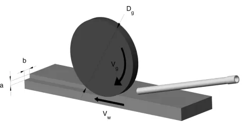
The geometric parameters of a grinding process are depicted in Fig. 1. The grinding wheel is shown to rotate in a clockwise direction with a tangential velocityVg. The workpiece is fed with a velocityVw in the direction of the wheel. This configuration is termed down grinding. Up grinding is the case where the wheel rotates in the opposite direction to the movement of the workpiece. The depth of cut,
a, shown exaggerated in the diagram, is typically 5mm during conventional grinding. The workpiece exerts a tangential force,Ft, on the grinding wheel. In this configuration, the jet flows in the direction of the
Corresponding author: Department of Mechanical and
workpiece with velocity Vj. The power generated during the grinding process is dissipated as heat in the grinding zone, where this heat flux is defined as
q00
total¼
FtVg
b ffiffiffiffiffiffiffiffiffiaDg
p (1)
With conventional flood cooling, this heat is dissi-pated in four ways: (a) conduction to the grinding wheel grains, (b) conduction into the workpiece, (c) convection to the cutting fluid, and (d) with the removal of the cutting chip. An energy balance, pre-sented in equation (2), defines the modes of heat dis-sipation. Typically, the heat transferred to the chip is small when compared with the overall heat gener-ated and is neglected in studies by Lavine and Jen [1], for example
qtotal¼qworkpieceþqwheelþqfluidþqchip (2)
During grinding, heat is generated by the grains of the wheel cutting the workpiece as they pass at high speeds in the grinding zone. According to Roweet al.
[2], individual grains are responsible for localized and intense heat generation, resulting in short duration spike temperatures at the workpiece sur-face. However, the total effect of a large number of grains cutting the relatively slow moving workpiece surface can be considered to be a continuous band source of heat passing over the workpiece. The temperature due to this band source is a background temperature that occurs for a substantial period of time. Spike temperatures are not of consequence for thermal damage, because thermal damage such as re-austenitization requires time to occur.
An investigation by Ebbrellet al.[3] recognized the effect of ambient air entrainment by the spinning grinding wheel. It was determined that the hydro-dynamic boundary layer that forms. around the spin-ning grinding wheel produces a back flow when the grinding wheel boundary layer comes into close proximity with the workpiece. This back flow can inhibit the cutting fluid from reaching the grinding
zone. Ebbrellet al.[3] also presented various nozzle configurations to overcome the effect of the bound-ary layer.
Roweet al.[2] conducted a numerical and exper-imental investigation of energy partitioning in a grinding process for two different grinding wheel materials, where the partition ratio is defined as the ratio of the heat transferred to the workpiece to the total heat generated
Rpartition¼
qworkpiece
qtotal
(3)
A grain contact model was used to predict the par-tition ratio by assuming that the heat transported by the cutting fluid and the chip was negligible. The model also required a value of the effective thermal conductivity of the grain. This value was arrived at when both the model and the experimental tempera-tures correlated.
A theoretical model for heat transfer during grind-ing was developed by Lavine and Jen [1]. This model assumed that the heat flux to the fluid from the work-piece was uniform and that the fluid moved at the same velocity as the tangential velocity of the wheel. Therefore, the fluid was modelled as a solid, with a uniform heat flux at its surface. It was also shown that the convective heat transfer to the fluid from the grinding wheel was small, typically 0.4 per cent of the heat transfer to the grinding wheel. A later model by Jen and Lavine [4] addressed some of the assumptions made by the original model, par-ticularly by modifying the assumption of uniform heat flux to the grinding wheel grains, fluid, and workpiece. In an investigation by Jen and Lavine [5], a model was developed which predicted the effect on workpiece temperature of the occurrence of film boiling. In addition, in an investigation by Lavine [6], an exact solution for the surface tempera-ture in a grinding process was developed. In the pre-vious models, it had been assumed that the heat was generated at the wear flats. This is known to be untrue, as much of the heat is generated at shear planes because of plastic deformation.
In all of the earlier works, the cutting fluid was a liquid, typically an oil and water mixture. The func-tion of the cutting fluid is primarily to reduce the amount of heat generated by lubricating the process rather than transporting heat away by convection. The present research is concerned with the cooling of a grinding process with an impinging air jet, a procedure that has received little attention until now. Instead of targeting the heat generation in the grinding zone, this method reduces the high temp-eratures by substantially increasing the convective cooling.
[image:2.595.37.278.88.213.2]High-speed air jet cooling of a grinding process has been investigated by Babic et al. [7]. This investi-gation showed that a high-speed jet can slightly reduce the heat generated in the grinding zone by reducing the tangential force. However, the main mechanism for the reduction in temperature in the grinding zone was considered to be enhanced-convective heat transfer to the impinging air jet. In a subsequent investigation by Babic et al. [8], a small quantity of water was injected into the air flow before the nozzle, which generated a high-speed jet mist. The use of this jet mist in a grinding process was shown to further reduce the tangential force and to increase the convective cooling. To date, convective heat transfer coefficients have not been quantified in the available literature. In the pre-sent study, experiments have been performed that measure the convective heat transfer coefficient to the impinging jet flow used by Babicet al.[7].
The current research is concerned with the funda-mental heat transfer mechanisms that occur in an impinging jet flow and with the application of air jet cooling to a grinding process. Convective heat transfer distributions along the workpiece are reported together with the associated flow fields. The convective heat transfer mechanisms that occur in an air-cooled grinding process are investi-gated with a view for determining an optimal jet configuration.
2 EXPERIMENTAL SETUP
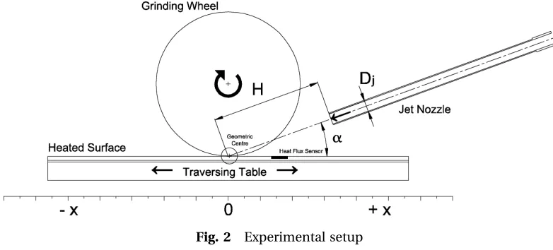
A schematic of the experimental rig is presented in Fig. 2. This setup is designed to approximate a grind-ing process. The workpiece is represented by a composite plate, measuring 425 mm550 mm, that consists of three main layers mounted on a car-riage. The top surface is a 5 mm thick copper plate. A silicon rubber heater mat,1.1 mm thick, is fixed to
the underside of the copper plate with a thin layer of adhesive. It has a power rating of 15 kW/m2 and a voltage rating of 230 V. The voltage is varied using a variable transformer that controls the heat supplied to the copper plate. A thick layer of insulation pre-vents the heat loss from the heating element rather than through the copper. The plate assembly is such that it approximates a uniform wall tempera-ture boundary condition, operating typically at a surface temperature of 608C.
An RdF Micro-Foilw
heat flux sensor is flush mounted on the heated surface to measure the surface heat flux. The heated plate is mounted on a carriage that travels on a track, thus allowing the sensor to be placed in any location along the notional cutting plane. This sensor contains a differential thermopile that measures the temperatures above and below the known thermal barrier. The heat flux through the sensor is, therefore, defined by equation (4).
q00¼k
s DT
d (4)
where ks is the thermal conductivity of the barrier (kapton) and DT is the temperature difference across the thickness (d) of the barrier. A single pole thermocouple is also embedded in this sensor to measure the temperature locally.
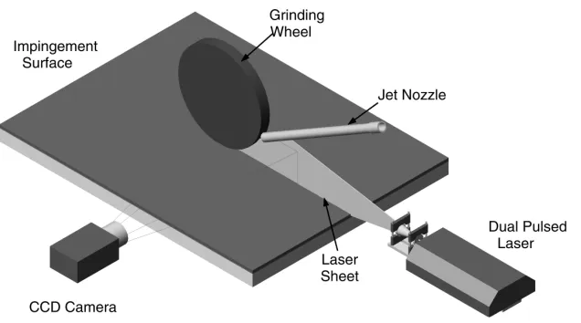
The flow velocity field has been measured and mapped using digital particle image velocimetry (DPIV), as illustrated in Fig. 3. The DPIV system con-sists of a 15 mJ Nd:YAG double pulse laser and a double shutter PCO Sensicam. The resolution of the camera is 12801024 pixels and the minimum time between frames is 200 ns. Glycerine particles (5mm diameter) were used to seed the main flow and the entrained air of the jet.
A grinding wheel is suspended0.5 mm above the surface and is driven with an AC Motor. Its rotational
[image:3.595.110.501.599.776.2]speed is controlled using a frequency inverter. Con-tact is not made between the grinding wheel and the surface; this is to ensure that the sensors are not damaged by the rotating wheel. The grinding wheel is an aluminium oxide wheel of diameter 180 mm and thickness 19 mm.
Two nozzle types are used in this investigation. The first consists of a brass pipe of 13.5 mm internal diameter. The pipe is 20 diameters long and a 458 chamfer is machined at the nozzle lip to create a sharp edge to minimize entrainment. The second has a diameter of 2.6 mm. This nozzle is used to create a high-speed jet that can approach sonic vel-ocities and has been used for impingement jet cool-ing of an actual grindcool-ing process, as described by Babicet al. [8]. The nozzle is clamped on a carriage in an arrangement that allows its height above the impingement surface and its angle of impingement to be varied. The height of the nozzle can be varied from 0.5 to 10 nozzle diameters above the impinge-ment surface and
Q2 the jet can be set at oblique angles ranging from 158, in 158 increments, up to the normal angle of impingement (908).
Air is supplied to the jet nozzle by a compressor. An Alicat Scientific Inc. Precision Gas Flow Meter is installed on the compressed air line to monitor both the air volume flowrate and the temperature. It is important that the jet exit temperature is main-tained within 0.58C of the ambient air temperature. To this end, a heat exchanger is installed on the air line. The heat exchanger consists of a controlled temperature water bath in which a series of copper coils are placed. The air flows through the copper coils to increase the jet exit temperature to the required setting.
A number of differences exist between this test setup and the typical setup for a grinding process, as illustrated in Fig. 1. First, the surface being ground is represented as a flat surface in the heat
transfer testing. This approximation is not con-sidered to be significant for conventional grinding as the depth of cut is in the region of 0.005 mm; how-ever, for creep feed grinding, the depth of the cut varies up to 20 mm. Secondly, it was necessary to mount the grinding wheel slightly above (0.5 mm) the heated surface to protect the heat transfer sensor that is flush mounted on the heated surface. This contrasts with the situation in an actual grinding process where the wheel is in contact with the surface. The setup used is similar to that used by Ebbrellet al.[3] who investigated the effect of such a gap on the pressure distribution along the grinding plane and on the back flow resulting from the grind-ing wheel boundary layer. The gap was found to exert a significant influence on the flow characteristics, as the peak pressure varied from 250 to 50 Pa for a gap of 0.005 – 1.5 mm, respectively. It is important to rea-lize that the smallest gap of 0.005 mm investigated by Ebrell et al. [3] approximates the grinding process quite accurately as the contact area between the grinding wheel grits and the workpiece in the grind-ing zone is typically only a few per cent of the total grinding zone area. The consequence of the relatively large gap used in this study is a reduction in the mag-nitude of the back flow by allowing some flow under the grinding wheel surface.
[image:4.595.133.451.89.266.2](Tj) and the local surface temperature (Tsurf) is used to calculate the convective heat transfer coefficient. Thus, the heat transfer coefficient will tend to be underestimated in this study, as the calculation is based on a larger temperature difference than actu-ally exists locactu-ally. However, the location of peaks and troughs in the heat transfer distributions will not change significantly. Finally, the heated surface that represents the workpiece is stationary during experimental testing. In a grinding process, the work-piece would typically traverse under the grinding wheel with a velocity of 0.2 m/s. This velocity is small relative to both the air jet and the grinding wheel tangential velocities, and therefore, neglecting it will not have a significant influence on the results. Results are presented in the form of the local convective heat transfer coefficient as follows
h(x)¼ q€(x)
(Tsurf(x)Tj)
(5)
A complete calibration and uncertainty analysis for this experimental setup are presented by O’Donovan [9]. The uncertainty of the convective heat transfer coefficient is calculated to be +6 per cent, and the jet exit velocity can be set to an accu-racy of 5 per cent.
3 RESULTS
3.1 Rotating grinding wheel
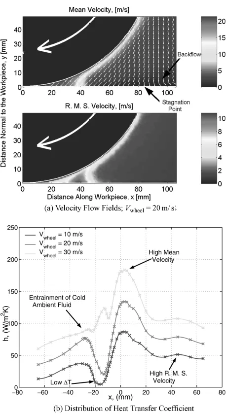
A rotating grinding wheel entrains air from the sur-roundings and induces a flow pattern that influences the heat dissipation in grinding. In an experimental investigation by Rowe et al. [2], back flow was reported for the air entrained by the grinding wheel. The air entrained by the wheel flows in the same direction as the wheel until it comes into close proximity with the surface or workpiece. As the air reaches the minimum gap between the wheel and the plate, some of the flow stagnates and then flows backwards away from the grinding zone. In the present study, this is confirmed by the PIV data presented in Fig. 4(a), where the wheel is rotat-ing with a tangential velocity of 20 m/s. The back flow magnitude is small and occurs far from the minimum gap, in this case, beyond the stagnation point at x85 mm. This is understandable as the relatively large gap between the wheel and the sur-face (0.5 mm) allows much of the entrained air to pass under the wheel.
Figure 4(b) presents heat transfer distributions because of the flow induced by the entrainment of ambient air by the rotating grinding wheel. The con-vective heat transfer coefficient is plotted along the
centre-line of the notional grinding plane. In this case, where there is no jet, the convective heat trans-fer coefficient is based on the temperature diftrans-ference between the surface and the ambient air as follows
h(x)¼ q€(x)
(Tsurf(x)Tamb)
(6)
From the right, a subtle peak occurs at a position of
x42 mm. This is due to a region of high turbulence intensity occurring in the wedge between the grind-ing wheel and the surface, as evident in Fig. 4(a). The main peak in heat transfer is because of the peak velocity at the minimum gap (x¼0). Measure-ments of the velocity flow field have not been acquired beyond this point (x,0) because of block-ing of the laser sheet by the grindblock-ing wheel. As the air Fig. 4 Fluid flow and heat transfer due to rotating
[image:5.595.325.554.87.507.2]moves beyond this point, however, it is thought that the heat transfer rate decreases because of the low temperature difference between the surface and the local fluid, leading to a minimum heat transfer. This could also be due to a local flow characteristic. As the gap between the wheel and the surface increases, again further fluid is entrained, increasing the heat transfer rate once more. Eventually, the heat transfer coefficient falls off as the local fluid vel-ocity decreases with the distance from the grinding wheel.
3.2 Low-speed air jet
In Figs 5 and 6, the fluid flow and the corresponding heat transfer distributions are presented for a jet
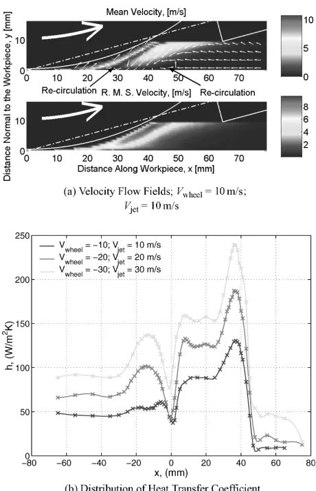
impinging on the notional grinding zone at angles of 308and 158, respectively. The distance of the jet exit from what would be the grinding zone (notional arc of cut) in a grinding process is the same for both configurations and is defined as the minimum gap possible for positioning the jet at an angle of 308. These heat transfer distributions differ somewhat from those in Fig. 4(b) because the largest peak is now due to the stagnation point of the jet flow and occurs at x¼30 and 35 mm for a¼308 and 158, respectively. From Figs 5(a) and 6(a), it is apparent that the jet flow is blocked by the spinning grinding wheel in both configurations; however, this is more severe for the larger angle. At 308, the peak in the heat transfer distribution that is attributed to the jet stagnation point is displaced by10 mm, from the expected location of 20 mm from the geometric centre for an unobstructed jet flow to 30 mm from the notional arc of cut in the grinding configuration. In the case where the jet impinges at an angle of 158, this displacement is less significant with the maxi-mum heat transfer occurring at 35 mm from the notional arc of cut, rather than the 30 mm expected
Fig. 5 Fluid flow and heat transfer due to jet cooling with rotating grinding wheel: a¼308 and
H¼101 mm
[image:6.595.40.273.306.722.2] [image:6.595.307.536.389.740.2]for an unobstructed jet. This peak also has a greater magnitude for the impingement angle of 158. This enhancement has also been attributed to the air jet flowing, unobstructed by the grinding wheel, to the grinding zone at this angle.
The r.m.s. velocity flow field has not changed sig-nificantly with the addition of the impinging air jet; the magnitude of the turbulence intensity remains high in the wedge made between the grinding wheel and the surface. The streamlines in the vel-ocity flow field also indicate that some of the air flow recirculates, and is entrained by the wheel, after it has been in contact with the heated surface. The recirculation zone is indicated by an arrow in Fig. 5(a) and occurs at 45 mm from the grinding zone. In general, recirculations in the flow have a negative effect on the heat transfer coefficient; how-ever, the magnitude of the velocity of the recirculat-ing air is small and therefore it does not significantly influence the distribution of the heat transfer coeffi-cient. Overall, the magnitude and distribution of the heat transfer coefficients are relatively unaffected by this low-speed impinging jet.
Figure 7 presents the results for a grinding wheel turning in the opposite direction to the impinging jet flow. It can be seen from Fig. 7(b) that this con-figuration does not have a favourable influence on the convective heat transfer coefficient in the grind-ing zone. Although the heat transfer distributions exhibit similar peaks to the previous distributions, they occur at different locations and have altered magnitudes. In particular, the convective heat transfer coefficient is a minimum at the notional grinding zone (x¼0). This local minimum has been attributed to the local flow stagnating at the location of the minimum gap and is associated with a large recirculation pattern in the fluid flow. Figure 7(a) shows that much of the air leaving the notional grinding zone is recirculated and re-enters the grinding zone. This has a negative effect on the heat transfer coefficient because the air entering this critical zone has an elevated temperature.
The maximum intensity of turbulence (9.2 per cent) is higher in this grinding configuration, but at a large distance from the surface. The peak turbu-lence intensity is measured along the stagnation zone that occurs between the two distinct flow regions corresponding to the wheel-induced flow and jet flow, respectively. The turbulence intensity close to the surface (6.6 per cent), where the influ-ence on heat transfer is greatest, remains compar-able with the case where both the jet and wheel velocities are in the same direction.
Although the heat transfer coefficient is high at other locations, this is an unfavourable configuration for cooling of a grinding process because of the local
minimum in convective heat transfer coefficient in the critical region of the arc of cut.
3.3 High-speed air jet
Heat transfer data were also acquired for a high-speed jet of diameter 2.6 mm directed towards the instrumented test plate. However, PIV data were not obtained because of a difficulty in seeding the high-speed jet flow. This jet has been used for cool-ing of an actual grindcool-ing process, as described by Babic et al.[8], and has proven to be a surprisingly effective cooling arrangement. Two different jet pos-itions were tested in this part of the heat transfer investigation and these are illustrated in Fig. 8. The first jet position tested is the same as used for the previous 158 test, namely, where the wheel rotates about a point directly above the geometric centre of the jet. The second position was chosen to coun-teract the effect of the wheel in blocking the jet flow; thus the jet was positioned at a minimum height above the plate but still at an angle of 158. Fig. 7 Fluid flow and heat transfer due to jet cooling of
[image:7.595.324.554.88.445.2]The distributions of heat transfer coefficient shown in Fig. 9 no longer exhibit the same number of local maxima and minima, as the high-speed of the jet has managed to penetrate the boundary layer flow around the grinding wheel. The predomi-nant peak still occurs at the stagnation point of the
jet (x25 mm) and the heat transfer distribution also exhibits a more subtle change in slope at the grinding zone (x¼0 mm). However, the most signifi-cant change to be noted is that the heat transfer is greatly enhanced over the entire grinding zone in comparison with the low-speed jets.
The first jet position considered is thought to be less favourable because the jet is effectively imping-ing on the wheel and not on the grindimping-ing surface. In a grinding process, cooling of the grinding wheel itself may well be an effective method of reducing the temperature in the grinding zone. In this investi-gation, however, direct convective cooling of the workpiece itself is under consideration. For this reason, the obliquely impinging jet was positioned so that the convective heat transfer from the work-piece would be maximized and thus the height of the jet was minimized. In this case, the jet impinge-ment position is not directed at the minimum gap but slightly to the right of it. Heat transfer coefficients for this jet setup have proven to be even more favour-able, although the peak heat transfer coefficient still does not occur close to the grinding zone. Despite this, the second jet setup shown in Fig. 8 has mana-ged to almost double the heat transfer coefficient in the grinding zone for the same flowrate of air.
High-speed air jets have been been applied to an actual grinding process by Babicet al.[8]. The maxi-mum workpiece temperatures were measured for various cooling methods and are shown in Table 1. In this case, the depth of cut was 10mm and the tan-gential velocity of the wheel was 28 m/s.
It has been shown that the air jets reduce the work-piece temperature, but not quite so much as a con-ventional cutting fluid. However, when a small volume of water is added to the air stream, the mist cooling becomes more effective than with a conven-tional coolant.
4 CONCLUSIONS
PIV data have been used to illustrate some of the flow characteristics that occur when an air jet impinges Fig. 8 Schematic of high-speed impinging jet setup
[image:8.595.37.278.70.210.2]Fig. 9 Wheel and high-speed impinging jet heat transfer distributions
Table 1 Grinding temperatures [8]
Cooling method
TWorkpiece
(8C)
No cooling 320
Water emulsion (5% HOCULT B60CB coolant oil)
12.6 mm diameter nozzle; speed¼2.9 m/s 218 Dry air jet
22.6 mm diameter nozzles; speedMach 1 268 Air and water mist
22.6 mm diameter nozzles; 1 g/s water; speedMach 1
[image:8.595.298.539.98.225.2] [image:8.595.41.271.348.738.2]on a flat plate with a rotating grinding wheel mounted above the surface, representative of the workpiece in a grinding process. From these data, the influence of the flow on heat transfer has been inferred. The two main differences between the experimental setup and an actual grinding process are the thermal boundary condition and the non-contact between the surface and the wheel. The sig-nificance of these approximations has been dis-cussed and it can be concluded that the convective heat transfer coefficient is probably underestimated as a result of these differences. However, it is likely that the peaks in the distributions occur in the same locations.
1. The rotating grinding wheel entrains a boundary layer that impinges on the grinding surface. The heat transfer to this induced flow has a convection coefficient comparable with that of an impinging air jet of similar velocity. In general, the boundary layer developed around the rotating grinding wheel has a negative effect on the cooling of a grinding process, as it prevents the jet flow from reaching the grinding zone. It also has the effect of moving the stagnation point, where the peak in heat transfer coefficient occurs, away from the grinding zone.
2. Depending on the grinding configuration, recircu-lations in the flow have been revealed. These have a negative effect on the heat transfer coefficient as the local surface to fluid temperature difference would be reduced.
3. Peaks in the heat transfer distributions have been successfully linked to regions of high fluid velocity and turbulence intensity. For the conditions investigated, the r.m.s. velocity or the turbulence intensity is a maximum in the wedge made between the grinding wheel and the grinding sur-face. It has also been established that an angle of impingement of 158 is preferable to 308 as the maximum peak in the heat transfer distributions occurs at this angle.
4. When a counterflow cooling configuration is tested, the heat transfer coefficient is usually a minimum at the arc of cut. This coefficient tends to zero for low velocities, suggesting the occur-rence of an instantaneous stagnation point in the flow. This indicates that a countercurrent con-figuration is not appropriate for the cooling of a grinding process.
5. It has been shown that a high-speed jet effectively penetrates the boundary layer flow around the grinding wheel, providing good cooling of the grinding zone.
6. Positioning of the high-speed jet has also been shown to be critical in enhancing the convective heat transfer. In general, the high-speed jet
provides more effective cooling than the low-speed jet; however, if the distance of the jet from the grinding zone is decreased, the heat transfer coefficient can be further increased by a factor of 2.
The cooling of a grinding process has many characteristics that are unique to the specific application.
Although this investigation has been predomi-nantly directed towards cooling of the grinding zone itself, it is worth noting that the area surround-ing the grindsurround-ing zone will be at a somewhat elevated temperature and more of the heat transfer coefficient distribution will be utilized in the overall cooling of a grinding process. It would also be of benefit if the impinging air jet was colder than the ambient air or workpiece. In this case, the precooling of the entire workpiece would also serve to reduce the tempera-ture in the grinding zone. Futempera-ture work should include an investigation of the effect on heat transfer of a difference in temperature between the ambient air and the jet air.
ACKNOWLEDGEMENT
This work was supported in part by Enterprise Ire-land under grant SC/2001/0071 and also by Science Foundation Ireland grant 04/BR/EO108.
REFERENCES
1 Lavine, A. S.andJen, T. C.Thermal aspects of grinding: heat transfer to workpiece, wheel and fluid.ASME J. Heat Trans., 1991,113, 296 – 303.
2 Rowe, W. B., Black, S. C. E., Mills, B., Morgan, M. N., andQi, H. S. Grinding temperatures and energy parti-tioning.Proc. Roy. Soc. Lond. A, 1997,453, 1083 – 1104. 3 Ebbrell, S., Woolley, N. H., Tridimas, Y. D.,
Allanson, D. R.,andRowe, W. B.The effects of cutting fluid application methods on the grinding process.Int. J. Mach. Tools Manuf., 2000,40, 209– 223.
4 Jen, T. C.andLavine, A. S.A variable heat flux model of heat transfer in grinding: model development. ASME J. Heat Trans., 1995,117, 473 – 478.
5 Jen, T. C.andLavine, A. S.A variable heat flux model of heat transfer in grinding with boiling. ASME J. Heat Trans., 1996,118, 463 – 470.
6 Lavine, A. S.An exact solution for surface temperature in down grinding. Int. J. Heat Mass Trans., 2000, 43, 4447 – 4456.
7 Babic, D. M., Murray, D. B.,andTorrance, A. A.Control of grinding temperature by high speed air jets.Proc. ITSS II Int. Therm. Sci. Semin., 399 – 406. Q3 8 Babic, D. M., Murray, D. B.,andTorrance, A. A.Mist jet
9 O’Donovan, T. S. Fluid flow and heat transfer of an impinging air jet.PhD Thesis, Department of Mechan-ical Engineering, University of Dublin, Trinity College, 2005.
APPENDIX
Notation
a depth of cut (m)
b grinding wheel thickness (m)
D diameter (m)
F force (N)
h convective heat transfer coefficient (W¼m2K)
H height of nozzle above impingement surface (m)
k thermal conductivity (W¼mK)
q rate of heat transfer (W)
q00 heat flux (W¼m2) R partition ratio
T temperature (K)
V velocity (m/s)
x horizontal coordinate a angle of impingement (8) d sensor thickness (m)
Subscripts
amb ambient g grinding wheel
j jet
s sensor
TO: CORRESPONDING AUTHOR
AUTHOR QUERIES - TO BE ANSWERED BY THE AUTHOR
The following queries have arisen during the typesetting of your manuscript. Please answer these queries by marking the required corrections at the appropriate point in the text.
Q1 Please provide unit.
Q2 Please check the sense of the sentence “the height of …….”.

![Table 1Grinding temperatures [8]](https://thumb-us.123doks.com/thumbv2/123dok_us/1359766.668595/8.595.41.271.348.738/table-grinding-temperatures.webp)
