hybrid-simulation modeling framework
July 17, 2019 Dédé Reichart
Research conducted by: P.A. (Dédé) Reichart S1356453 [email protected]
Commissioned by:
ing. M. R. (Maarten) Visser MSEng
Witteveen+Bos University supervisors:
dr. ir. F. (Farid) Vahdatikhaki Construction Management & Engineering
University of Twente
dr. ir. L.L. (Léon) olde Scholtenhuis Construction Management & Engineering
University of Twente
prof. dr. ir. A.G. (André) Dorée Construction Management & Engineering
This paper is the result of conducted scientific research to complete the master Construction Management & Engineering at the University of Twente. After being inspired by new digital and technological developments in the construction industry and at the same time being a bit disappointed by the massive gap between research and practice, I started to think about a small and renewing contribution for both. After becoming acquainted with new digital developments and BIM related subjects, improving planning and scheduling through simulations was a tangible domain for my research.
Achieving concurrent planning for construction projects through a
hybrid-simulation modeling framework
P.A. Reichart1,2
1 University of Twente, Enschede, the Netherlands 2 Witteveen+Bos, Deventer, the Netherlands
Abstract
Conventional sequential planning approaches could overlook a large number of feasible execution scenarios throughout the planning process. In such planning, various decisions (e.g. activity-sequencing, resource allocation) are taken in consecutive steps to gradually reduce the solution space. This could result in suboptimal schedules in terms of duration and cost. Therefore, this paper proposes a framework for simulation-based concurrent planning that can simultaneously integrate multiple decision steps in planning procedures. A hybrid-simulation modeling approach is adopted to integrate discrete-event and agent-based simulations. In specific, the framework integrates several decision variables regarding sequencing, site lay-out planning, resource allocation and risk management. The framework is applied to an existing cut & cover operation case study to explore its feasibility. Experts’ validation showed that much detailed and accurate information is generated in a short amount of time. This demonstrates that the proposed hybrid-simulation approach can facilitate concurrent planning for construction projects while obtaining significant efficiency benefits with respect to conventional planning approaches.
I. Introduction
Construction projects are continuously growing in physical size, complexity and budget [1, 2] This increases the pressure to deliver the projects on time and within budget [3]. Project planning (e.g. generally defining the project goals, constraints, construction method, construction sequence and risk-strategy) and subsequently project scheduling (i.e. involving specific dates, durations and tasks) play a critical role for achieving this objective [1, 4]. However, planning construction projects is known to be very complex due to environmental, technical and financial challenges [3, 5, 6].
When planning complex projects, planners have several decision variables (e.g. start location, storage location of the materials and resources, amount of equipment and workforce deployed) which impact the project’s duration and corresponding costs significantly [6]. To deal with the complexity of projects and cognitive constraints of a planner, these planning decisions are conventionally taken in several consecutive steps (e.g. sequencing activities, site lay-out planning, resource allocation). This reduces the solution space of possible execution scenarios for eventually the schedule [7, 8]. The decision made in each of these steps can support development of scenarios but also exclude others. Making decisions stepwise throughout the planning process limits the number of feasible execution scenarios for the construction operation. For example, defining the start location of the construction operation puts a constraint on sequence options (directions) or possible site lay-outs and locations. These limitations could eventually result in suboptimal execution schedules regarding time and costs, due to overlooked and unconsidered (optimal) scenarios. Moreover, these approaches are extremely time consuming [8, 9] and require an extensive amount of knowledge and planning expertise [3]. Other issues, such as lack of co-operation between the planners’ logic and on-site operations [10], insufficient involvement of uncertainties (in activity duration and occurring risks) during decision making [11, 12] demand for a more efficient and integral planning approach. Hence, it can be concluded that conventional sequential planning approaches are not sufficient to incorporate all necessary project details and complexities [2].
Concurrent planning methods (i.e. parallel procedures), which involve multiple decisions (steps), and thus a larger solution space at the same time, could play a key role for tackling this issue. Unfortunately, this planning approach is rare in current practices within the construction industry [2]. However, modern simulation techniques could provide an opportunity to model complex environments, incorporating interaction of multiple decision variables and influential factors at the same time [13]. Thereby, they facilitate time and cost analyses for multiple decision variables simultaneously without sequential and early elimination of feasible execution scenarios.
The objective of this research is to improve the efficiency of construction planning by developing a framework for concurrent planning. A hybrid-simulation modeling approach is adopted to integrate discrete-event and agent-based simulations. Herein, several decision variables regarding sequencing, site lay-out planning, resource allocation and risk management are proposed. The framework allows planners to evaluate different planning scenarios simultaneously, as input for a better substantiated execution schedule.
II. Literature review
Construction simulation
Simulations can be used to plan construction operations as they provide important insight on interaction between elements, resources and environment and can compute logical consequences of assumptions and what-if analyses [1, 14, 15]. Furthermore, simulations can identify bottlenecks, provide clarification on complex situations and help mitigate uncertainties [4, 16]. Herein, constructability, in terms of space, managing resources (workers, machinery and material delivery) [17]and environmental aspects, are a central part of analysis [18].
Within simulation modeling, there are three major paradigms. (1) System dynamics (SD) is a method for modelling continuous variables representing complex, nonlinear feedback processes [13]. (2) Discrete-event simulation (DES) aims to capture system activities and ‘entities’ (e.g. object, person, crane) [16], based on a fixed structure (pre-determined sequence of tasks). The events as state change of the system (e.g. completion of work task) are discrete, at a precise point in time, and chronologically linked to each other. At the same time, the durations of the activities are stochastic [15]. DES supports planning procedures by capturing resource allocation and risk management (i.e. uncertainties and occurring risks in stochastic durations). (3) Agent-based simulation (ABS) is used for processes that are driven by the behavior of agents (representing an autonomous entity) and the interaction with the environment. This simulation technique uses rule-based interaction and makes it possible to study phenomena emerged from interactions [19]. Based on these interactions, the state in the process changes. ABS can support planning steps regarding sequence possibilities, site lay-out optimization and detailed modeling of agent behavior and attributes.
A hybrid-simulation consists of multiple simulation domains combined, generally to model systems more accurately [20]. System dynamics (SD) and discrete-event simulation (DES) approaches to model construction projects are proposed by Moradi et al. [13]. SD was used for modeling continuous variables at operational level or vice versa as input for the DES steps (i.e. work rate as continuous variables, determining the DES durations). This hybrid-simulation approach resulted in a more precise outcome than the result of a single simulation paradigm [13]. Likewise, RazaviAlavi and Abourizk [20] applied SD and DES simulation techniques in hybrid-form, thus discrete-continuous. Thereby, they addressed specifically a quantified analysis for project time and costs by modeling material flow and facility size. They concluded the approach to be more accurate then pure DES models [20]. These studies showed that SD-DES hybrid-models could provide more accurate outcomes for construction projects. However, agent-based simulation (ABS) logic in combination with DES has not been widely investigated for construction projects.
Simulation of tunneling operations
Due to project uncertainties and repetitive nature of tunneling operations, simulations could provide important support in (pre-)construction decision-making and project management [19, 20]. Ruwanpura and Ariaratnam [21] presented multiple applications of special purpose simulations (SPS) as a tool for tunneling projects. They describe various applications, like simulating different horizontal drilling procedures for tunnel boring machines (TBMs). Herein, the tool is used to accurately predict the advance rate, balance construction cycles, optimize resource allocation and estimate productivity, cost, schedule and resource utilization based on the simulations analyses [21]. Similarly, Vargas et al. [23] delivered accurate planning parameters with Monte Carlo simulations for excavation times. With these parameters optimistic and/or pessimistic scenarios can be generated as support for decision making in planning [23]. Also, Kim et al. [12] proposed a stochastic and deterministic programming method to generate schedules with lower expected total costs, quantification of additional costs caused by uncertainties and the application of multiple decision-making points in time [12]. They analyzed different phase combinations (locations where to start excavating) for several excavation methods.
III. Proposed framework
This paper proposes a hybrid-simulation framework that integrates DES and ABS logic. DES is used for simulating separate activities within a construction operation. ABS is implemented for incorporating sequence alternatives, feasibility constraints and site lay-out planning. A combination of both paradigms can provide a more accurate simulation. Table 1 provides an overview of hierarchical definitions as used in this section. The framework is initially intended to be applied at operation level within construction projects.
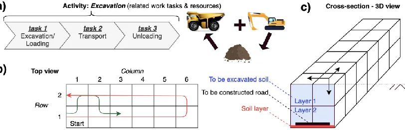
A construction operation can be divided in several independent activities that can be executed separately. Each activity is required to complete a specific part of the operation (the number of activities is depended on the type of operation, the chosen abstraction level and corresponding division of the operation) and consists of several work tasks in a fixed structure and chronological order. For example, ‘road construction’ can be seen as an operation within an infrastructural project. Herein, it is assumed that three different activities need to be executed: 1) excavation 2) preparing the soil layer and 3) paving the asphalt. Each independent activity consists of several work tasks. Excavation, for example, consists basically of three tasks: Excavation/loading, transporting the soil and unloading the soil (Figure 1a). To start this particular activity execution, two resources are required: an excavator and a dumper to transport the excavated soil. When applying this division on the illustrative road construction operation, a planner can form a simple sequence for the three different activities. However, very limited analysis and subsequently optimization is possible.
A ‘to be constructed road’ can be divided into sections to be able to simulate and analyze different execution scenarios. Figure 1a demonstrates the first ‘activity’ for the described operation, the related work-tasks and required resources to execute. The construction environment in this example is divided into six columns and two rows (figure 1b) and two layers (figure 1c). Each section (i.e. 6 sections represented as columns, linked in linear direction) has the same set of independent activities to be completed, including 4 to be excavated blocks (figure 1c). Each independent and similar activity has a certain (physical/technical) relation within the section and with the activities from the next and possibly previous section. For example, one cannot start excavating the second layer without first excavating the block(s) in the upper layer. Furthermore, preparing for example the soil layer for a specific section (the second activity) cannot start until all blocks above and around are excavated. To excavate the total area, 24 similar ‘excavation’ activities are required, but can be put in different sequences. Initially, there are 12 places where the excavator could start (all the cells in the top layer), after which multiple directions and sequence options are possible. Two possibilities (red/green line) are presented in figure 1b, as cell 1.1 (r/c) is chosen to be the first block excavated.
Figure 1a Overview of excavation as activity + work tasks and involved resources 1b Top view of divided road (row/columns) and two sequence alternatives 1c Cross-section 3D view of excavation area with two layers
Level Definition Description
1 Project A temporary effort undertaken to construct a unique product
2 Operation A specific part within the project tied to a certain method that can be seen as separate operation 3 Activities Activities that are required to complete (a part of) the operation
4 Tasks Work tasks (in fixed order) to execute an activity, specific resources are required to fulfill these
[image:6.595.79.485.609.740.2]The example above shows that an operation can be divided in similar sections that require the same activities to be completed. To accurately model such an operation, while considering optional sequences and feasibility constraints, a hybrid-simulation approach is adopted.
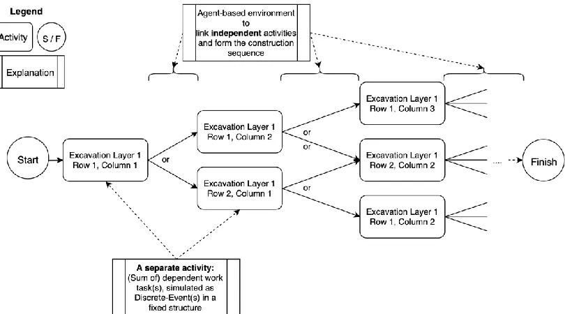
Discrete-event simulation is implemented to simulate each activity independently at task level. Work tasks, required to complete an activity in a fixed structure/sequence, determine the total duration for executing this particular activity for a specific section of the operation. For example, the duration of the exemplar excavation activity in Figure 1a is the sum of durations for task 1 till 3. In DES, durations are generated stochastically, taking uncertainties into account. The independent activity could start once the required resources are available. During execution, these resources are occupied for the generated duration. Hereafter, they are ‘released’ and can start the next activity. Agent-based simulation logic is used to link the independent discrete-event activities (simulations) to incorporate possible sequence alternatives. Based on defined rules, dependencies (relations) between activities within and between separate sections, are modeled. These rules could involve logical constraints (as the demonstrated example of layer 2 which cannot be excavated until the block in the same row/column in layer 1 is finished in Figure 1c) to model only feasible execution sequences. Furthermore, these rules are used to model different sequence alternatives based on different strategies, to generate and subsequently analyze alternatives (i.e. parallel execution of different activities if possible within the working area). The agents in the model, representing the resources required for the activities and the ‘to be constructed’ elements, can be separately controlled by modeling their ‘behavior’ as result of interaction with the environment. This is explained in the figures below.
[image:7.595.80.485.458.683.2]Figure 2 presents different sequence options for similar activities. Excavation of each block in the elaborated example (Figure 1c) presents an activity. It is assumed that there is a single excavator available for the operation and that the first block to be excavated is row 1, column 1 (1.1) in Figure 1b. After finishing block 1.1, the excavator can ‘choose’ between continuing excavating in the same row or moving to row 2. The choices made by the agents form the intended execution sequence. By implying different strategies (e.g. distance, side or layer based) in the agents’ consideration for selecting the next activity, the sequence alternatives can be modelled, making it possible to analyze different options.
Figure 2 Hybrid-simulation set-up for linking similar activities within an operation
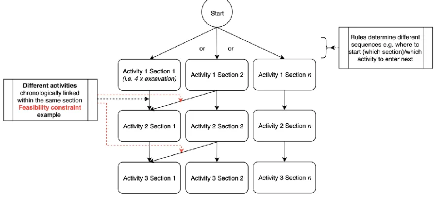
Figure 3 presents the same road construction operation as three activities for the first two sections (plus section n). After completing the excavation for the first section (thus 4 blocks excavated), the section is likely to be ready to enter the next activity (preparing the soil layer). However, it is assumed that when the excavation for section 2 is not finished, the soil preparation cannot start (e.g. due to required work space or soil transportation routes which pass through these sections). Thus, this condition as feasibility constraint for execution can be modelled in the ‘behavior’ of the sections as agents.
Figure 3 Example of different interrelated activities with a feasibility constraint
Finally, an example of four different independent activities is presented in Figure 4. Within an operation, it could be possible that different activities require the same (set of) resource(s). In this example, it is assumed that these four activities have no particular technical or physical relation with each other (e.g. because they are spread across a project’s location). Each activity requires the same crane, of which is one available, complemented with other different resources. This means that with four independent activities, 24 sequences can be followed to execute the operation with the specific crane. Each activity is then simulated separately with DES, while modeling possibly activity selection preference for the crane as agent.
Figure 4 Example of different activities (without relation) that require same resource(s)
[image:8.595.78.415.489.638.2]IV. Scope of the proposed hybrid-simulation
This section reflects on the conceptual modeling process, which sets the scope and briefly identifies the strategy behind implementation and application of the proposed framework. Therefore, example values of agent classification are presented. Subsequently, allocated decision variables for both simulation paradigms are proposed for integrating sequencing alternatives, site lay-out planning, resource allocation and risk management.
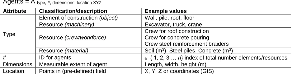
[image:9.595.72.541.354.474.2]As a model is always a simplified representation as (part of) a real system, it is important to determine a certain level of detail (LOD) of the desired in- and output. The LOD sets initially the modeling objectives, the scope of the model and subsequently determines the abstraction level and the division of an operation. This basically consist of partly breaking up a construction operation in independent activities, the related work tasks and required resources. This can be done by making specific (batches) elements of the to be constructed object, as described in the proposed framework. It is assumed that influential parameters from the environment (e.g. soil conditions) are involved in the design, resulting in, for example a certain thickness for a wall, floor or other part of the structure. To model the components within these activities and related resources to execute them, several agents must be created to control their behavior as proposed in the previous section. An overview of example agent types and related attributes is presented in Table 2. A distinction is made for agent types as construction elements and required resources. The latest agent type is thereafter divided in machinery, crews and materials.
Table 2 Example agents + related attributes
Agents = A type, #, dimensions, location XYZ
Attribute Classification/description Example values
Type
Element of construction (object) Wall, pile, roof, floor Resource (machinery) Excavator, truck, crane
Resource (crew/workforce)
Crew for roof construction Crew for concrete pouring Crew steel reinforcement braiders Resource (material) Soil (m3), Steel piles, Concrete (m3)
# ID for agents { 1, 2, 3 … n} index of total number elements/resources Dimensions Measurable extent of agent Length, width, height (m)
Location Points in (pre-defined) field X, Y, Z or coordinates (GIS)
To capture the four proposed planning steps (i.e. sequencing, site lay-out planning, resource allocation and risk management), several decision variables have been allocated. The decisions and corresponding variables are divided in two categories: (1) sequence/site lay-out options for different execution scenarios1 and (2) configurations for durations and execution of
these scenarios (Table 4).
Regarding planning different scenarios, there are several decision variables proposed (Table 3). These decision variables influence the agents’ behavior and determine the execution scenario. First, the start location of the operation (e.g. an activity for constructing the first element with corresponding location). For a road construction operation (Figure 1), this regularly is one of the two ‘ends’ of the road. Second, the transportation strategy for materials. One can think of soil transportation or material supply routes which could traverse the working area and thereby influencing the feasible sequences. In case of the road construction operation, it could be beneficial to transport the excavated soil besides the road, making it possible to accelerate subsequent activities. However, this could involve extra costs or space. Other possible parallel execution within an operation could be involved (this decision is generally made by the contractor: parallel execution is ‘riskier’, requires more resources at the same time, but faster). Resource’ decision preference in choosing next segment/activity could be done randomly, or based on for example distance (e.g. an excavator which selects the closest section/block for its next excavation activity) as explained within the framework.
Finally, for site lay-out planning two variables are considered. First, an important aspect for most construction projects is the place where to dump or load soil due to the (generally involved) earthmoving activities and corresponding transportation tasks. Secondly, the place where idle resources are parked, waiting for their next task(s).
Table 3 Allocated variables and description for planning different scenarios
Planning different scenarios (ABS-variables) Description
Sequence alternatives:
• Start location - GIS location, X,Y,Z point or defined element • Transportation strategy for material handling - Through work area/beside/via certain points/routes • Parallel activity execution - Possible yes/no
• Agents’ choice next activity - Based on: no preference, or condition (e.g. distance) Site lay-out planning:
• Soil dump/load spot - Location (X,Y,Z)
• Parking spot resources - Location (X,Y,Z, length, width)
The second category involves configurations for durations and execution of the different scenarios. These variables consider the settings for the DES part of the proposed model and can be divided in resource allocation and risk management (Table 4). First, the amount of resources (machinery and crews) deployed for the execution process is modeled in the experiment settings. Thereby, capacities for these resources (i.e. transportation capacity of a dumper in m3 or productivity of a certain crew) and corresponding operating times are involved.
[image:10.595.77.528.436.542.2]Through a schedule, belonging to the resource type, the work-shifts and working days (incl. special holidays) are defined. Regarding risk management, two decision variables are integrated. The possibility to model uncertainty in activity duration is involved through a triangular distribution (see Annex B.2) which determined the maximum and minimum value around the average duration. Finally, the effects of occurring risks are implemented within the model to be able to analyze a ‘risk-driven’ schedule. The probability, average effect and type of effect (i.e. stop/delay) are made configurable, as well as the possibility whether to involve specific risks, none or all of them.
Table 4 Allocated variables and description for executing scenarios
Scheduling scenario execution (DES-variables) Description
Resource allocation:
• Amount resources - Number of machine type or crew
• Type/capacity resources - Capacity/speed machine or crew
• Operating times resources - Number of working hours per day (i.e. 8/16/24 hrs.) Number of working days per week (5/6/7 days). Risk management:
• Uncertainty activity duration - Triangular distribution gradation (see Annex B.2) • Occurring risks - Effect (time) of related risk(s)
V. Implementation and case study
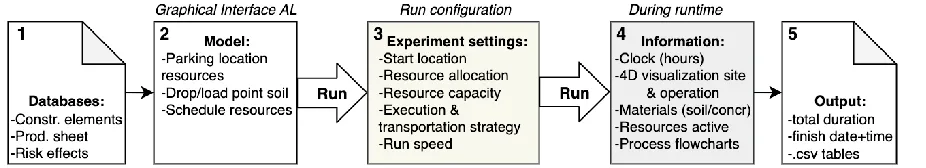
The proposed approach, including the decision variables, is implemented in Anylogic simulation software. The user interface is presented in Figure 5. The model structure can be subdivided into five parts (Figure 5). Part 1-3 contains the ability to change the simulation outcomes: (1) the input from databases with information about the construction elements and activity durations (i.e. production sheet and risk report), (2) the graphical interface in Anylogic for defining site lay-out planning and schedules, (3) the experimental settings after initiating the model (i.e. the DES-variables). Thereafter, during runtime, (4) progress information can be acquired and viewed and finally, (5) the output of a simulation run.
[image:10.595.72.535.664.748.2]The case study is executed in two stages. First, the modelling approach was set-up in Anylogic as described above to simulate a simplified cut & cover tunneling operation. Thereafter, the model is applied to an existing tunneling operation currently in development. The results of the latest simulation are therefrom compared with the actual operation for validation.
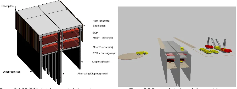
[image:11.595.70.343.193.318.2]The scope of the case study focusses on constructing the structural elements of a cut & cover tunnel (i.e. finishing works and inner road construction not incorporated) with a ‘quick backfill’ strategy. Herein, diaphragm walls as retaining walls and segments in between (including roof and floor) are considered. Figure 6 represents a simplified cut & cover tunnel with the involved structural elements.
Figure 6 Simplified cut & cover tunnel design
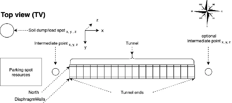
To be able to match the model output with the level of detail (LOD) of an ordinary cut & cover schedule, the tunneling operation was initially modeled as 13 proposed activities with corresponding work tasks (presented in Annex B.1). The proposed activities conformed to the total operation and form the ‘quick backfill’ cut & cover strategy (i.e. not ‘bottom-up’, which involves first total excavation and then floor, roof, backfill) for one particular segment as integrated in the model. Figure 7 presents an overview of the site lay-out for the simplified cut & cover model.
Figure 7 Site lay-out for simplified tunneling model
[image:11.595.75.475.431.610.2]Figure 8.1 3D BIM sketch case study tunnel Figure 8.2 Screenshot of simulation model
Within the case study, all decision variables are implemented. For sequence alternatives, site lay-out planning and risk management (thus without the DES-variables for resource allocation, i.e. amount resources, type and operating times) this resulted in the following number of scenarios:
𝑁𝑢𝑚𝑏𝑒𝑟 𝑜𝑓 𝑝𝑜𝑠𝑠𝑖𝑏𝑙𝑒 𝑠𝑐𝑒𝑛𝑎𝑟𝑖𝑜𝑠 𝑤𝑖𝑡ℎ𝑜𝑢𝑡 𝑟𝑒𝑠𝑜𝑢𝑟𝑐𝑒 𝑐𝑜𝑚𝑏𝑖𝑛𝑎𝑡𝑖𝑜𝑛𝑠 ∏ 𝑁𝑖 = 337.920
𝑛 = 8
𝑖=1
Wherein:
𝑛 = 𝑛𝑢𝑚𝑏𝑒𝑟 𝑜𝑓 𝑑𝑒𝑐𝑖𝑠𝑖𝑜𝑛 𝑣𝑎𝑟𝑖𝑎𝑏𝑙𝑒𝑠 𝑖𝑛𝑣𝑜𝑙𝑣𝑒𝑑
𝑁𝑖 = 𝑛𝑢𝑚𝑏𝑒𝑟 𝑜𝑓 𝑝𝑜𝑠𝑠𝑖𝑏𝑙𝑒 𝑣𝑎𝑙𝑢𝑒𝑠 𝑓𝑜𝑟 𝑑𝑒𝑐𝑖𝑠𝑖𝑜𝑛 𝑣𝑎𝑟𝑖𝑎𝑏𝑙𝑒 𝑖
For resource allocation, 11 types are integrated for which each resource has 9 combinations for operating times (working shifts and days as proposed, as 12th decision variable). With the
resource values 𝑖 as presented in Table 5 and available resources to deploy the following equation is set up to calculate the number of possible scenarios:
𝑁𝑢𝑚𝑏𝑒𝑟 𝑜𝑓 𝑝𝑜𝑠𝑠𝑖𝑏𝑙𝑒 𝑟𝑒𝑠𝑜𝑢𝑟𝑐𝑒 𝑐𝑜𝑚𝑏𝑖𝑛𝑎𝑡𝑖𝑜𝑛𝑠 𝑓𝑜𝑟 𝑒𝑥𝑒𝑐𝑢𝑡𝑖𝑜𝑛 ∏ 𝑁𝑖 = 248.832
𝑛 = 12
𝑖=1
Wherein:
𝑛 = 𝑛𝑢𝑚𝑏𝑒𝑟 𝑜𝑓 𝑟𝑒𝑠𝑜𝑢𝑟𝑐𝑒 𝑡𝑦𝑝𝑒𝑠 𝑖𝑛𝑣𝑜𝑙𝑣𝑒𝑑(11 types, see Table 5)
[image:12.595.70.522.537.655.2]𝑁𝑖 = 𝑛𝑢𝑚𝑏𝑒𝑟 𝑜𝑓 𝑝𝑜𝑠𝑠𝑖𝑏𝑙𝑒 𝑣𝑎𝑙𝑢𝑒𝑠 𝑓𝑜𝑟 𝑟𝑒𝑠𝑜𝑢𝑟𝑐𝑒 𝑡𝑦𝑝𝑒 𝑖
Table 5 Resource (agent) types as modelled for the case study
Attribute Classification/description Values # Resources avail.
Type
Resource (machinery, resource pool)
Excavator Dumper
DiaphragmWall Crane Help Crane
Dozer
1 – 2 1 – 6 1 – 3 1 – 2 1 – 2
Resource (crew/workforce, resource pool)
CrewRoof CrewFloor CrewDiaWall CrewConcrete CrewStruts CrewPurlin
2 / 4 2 / 4 1 – 3 1 – 2 1 – 4 1 – 2
Therefrom, it can be concluded that for the case study project, with the decision variables involved as described above, the following number of scenarios can be generated:
𝑇𝑜𝑡𝑎𝑙 𝑛𝑢𝑚𝑏𝑒𝑟 𝑜𝑓 𝑒𝑥𝑒𝑐𝑢𝑡𝑖𝑜𝑛 𝑠𝑐𝑒𝑛𝑎𝑟𝑖𝑜𝑠 ∏ 𝑁𝑖 8.4 ∗ 1010
𝑛 = 20
The case study demonstrated, that many scenarios (i.e. a large solution space) could be generated in a short amount of time. Namely, running the case study model took approximately 2 minutes at virtual run-speed (used processer: 2GHz Intel Core i5). After calibration (i.e. scenario with roughly equivalent input: production sheet with average cycle times and resource allocation for execution), the model was quantitatively validated with the original schedule for the sub-project. The model outcomes showed some differences in activity execution in combination with resource utilization. These differences were caused due to the fact that execution planners deploy different sets of resources at and for different times. For example, more crews were deployed in the early phase of the project, while later reduced which is currently not incorporated in the model (i.e. same set of resources deployed for the total operation). Furthermore, durations for activities (with the same number of resources) deviated from the original schedule, caused by the transportation times which are not incorporated in the original schedule. The total simulated duration in working days was less than 5% more compared to the original schedule. Application of the model and the case study results are intensively discussed with experts in a group interview. Results of this assessment session for qualitatively validating the model are summarized in the next section.
Validation criteria assessment
Several validation criteria for qualitatively model assessment are composed and summarized in Table 6. In the group interview, results of the case study are presented to a risk-manager, an execution planner, a (digital) project information manager and an underground infrastructure expert to acquire various perspectives and form an integral assessment.
Validation criterium Specification
• Ease of use
- Model interface
- Degree insight model steps/logic
- Degree insight in process/progress during runtime
• Configurability - To what extent input and settings can be defined and adapted - Run duration
• Integrity - Level of capturing (variating) information at certain LOD (e.g. occurring risks and effects + uncertainties in activity durations) and processability
• Output - Convertibility of generated data - Accuracy and reliability of data
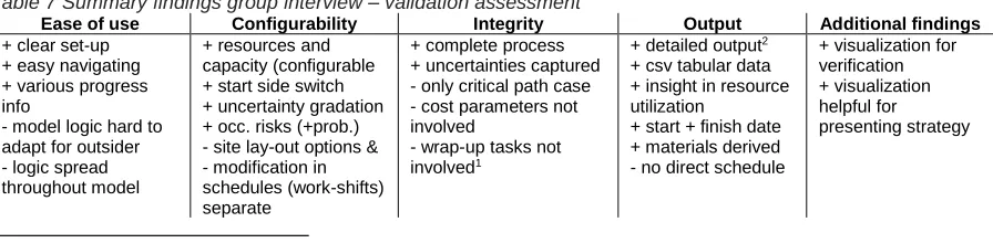
[image:13.595.76.524.632.742.2]The experts argued that configuration settings for the incorporated decision variables are made clear and easy to adapt. This enables execution planners to quickly change, re-generate and analyze a particular scenario, while normally many calculations have to be made manually. Furthermore, during runtime navigating through the model provides various progress information (e.g. resources active, transported soil or poured concrete over time) which provides the ability to quickly optimize resource allocation. The visualization of the simulation is useful for verification of the process and could support presenting strategies to clients or contractors. Changing the logic at a specific place in the model for the entire process (i.e. a condition for all construction elements) is reviewed as beneficial with respect to current used planning procedures. However, adapting this logic was also criticized due to the fact that software knowledge is required. Moreover, the rules are spread throughout the entire model, which makes it difficult for an outsider to change them quickly. The output of the model was valued as detailed and accurate. Yet, it takes some time to structure all the information and create a related Gantt-chart or other schedule. Table 7 presents a summary of the findings.
Table 7 Summary findings group interview – validation assessment
Ease of use Configurability Integrity Output Additional findings + clear set-up
+ easy navigating + various progress info
- model logic hard to adapt for outsider - logic spread throughout model
+ resources and capacity (configurable + start side switch + uncertainty gradation + occ. risks (+prob.) - site lay-out options & - modification in schedules (work-shifts) separate
+ complete process + uncertainties captured - only critical path case - cost parameters not involved
- wrap-up tasks not involved1
+ detailed output2 + csv tabular data + insight in resource utilization
+ start + finish date + materials derived - no direct schedule
+ visualization for verification + visualization helpful for presenting strategy
1Some activities cannot be stopped for a weekend and then continued after. Wrap-up tasks will take additional time.
2Output shows that transportation activities further away from the start location take more time than closer segments, this is not incorporated in original
VI. Discussion & lessons learned
The hybrid-simulation modeling approach can efficiently capture multiple planning steps at once. Therefore, it provides an integral framework for simulating the planners’ logic in complex environments which integrates planning and scheduling procedures. The involved decision variables result in an extensive amount of execution scenarios. The output enables planners to quickly analyze various options without eliminating feasible execution scenarios throughout sequential planning steps. Despite the advantages, there are some issues raised that require critical reflection which will be covered in this section. Furthermore, evaluation on possible model extensions and improvements are discussed.
Reflecting on the process, extensive effort is required to conceptually model an operation and streamline the required input for the corresponding model. Conceptually modeling an operation involves many steps and calculations to align the format and values of information (e.g. production sheet to work hours, specific design parameters from segments to productivity/capacity in square meters for the crews) from different databases (e.g. production sheets, agent attributes, risk report). For example, activity durations have to be precisely aligned to make them usable for a simulation model (i.e. recalculated or derived from activity level and other input, to be at work task level). Besides, the relations between the activities (e.g. feasibility constraints) have to be determined and laid down in rules. This effort could be a threshold for application, since convincing planners up front with benefits of diverging approaches seems to be an essential step in improving or renewing procedures [10]. Regarding the in- and output of the model, accurate data should be involved to create reliable and realistic schedules in terms of activity durations and resource productivity. When more as-built data is acquired and thereafter made available for modeling and planning construction operations, more realistic schedules could be created. Misinformation of such productivity and cycle times still causes many infrastructural projects overrun regarding time and cost [24]. Sample-based distributions could be used to incorporate uncertainties instead of using triangular values. However, incorporating the used production sheets from contractors with average activity durations in the case study, resulted in a more realistic and accurate execution schedule due to the in the simulation involved transportation times.
Furthermore, several decision variables per planning step are proposed. These could be supplemented with others. For example, integrating interrelated (continuous) variables to the model, like, material flows or productivity rates for resources, could make the simulation more accurate. Materials for example are now seen as derivatives of the construction process and not limited. In practice, for example, concrete supply is a restricting factor for pouring large concrete elements. Also, for site lay-out planning, more variables such as different supply routes and surrounding constraints (e.g. speed limits, limit of vibrations) could be implemented to improve the accuracy of the model. Finally, cost parameters could be incorporated in the model to optimize the financial aspects of the project.
VII. Conclusions & recommendations
This paper proposed a comprehensive hybrid-simulation modeling approach that improves the efficiency of (pre-) construction planning procedures by achieving concurrent planning. The proposed framework incorporates multiple planning steps simultaneously and is able to generate many different execution scenarios while obtaining significant benefits in terms of time and effort with respect to conventional planning approaches. The proposed framework integrates several decision variables regarding sequencing, site lay-out planning, resource allocation and risk management. This allows planners to evaluate different planning scenarios simultaneously, as input for a better substantiated execution schedule.
The feasibility of the approach has been explored through a case study. Experts working on this project argue that much detailed and accurate information is generated in a short amount of time. The benefits show for example that, easy modification of decision variables in run-configurations quickly resulted in accurate and detailed schedules. Therefrom, it can be concluded that the model provides a powerful, convenient and practical manner for analyzing different planning scenarios.
Future works will need to investigate integration of other relevant decision variables to include more concurrent planning steps and subsequently extent the number of possible scenarios. For example, operation expenditures could be integrated to generate cost estimations. This provides the ability to optimize an operation in a broader perspective. Furthermore, the application of the method for different types of construction operations will have to be further explored.
Acknowledgements
References
[1] S.-M. Chen, F. H. (Bud) Griffis, P.-H. Chen, and L.-M. Chang, “A framework for an automated and integrated project scheduling and management system,” Automation in Construction, vol. 35. pp. 89–110, 2013.
[2] W. Jeong, S. Chang, J. Son, J.-S. Yi, E. U. (Department of Architectural Engineering, and A. (School of Building Construction, Georgia Institute of Technology North Avenue, “BIM-Integrated Construction Operation Simulation for Just-In-Time Production Management,” Sustain. MDPI, vol. 8, 2016.
[3] V. Faghihi, A. Nejat, K. F. Reinschmidt, J. H. Kang, and I. (University of Technology, Tehran, “Automation in construction scheduling- a review of the literature,” Adv. Manuf. Technol., vol. 81, pp. 1845–1856, 2015.
[4] D. Heesom, L. Mahdjoubi, and U. of W. (School of Engineering and the Built Environment, “Trends of 4D CAD applications for construction planning,” Constr. Manag. Econ., vol. 22:2, pp. 171–182, 2004. [5] W. C. Wang, S. W. Weng, S. H. Wang, and C. Y. Chen, “Integrating building information models with
construction process simulations for project scheduling support,” Automation in Construction, vol. 37. pp. 68–80, 2014.
[6] C. Markou, G. K. Koulinas, A. P. Vavatsikoos, and D. U. of T. (Production and Management Engineering Dept., “Project resources scheduling and leveling using Multi-Attribute Decision Models- Models
implementation and case study,” Expert Syst. Appl., vol. 77, pp. 160–169, 2017.
[7] D. K. H. Chua, T. Q. Nguyen, K. W. Yeoh, and N. U. of S. (Dept. of Civil and Environment Engineering, “Automated construction sequencing and scheduling from functional requirements,” Autom. Constr. Elsevier, vol. 35, pp. 79–88, 2013.
[8] E. Tauscher, K. Smarsly, M. König, K. Beucke, and G. (Bauhaus University Weimar, “Automated Generation of Construction Sequences using Building Information Models.”
[9] H. Kim, K. Anderson, S. Lee, and J. Hildreth, “Generating construction schedules through automatic data extraction using open BIM (building information modeling) technology,” Automation in Construction, vol. 35. pp. 285–295, 2013.
[10] S. Miller, A. Dorée, and (University of Twente), “What can we learn from the planner’s logic?,” ARCOM Conf., vol. Associatio, pp. 381–390, 2008.
[11] N. Fu, H. C. Lau, P. Varakantham, and S. M. U. (School of Information Systems, “Robust execution strategies for project scheduling with unreliable resources and stochastic durations,” J Sched, vol. 18, pp. 607–622, 2015.
[12] J. I. Kim, M. Fischer, and C. Kam, “Generation and evaluation of excavation schedules for hard rock tunnels in preconstruction and construction,” Autom. Constr., vol. 96, pp. 378–397, 2018.
[13] S. Moradi, F. Nasirzadeh, and F. Golkhoo, “A hybrid SD–DES simulation approach to model construction projects,” Constr. Innov., vol. 15, no. 1, pp. 66–83, 2015.
[14] J. D. Sterman, “System Dynamics Modeling for Project Management,” Unpubl. Manuscr., vol. 1951, pp. 286–294, 1992.
[15] D. Halpin and L. Riggs, “PLanning and Analysis of Construction Operations.pdf.” 1994.
[16] S. Han, S. H. Lee, and M. Park, “Dynamic Project Management: An Application of System Dynamics in Construction Engineering and Management,” Intelligent Systems, Control and Automation: Science and Engineering, vol. 72. pp. 219–231, 2014.
[17] C. Kim, C. Kim, and H. Son, “Automated construction progress measurement using a 4D building information model and 3D data,” Automation in Construction, vol. 31. pp. 75–82, 2013.
[18] M. Mawlana, F. Vahdatikhaki, A. Doriani, and A. Hammad, “Integrating 4D modeling and discrete event simulation for phasing evaluation of elevated urban highway reconstruction projects,” Automation in Construction, vol. 60. pp. 25–38, 2015.
[19] N. Fachaca, V. V. Lopes, R. C. Martins, A. C. Rosa, and U. de L. (Institute for Systems and Robotics, LARSyS, Instituto Superior T´ecnico, “Towards a standard model for research in agent-based modeling and simulation,” PeerJ Comput. Sci., vol. 36, 2015.
[20] S. Razavialavi and S. Abourizk, “A hybrid simulation approach for quantitatively analyzing the impact of facility size on construction projects,” Automation in Construction, vol. 60. pp. 39–48, 2015.
[21] J. Y. Ruwanpura and S. T. Ariaratnam, “Simulation modeling techniques for underground infrastructure construction processes,” Tunnelling and Underground Space Technology, vol. 22, no. 5–6. pp. 553–567, 2007.
[22] S. AbouRizk, “Role of Simulation in Construction Engineering and Management,” Constr. Eng. Manag., vol. 136, pp. 1140–1153, 2010.
[23] J. P. Vargas, J. C. Koppe, and S. Pérez, “Monte Carlo simulation as a tool for tunneling planning,” Tunn. Undergr. Sp. Technol., vol. 40, pp. 203–209, 2014.
Annex A
Simplified representation of cut & cover tunneling:
Annex B
B.1) Division of operation for implementation (activities & work tasks):