warwick.ac.uk/lib-publications
Original citation:Dinh, T. Q., Marco, James, Greenwood, D., Harper, L. and Corrochano, D. (2016) Powertrain modelling and engine start control of construction machines. In: 3rd International
Conference on Powertrain Modelling and Control Testing, Mapping and Calibration, Loughborough University, UK, 7-9 Sep 2016
Permanent WRAP URL:
http://wrap.warwick.ac.uk/81454
Copyright and reuse:
The Warwick Research Archive Portal (WRAP) makes this work by researchers of the University of Warwick available open access under the following conditions. Copyright © and all moral rights to the version of the paper presented here belong to the individual author(s) and/or other copyright owners. To the extent reasonable and practicable the material made available in WRAP has been checked for eligibility before being made available.
Copies of full items can be used for personal research or study, educational, or not-for-profit purposes without prior permission or charge. Provided that the authors, title and full
bibliographic details are credited, a hyperlink and/or URL is given for the original metadata page and the content is not changed in any way.
A note on versions:
The version presented here may differ from the published version or, version of record, if you wish to cite this item you are advised to consult the publisher’s version. Please see the ‘permanent WRAP URL’ above for details on accessing the published version and note that access may require a subscription.
Powertrain Modelling and Engine Start Control of Construction Machines
T.Q. Dinh1,*, J. Marco1, D. Greenwood1, L. Harper2, D. Corrochano2
1WMG, University of Warwick, Coventry CV4 7AL, UK; [email protected];
2JCB, Rocester, Staffordshire, ST14 5JP, UK; [email protected]; [email protected]
* Correspondence: [email protected]; Tel.: +44-2476-574902
Abstract:This paper aims to develop an engine start control approach for a micro/mild hybrid
machine for a capable of cranking the engine without injection. First, the powertrain is physically
modelled using a co-simulation platform. Second, experiment data of the traditional machine is
acquired to optimize the model. Third, a model-based adaptive controller is designed for the starter
to crank the engine quickly and smoothly to minimize the operator discomfort. The effectiveness
of the proposed approach is validated through numerical simulations with the established model.
Keywords— Construction machine, modelling, optimization, start control.
1-Introduction
Construction industry is ranked third just behind oil and gas and chemical manufacturing sectors in terms of having influence on the greenhouse effect. Additionally, energy crisis becomes more and more serious in recent years while fuel consumption of these equipment accounts for a significant portion of total global fuel usage. Thus, improving efficiency of construction equipment is very important and is one of the key factors for creating a clean environment and saving energy.
hybrid equipment is still limited. Herein to save energy, two important tasks are an engine start control approach and, determination of engine idle state to define when the engine can be switched to idle or turned off [3, 4]. To address the first task, a controller needs to be properly designed to start the engine quickly and smoothly to reduce impacts of machine noise, vibration and harshness (NHV), due to large inertia and peak compression torque of the engine, on the driver comfort.
This paper focuses on the design of engine start control for micro hybrid construction machines. Powertrain of a typical excavator has been selected for the study. Here, the traditional starter is replaced with a larger electric motor for a capable of cranking the engine directly from zero speed without the use of injection. First, the powertrain is physically modelled using AMESim and then, embedded into Simulink to perform the co-simulation platform. Second, experiment data with the selected machine is acquired to optimize the model. Third based on the optimized model, a model-based adaptive controller which is the combination of an inverse model and a proportional-integral (PI)-based adaptive controller is constructed to drive the starter to enhance the quick and smooth engine start. Simulations have been carried out to evaluate the capability of the designed controller.
2-Powertrain Architecture and Co-Simulation Platform
Starter
HDT
HST
C
BAT
Servo
Controller ServoDrive Excitation System (Voltage Regulator +
Power Stabilizer)
VREF
Converter
wS_REF
Energy Mechanic Signal
STARTING CONTROL STORAGE MANAGEMENT UNIT
ICE
F L W
[image:3.612.188.451.320.429.2]Alternator
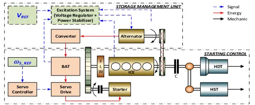
Fig. 1. Powertrain configuration of a generic construction machine
The powertrain architecture of a generic machine can be described in Fig. 1. Here, the power system mainly consists of the ICE, starter and alternator. The starter is engaged to the engine using the pinion-ring gear mechanism (integrated a flywheel) via an over-running clutch. The output shaft of the engine is coupled to the alternator with a belt transmission. The electricity created by the alternator is stored in the battery which is used to supply power for the starter. The drivetrain, work hydraulics and other auxiliaries are assumed as a combination of a hydrodynamic transmission and a hydrostatic transmission connected to the engine output shaft through a clutch. These parts can be simplified as a dynamic load simulator with adjustable inertia. For engine start control, this dynamic load can be neglected or approximated as a small constant load.
AMESim and MATLAB/Simulink is suggested. AMESim is the advanced simulation tool which provides sufficient libraries for physical modelling approaches which eliminate the tedious mathematical modelling, code programming while ensure high modelling efficiency [5]. The main drawback of using AMESim is control system design. Meanwhile, MATLAB/Simulink is the powerful tool for control system design, modelling and optimization. Thus, the co-simulation using these tools is a feasible solution for powertrain modelling and control.
3-Powertrain Modelling
3.1-Engine Model
The four-stroke diesel engine model was firstly constructed to estimate the engine transient response. As shown in Fig. 2(a), this engine block mainly includes following components: four combustion cylinders which were linked together to a crankshaft; intake and exhaust mechanisms with compressor, intercooler, throttle and exhaust gas recirculation (EGR).
Compressor Turbine
Combustion Cylinder Crankshaft Intake
Manifold
Exhaust Manifold EGR
Intercoller
Throttle
Injector
(a)
(b)
Fig. 2. Four-stoke internal combustion engine: (a) Configuration; (b) Model built in AMESim
By using AMESim and thermodynamic analysis [7-8], the engine physical model was built as in Fig. 2(b). To estimate the engine transient behaviour, the model inputs can be listed as:
Combustion cylinder: coolant temperature, temperature and pressure of the injected fuel, start
Intake and exhaust mechanisms: intercooler control signal throttle control signal, variable geometry turbine position, engine torque request, engine speed
3.2-Starter, Alternator and Battery Models
Electric components in the powertrain used for the engine cranking operation are a DC motor with direct current drive, a DC output generator and a lead-acid battery. By using AMESim, the equivalent electrical circuit of a direct current machine with permanent excitation was used to model this motor in which the inputs are temperature, supply voltage and load torque, and the outputs are current and rotational speed. Meanwhile, the alternator with DC output was represented as an average model of current generator with external voltage regulation. The model inputs are temperature, rotational speed, storage voltage and desired voltage while the outputs are torque and storage current. The lead-acid battery was modelled by an equivalent electric circuit of variable voltage source and variable resistance which are function of the state of charge (SOC) and temperature. These component models are shown in Fig. 3.
(a) (b) (c)
Fig. 3. Electric component models: (a) Starter motor; (b) Alternator; (c) Battery
3.3-Transmission and Load Models
The pinion-ring gear mechanism was modelled as a gear transmission connected to a controllable clutch. Additionally, the integrated flywheel was presented by a constant rotary load while all the friction losses through this transmission was presented by a friction mean effective pressure model (Fig. 4(a)). By assuming that there was no extension or damage of belt, the belt transmission model was a set of a two-input-one-output rotary node, a gear transmission with fixed ratio and a rotary spring-damper as in Fig. 4(b). As mentioned in Section 2, the loads at the engine output shaft could be represented by a constant small rotary load with another rotary spring-damper (Fig. 4(c)). As a result, the powertrain model was completely build as displayed in Fig. 5.
(a) (b) (c)
Fig. 4. Transmission and load models: (a) Gear transmission; (b) Belt transmission; (c) Loads
3.4-Power System Control Signal and Logics
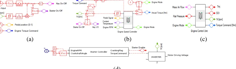
The control signals and logics designed for the power system model as shown in Fig. 6 consist of:
Input signals: key On/Off event, pedal position, and engine torque command which were
Engine speed controller bases on the input signals and current engine speed to define the engine torque request and engine modes. Here, the engine operation was basically classified into four modes: engine start with injection, injection off, idle, and normal power.
Engine control unit uses the defined mode to control the combustion process with air flow, rail
pressure and injection.
Starter control unit: in case of traditional design, there was only the direct connection between
[image:6.612.125.502.179.378.2]the motor and power supply models. An electric switch was used to turn on or off this motor. Conversely in micro hybrid model, the motor speed was controlled by the proposed controller, build in Simulink, via the inverter model.
Fig. 5. Complete powertrain model of a generic construction machine built in AMESim
(a) (b) (c)
(d)
Fig. 6. Model’s control: (a) Inputs; (b) Engine speed controller; (c) Engine control unit; (d) starter control unit
4-Model Optimization
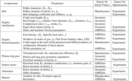
[image:6.612.115.526.412.532.2]Table 1 – Model parameters and sources for parameter setting and optimization
Components Parameters Source for
Initial Values
Source for Optimization
Belt
Pulley diameters,Dp1,Dp2
Pulley moment of inertia,Ip1,Ip2
Belt damping coefficient and stiffness,cB,kB
Manufacturer Experiment
Experiment
Engine mechanism
Crank arm length,Rcank
Rod length,Lrod, cylinder: bore diameter,Dbore, clearance,Lclear
Compression ratio,Ccom, stroke,Scyl
Equivalent engine inertia,IE
Static and dynamic friction parameters
Geometry Geometry Geometry Geometry AMESim Experiment Experiment Engine thermodynamics
Fuel density,
f, Specific heat ratio, Numbers of moles of gas,ng, Fuel lower heating value,LHVf
Crank angle at the start of the premixed and diffusion phases of combustion, Duration of these phases
Weibe parameter set
AMESim AMESim Manufacturer AMESim Experiment Experiment Experiment Experiment Pinion-ring gear
Transmission ratio,RG, transmission efficiency,G Pinion and ring gear geometric parameters Flywheel moment of inertia,IF
Manufacturer Geometry Geometry
Experiment
Experiment
Starter motor Resistant load,RS, armature conductance,LS, armature gain,kS Rotor moment of inertia,Is
AMESim
Geometry Experiment
Alternator Rotor moment of inertia,IA
Other dynamics
Geometry
AMESim Experiment
Battery Number of cells, Nominal capacity
Resistance
Manufacturer
[image:7.612.106.541.78.347.2]AMESim Experiment
Table 2 – Procedure and method for powertrain model optimization
Step Test Conditions Model Input / Output
and Data Method
Step 1 - Parameterization and validation for Starter –
Engine model
Without injection
Without connecting to
alternator
Input: key event
Output: battery output voltage
Parameter estimation toolbox for optimizing parameters of battery, starter, starter-engine inertia
Step 2 - Parameterization and validation for Starter – Engine – Alternator model
Without injection Input: key event
Output: battery output voltage
Parameter estimation toolbox for optimizing parameters of alternator inertia
Step 3 - Parameterization and validation for full
powertrain model
Connecting all
component
Injection was enabled
Input: engine
torque
Output: engine
speed
Parameter estimation toolbox for optimizing parameters of combustion process (thermal dynamics)
Based on Table 1, the powertrain model was optimized using the nonlinear least square-based parameter estimation and the experimental data. The procedure to optimize the powertrain model was performed with three steps as shown in Table 2. Here, the experiments in Table 2 were
cranking tests with the researched excavator in the normal working temperature, around 25oC. The
plotted in Fig. 7(b). The results imply that the model has enough capability to estimate the powertrain dynamics.
[image:8.612.110.528.93.227.2](a) (b)
Fig. 7. Modelling result using the powertrain model: (a) Optimization result; (b) Validation result
5-Engine Start Controller
Desired Engine Idle RPM
StarteAltern ato
r-Engine PI-Type
Adaptive Controller Inverse Eng ine
Model
Motor Driver
Distur bances
+
wE
- +
+
wEr
wE
qE
tE
tC tS uS
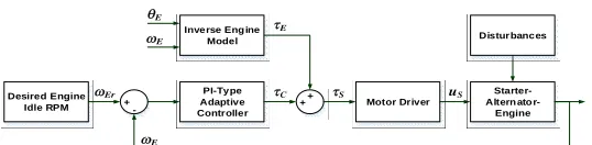
Fig. 8. Proposed model-based control architecture for engine start
The proposed engine start controller is described in Fig. 8. From Section 4, the optimized model of the traditional powertrain could simulate well the cranking performance and therefore, it is useful for powertrain dynamics investigation. However for control applications, this complex model is hardly to be used. In order to build the proposed controller for the micro hybrid powertrain using the larger starter, the powertrain model was simplified and utilized as following steps:
Step 1: the AMESim model was packaged as a black-box model and embedded into Simulink
as an S-function with a mask of the key parameters;
Step 2: a linear model is derived using a set of the Simulink model input-output data and
identification toolbox of MATLAB;
Step 3: an inverse model was created in which the model inputs are the engine speed and
crankshaft angle while the output is the estimated load torque applied to the starter motor shaft.
[image:8.612.184.453.298.364.2]u, andnoutputs (in this case,uC;n=1). This network consists of three layers: an input layer as
a control error sequenceekNN { ,...,e1k ekn1}
, i desired i, actual i,
k k k
e y y , a hidden layer with two nodes, P
and I, following PI algorithm, and an output layer to compute the control input. Define{ Pi, Ii}
k k
w w
is a weight vector of the hidden nodes with respect to inputith, and{w wkP, kI}is the weight vector of
the output layer. Therefore, the output from each hidden node is derived based on PI algorithm:
1 1
1
1 : Node P; 1 : Node I
n n
P Pi i I I Ii i
k i k k k k i k k
O
w e O O
w e (1)Then, the output from the network is obtained using a linear function:
NN
NN P P I Ik k k k k k k
u f O O w O w O (2)
To ensure the robust control performance, the back-propagation algorithm based on the Lyapunov stability condition was derived to tune the network weights. Define a prediction error function as
2
21 , , 1
1 1
0.5 n 0.5 n .
NN desired i actual i i
k i k k i k
E
y y
e (3)By letting{w wkP, kI}to unit, the hidden weights can be online tuned for each step, (k+1)th, as follows:
1 /
Pi or Ii Pi or Ii Pi or Ii NN Pi or Ii
k k k k k
w w E w (4)
where
kPi, kIiare learning rates within [0,1]; the other factors in (4) are derived using partialderivative of the function (3) with respect to each decisive parameter and chain rule method [9].
Lyapunov stability condition: by selecting properly the learning rates
kPi
kIi kfor step (k+1)thto satisfy (5), then the stability of the PI-based adaptive controller is guaranteed.
1 2
1 0.5 0
n i
k k k k i e F F
(5) 1 1 .j NN j NN
n
k k k k
k Pi Pj Ii Ij
j k k k k
e E e E
F
w w w w
Proof:by defining a Lyapunov function as (6), the change of this function is derived as (7)
2
21 , , 1
1 1
0.5 n 0.5 n .
NN desired i actual i i
k i k k i k
V
y y
e (6)
2 2 11 1 1
2 1
1 1
0.5
0.5 , .
n
NN i i
k i k k
n i i i i i i
k k k k k k
i
V e e
e e e e e e
From the PI-based controller structure, one has: 1 1 . i i n
i k Pj k Ij
k Pj k Ij k
j k k
e e
e w w
w w
(8)Terms Pj, Ij
k k
w w
are from (4). By using partial derivative and selecting
kPj
kPj
k, (8) becomes:.
i k k k
e
F (9)
From (9), (7) is rewritten as
1 2
1 1 0.5 .
n
N N i
k i k k k k
V e F F
(10)The tracking performance is guaranteed to be stable only if 1 0,
NN k
V k
. It is clear that except
k
, the other factors in (10) can be determined online based on the prediction error and the chain
rule method [9]. Hence for each working step, it is easy to select a proper value of
k to make (5)satisfy. Therefore, the proof is completed.
6-Simulation Results
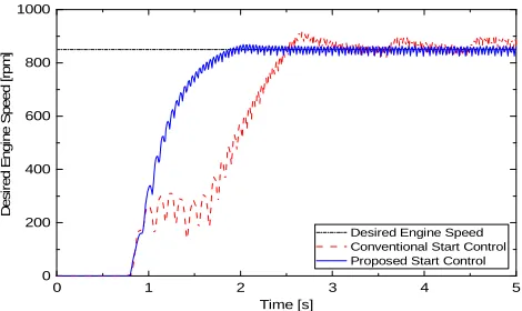
Numerical simulations with transient responses during engine start using the tradition concept with starter-injector and the hybrid concept with only the controlled starter have been carried out. Here, the desired cranking speed was 850rpm. A comparison of the simulation results has been made as plotted in Fig. 9. The comparison indicates convincingly that the engine was start quickly and smoothly by using only the starter and model-based adaptive controller. The influence of engine dynamics was reduced by the inverse engine model while the desired speed was guaranteed by the adaptive feedback control. As a result, the NVH performance could be well managed and therefore, the driver comfort as well as fuel economy could be improved.
0 1 2 3 4 5
0 200 400 600 800 1000 D e s ir e d E n g in e S p e e d [r p m ] Time [s]
[image:10.612.202.437.492.632.2]Desired Engine Speed Conventional Start Control Proposed Start Control
7-Conclusions
In this paper, the method for starting engine without compromising the NVH performance has been
introduced for micro/mild hybrid construction machines. The machine powertrain model was
developed and optimized using the advanced co-simulation between AMESim and
MATLAB/Simulink. This model enables users to easily explore the engine and powertrain
dynamics including transient responses as well as to linearize with selected characteristics to
support control design. To improve the machine efficiency, the model-based adaptive controller
using PI-type neural network was built to ensure the robust engine cranking performance.
References:
1. Robinette, D. and Powell, M. Optimizing 12 Volt Start - Stop for Conventional Powertrains,
SAE Int. J. Engines, December 2011, 4(1), 850-860, doi:10.4271/2011-01-0699.
2. Kum, D., Peng H. and Bucknor, N. K. Control of Engine-Starts for Optimal Drivability of
Parallel Hybrid Electric Vehicles, J. Dyn. Sys., Meas., Control, March 2013, 135(2).
3. Park, K. S., Kim, S. I. and Jeong H. J. Low Idle Control System of Construction Equipment
and Automatic Control Method Thereof, US patent, October 2013, US 2013/0289834 A1.
4. Frelich, T. A. Autoadaptive Engine Idle Speed Control, US patent, February 2014, US
2014/0053801 A1.
5. Truong, D. Q. and Ahn, K. K. Force control for hydraulic load simulator using self-tuning
grey predictor – fuzzy PID, Journal of IFAC, Mechatronics, March 2009, 19(2), 233-246.
6. Rakopoulos, C. D. and Giakoumis, E. G. Diesel engine transient operation: Principle of
operation and simulation analysis, Springer-Verlag London Limited, Springer 2009.
7. Ipci, D. and Karabulut, H. Thermodynamic and dynamic modeling of a single cylinder four
stroke diesel engine, App. Math. Modelling, March 2016, 40(5-6), 3925–3937.
8. Sindhu, R., Rao G. A. P. and Murthy, K. M. Thermodynamic modelling of diesel engine
processes for predicting engine performance, Int. J. of App. Eng. and Tech., April 2014,
4(2), 101-114.
9. Truong, D. Q. and Ahn, K. K. Nonlinear black-box models and force-sensorless damping
control for damping systems using magneto-rheological fluid dampers, Sens. Actuators A,