Original citation:
Xu, Wei, Wu, Zucheng and Tao, Shanwen. (2016) Recent progress in electrocatalysts with
mesoporous structures for application in polymer electrolyte membrane fuel cells. Journal of
Materials Chemistry A, 4 . pp. 16272-16287.
Permanent WRAP URL:
http://wrap.warwick.ac.uk/81999
Copyright and reuse:
The Warwick Research Archive Portal (WRAP) makes this work of researchers of the
University of Warwick available open access under the following conditions.
This article is made available under the Creative Commons Attribution 3.0 (CC BY 3.0) license
and may be reused according to the conditions of the license. For more details see:
http://creativecommons.org/licenses/by/3.0/
A note on versions:
The version presented in WRAP is the published version, or, version of record, and may be
cited as it appears here.
Recent progress in electrocatalysts with
mesoporous structures for application in polymer
electrolyte membrane fuel cells
Wei Xu,abZucheng Wuband Shanwen Tao*ac
Recently mesoporous materials have drawn great attention in fuel cell related applications, such as preparation of polymer electrolyte membranes and catalysts, hydrogen storage and purification. In this mini-review, we focus on recent developments in mesoporous electrocatalysts for polymer electrolyte membrane fuel cells, including metallic and metal-free catalysts for use as either anode or cathode catalysts. Mesoporous Pt-based metals have been synthesized as anode catalysts with improved activity and durability. Mesoporous carbons together with other inorganic materials are better supporting materials than conventional carbon black, which have a large surface area, high porosity and synergistic effect with metal particles. Pt supported on these materials has a small particle size, uniform distribution and good access to fuels, which performs better as fuel cell catalysts than commercial Pt/C. Some efforts such as further improvement in the conductivity and chemical stability of mesoporous carbon by chemical doping are stated. Moreover, metal free cathode catalysts based on heteroatom modified mesoporous carbon are also summarized.
1.
Introduction
Polymer electrolyte membrane fuel cells (PEMFCs) based on either a proton exchange membrane (acidic conditions) or an anion exchange membrane (alkaline conditions) can use a wide range of renewable resources such as hydrogen gas, methanol, ethanol, formic acid, ammonia, hydrazine, urea,etc.as fuels.1–6
They demonstrate outstanding energy density among the elec-trochemical energy conversion and storage systems, which is about 5 times larger than that for current Li-ion batteries.7Due
to the diversity of energy resources and high energy density, PEMFCs are promising for applications in vehicles, portable electronic devices and environmental technology to produce clean energy.1,8–10The main barriers in scaling-up PEMFCs are
the cost (e.g.hydrogen storage, ion exchange membrane, cata-lysts) and durability of the ion exchange membrane, catalysts, and ow conditions.11 According to the U.S. Department of
Energy (DOE), targets of hydrogen storage capacity and fuel cell system cost are 40 kg m3 and $40 kW1 respectively by
2020.12,13The core components of the fuel cell system are the
polymer electrolyte membrane, catalyst layer and gas diffusion layer constituting the membrane electrode assembly (MEA). The
MEA is reported to be accounting for about 35–50% of the cost of fuel cell systems.13As a consequence, the MEA cost needs to
be reduced by 27% to achieve the target in 2020. Another problem is fuel cell durability, which mainly comes from membrane dehydration and catalyst degradation because of poisoning, corrosion and fuel crossover. Developing new materials for MEA is a hot topic in fuel cell research to reduce cost and improve durability.
Since the ExxonMobil's M41S series of mesoporous molec-ular sieves14 were rst reported, research on mesoporous
materials has been growing for decades. Mesoporous materials are fascinating in many research areas due to their wonderful porosity features such as tunable pore diameters, high surface areas, alternative pore shape, and diverse compositions.15
Different mesoporous composites like silica-based (SiO2,
MCM-41 and SBA-15 series), inorganic (metal oxides, carbon) and organic–inorganic (organometallics, colloids and nano-objects, coordination polymers) are developed with specic functions to meet the needs in different applications.15,16 Recently,
meso-porous materials have shown excellent performance in the applications in PEMFCs. For instance, meso-silica has been used for the synthesis of ion exchange membranes by incor-porating acidic functional groups such as phosphotungstic acid, phosphoric acid, sulfonated benzene,etc.17–20The tested
membrane conductivity is comparable to that of Naon®
membrane and increases with temperature up to 200 C.
Moreover, the mesoporous membrane can obviously prevent the crossover of liquid fuels (e.g. methanol, ethanol). Meso-porous materials have been intensively studied in energy
aSchool of Engineering, University of Warwick, Coventry CV4 7AL, UK. E-mail: S.Tao.
[email protected]; Fax: +44 (0)24 764 18922; Tel: +44 (0)24 761 51680
bDepartment of Environmental Engineering, State Key Laboratory of Clean Energy
Utilization, Zhejiang University, Hangzhou 310058, Zhejiang, China
cDepartment of Chemical Engineering, Monash University, Clayton, Victoria 3800,
Australia
Cite this:J. Mater. Chem. A, 2016,4, 16272
Received 23rd June 2016 Accepted 9th September 2016
DOI: 10.1039/c6ta05304a
www.rsc.org/MaterialsA
Materials Chemistry A
REVIEW
Open Access Article. Published on 09 September 2016. Downloaded on 04/11/2016 12:39:22.
This article is licensed under a
Creative Commons Attribution 3.0 Unported Licence.
View Article Online
conversion technologies.16The mesoporous (2–50 nm in pore
size) network can enhance the intracrystalline diffusion over orders of magnitude to improve the mass transport, compared to diffusivity in the continuous micropore (<2 nm in pore size) space.21The molecular exchange rate of materials traversing the
mesoporous network is accelerated by using the pulsed eld gradient (PFG) technique of nuclear magnetic resonance (NMR) for quantitative intracrystalline diffusion measurement. Details on the mass transport of mesoporous materials have been covered in excellent reviews.21,22In the fuel celleld, conductive
mesoporous materials, especially mesoporous carbon, have been intensively investigated to prepare electrocatalysts for electrodes, in order to overcome the challenge of cost and durability of the commercial Pt/C catalyst. Mesoporous struc-tures have advantages of large specic surface area, appropriate pore sizes (2 to 50 nm) and large pore volumes for fuel transfer and particle deposition. Thus utilization of mesoporous struc-tures is a promising method to obtain highly stable and active catalysts for fuel cells. In the aspect of anode catalysts, strate-gies include direct synthesis of mesoporous Pt and Pt alloys without supports, or formation of metallic nanoparticles on mesoporous supports (e.g. carbon, metal oxides, and metal nitrides). As for the cathode, metal based catalysts with meso-porous supports and heteroatom doped mesomeso-porous carbons as metal-free catalysts are both widely reported. Although there are a few excellent reviews about applications of mesoporous materials in wide topics of energy conversion and storage such as solar cells, fuel production, rechargeable batteries, super-capacitors and fuel cells,16,23–28this review focuses on the recent
development of mesoporous materials for fuel cell catalysts, including mesoporous Pt (and Pt alloys), metals with meso-porous supports, and metal-free mesomeso-porous carbon catalysts.
2.
Use of mesoporous materials as
anode catalysts
Platinum-group metals are tested to be the most active catalysts toward both anode oxidation reaction and cathode reduction reaction. The challenges in using Pt catalysts are the high cost and poisoning by the oxidation intermediates like COads and
Nads.29,30Numerous studies have been carried out to improve the
activity and durability of noble Pt-based catalysts by doping non-noble elements (e.g. transition metals, phosphorus) and forming hollow, core–shell or mesoporous nanostructures.31–33
Research on mesoporous electrocatalysts can be basically cate-gorized into two approaches: direct preparation of unsupported metal electrocatalysts with mesoporous structures to obtain large surface area; enhancement of the dispersion of metal particles by depositing metals on mesoporous supporting materials.
2.1 Metallic mesoporous electrocatalysts
Metallic mesoporous electrocatalysts (MMECs) have a much larger electrochemically active surface area (ECSA) than conventional solid catalysts.5In addition, the porous structure
with an optimal pore size can improve the mass transport of
fuels.34 Consequently, related results presented by Yusuke
Yamauchi show much better performances of mesoporous Pt than Pt black in methanol electrooxidation reaction under acidic conditions.35,36The MMECs are usually synthesizedvia
liquid crystal templating methods. A facile way of preparing metallic MMECs by using surfactants as so-templates has received more and more attention.16 Low molecular weight
surfactants can result in large surface areas due to the small pore size, but on the other hand mass transfer of fuels to catalyst active sites will be inadequate. Large molecular weight surfactants such as triblock copolymers can lead to a large pore size by forming“cavity-crystals”. Metal ions are mixed with so -templates via surfactant self-assembly, and then reduced to nanocomposites by chemical or electrochemical reduction. Finally the nanocomposites are washed to remove the surfac-tant and remaining MMECs.
Bimetallic Pt alloys are common tools to achieve better activity and resistance to the poisoning of adsorbed interme-diates.4,37Due to the mesoporous structure, the performance of
Pt alloys has been further improved. For methanol electro-oxidation, mesoporous Pt (16 m2g1) and PtRu (20 m2g1) with
a pore diameter of10 nm are prepared by electrodeposition with Pluronic F127® as the surfactant. The long limit mass activities reach 2.42 and 7.52 A g1for Pt and PtRu, which are higher than that of the commercial Pt/C catalyst (2.29 A g1).34
Mesoporous PtCo nanorods with a pore diameter of 10–14 nm are electrodeposited in the interior channels of the porous membrane with metal precursors dissolved in water–ionic liquid microemulsion.38,39The porosity of PtCo is dependent on
the ratio of water to the ionic liquid, and the diameters of nanorods are in accordance with the pore size of the membrane. It is claimed that the PtCo nanorods have an ECSA of about 40–200 m2 g1, and 3 times higher mass-normalized current density than commercial Pt/C with improved poisoning toler-ance. For ethanol electrooxidation, mesoporous PtRuSn prepared by the reduction of metal precursors with a non-ionic surfactant achieves an active surface area of 54 m2 g1, and
lowers the onset potential by about 0.1 V.40The current density
of PtRuSn in 0.5 M H2SO4/1 M C2H5OH reaches about 20 A g1
at 0.6 Vvs.RHE. In practice, metal particles formed with a small size (usually around several nm) are benecial for larger active surface areas and better activity.41 However the pore size of
MMECs does not have a similar effect to the particle size. Mesoporous PtRu with a pore size of 10 nm is observed to be better than that with a pore size of 3 nm for methanol oxida-tion.42The possible reason is that methanol residence time is
not sufficient owing to the poor mass transfer if the pore size is less than 3 nm.43In contrast, catalysts with a 10 nm pore size
have greater accessibility to methanol, thus methanol can be adequately oxidized in larger pores. This indicates that the pore size of MMECs is an important factor.
2.2 Metals supported on mesoporous materials (MSMMs)
Another strategy of preparing mesoporous electrocatalysts for fuel cell anodes is to deposit metals on mesoporous materials. In comparison with MMECs, mesoporous catalysts for fuel cells
Open Access Article. Published on 09 September 2016. Downloaded on 04/11/2016 12:39:22.
This article is licensed under a
are mainly focused on MSMMs according to published reports. In particular, supporting materials such as carbon black for metal catalysts have been commonly used to prepare electrodes in fuel cell fabrication. Carbon supporting materials have a large surface area and high electrical conductivity, so they can greatly improve the performance of catalysts.43With the
devel-opment of carbon supported catalysts, the loading of noble metals in fuel cells has been largely reduced. However, tradi-tional carbon supporting materials still face some disadvan-tages. First, carbon black is susceptible to corrosion caused by electrochemical oxidation.44,45Second, the size of micropores
(less than 1 nm) in carbon is too small to achieve sufficient mass transfer of fuel to the catalyst surface, thus limiting the activity of the catalyst.46,47In the same way, micropores will result in
a low accessible surface area to support metal deposition, so metal particles primarily reside on the outer carbon black surface. Third, carbon black is resistant to gas and liquid diffusion and does not conduct protons, leading to low catalyst utilization. Accordingly, ionomers like expensive Naon® inks are always used to increase the three-phase boundary and facilitate transport of protons.48
In order to solve the above problems, novel supporting materials are applied with the development of advanced nano-materials. For example, graphene, carbon nanotubes and mes-oporous carbon have been used to prepare metal based catalysts for fuel cells and exhibit improved electrochemical properties due to the large surface area, high chemical stability and excellent electrical conductivity.49–52 The pore size of
meso-porous materials (2 to 50 nm) matches with those of most metal particles, leading to a high accessible surface area to support metal deposition. Besides, the relatively large pores (>3 nm) are able to allow fuels to contact the metal surface with long resi-dence time, resulting in a high utilization of metals and high oxidation efficiency. Although the commercial ordered meso-porous silica (OMS) is proved to be an ideal supporting material in environment- and energy-related catalysis, the poor electrical conductivity limits its direct application in fuel cells.53,54Based
on a silica template, mesoporous carbon materials wererst prepared in 1999, which had great scientic and technological importance as new electrode materials to be applied in fuel cells.55 Present research studies are mostly concentrated on
ordered mesoporous carbons (OMCs).
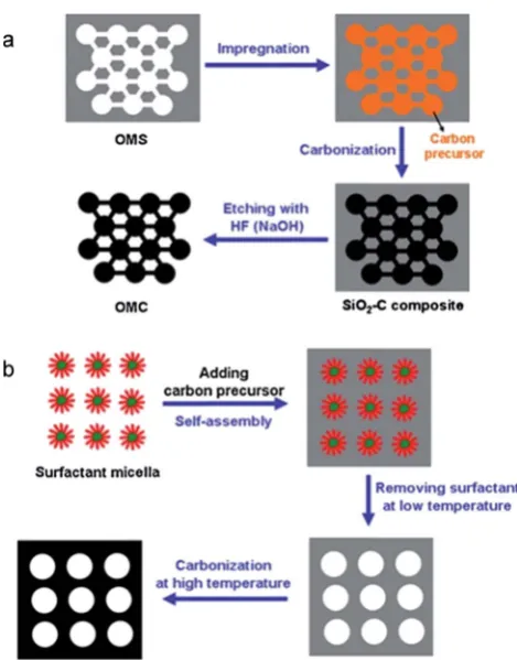
The hard-template (e.g.SBA-15, MCM-41 and silica colloid) and so-template (e.g.amphiphilic surfactants and triblock co-polymers) approaches are two widely used synthesis methods of OMCs. In the hard-template method, pores in OMS are mixed with a carbon source (e.g. sucrose, resorcinol and formalde-hyde). Then the carbonization is completed by pyrolysis at high temperature, followed by removing the silica template to obtain the OMCs. In the so-template method, a carbon precursor (organic monomers) is polymerized with the self-assembly of a surfactant in a liquid to form a carbon-surfactant composite. Aer removing the surfactant, carbonization will be carried out by pyrolysis at high temperature. Schematic diagrams of the two synthesis methods are shown in Fig. 1.56Both methods to make
carbon based mesoporous supporting materials require a pyrolysis process (normally at 900–1000 C under a N2
atmosphere) to graphitize the carbon precursor. Mesoporous carbon nanoparticles can also be prepared with glucose as the carbon precursor partially carbonized at 180C for 4 h, followed by functionalization with an amine-terminated ionic liquid.57
Finally, metal ions are reduced and deposited on OMCs to obtain MSMMs.
Until now, different kinds of MSMMs have been successfully synthesized. In Ahnet al.'s experiment, colloidal silica was used as the template and sucrose was used as the carbon source to obtain 50 wt% Pt/OMCs.58Half of the pores of OMCs (5 nm
diameter) are uniformly occupied by Pt nanoparticles (2.5 nm particle size) or are lost during Pt/OMC preparation. In addition to the enhanced metal-accommodation ability, mesoporous carbon also leads to better mass transport according to the polarization plots and electrochemical impedance spectroscopy (EIS) results.59Heet al.have investigated the cyclic
voltammo-grams (CVs) of methanol oxidation on commercial Pt/C (E-TEK) and Pt/mesoporous carbon nanoparticles (Pt/MCNPs).57In the
forward scan, the maximum current density of Pt/MCNPs is 2.3 times higher than that of the E-TEK Pt/C catalyst. Leeet al.used SBA-15 as the template to prepare OMCs supported Pt–Ru for methanol oxidation, achieving a specic surface area about 900 m2g1and pore size about 4 nm.60The specic surface area of
OMCs is much larger than that of commercial carbon supports (about 240 m2g1, Vulcan XC-72R).61TEM images show that the
Pt–Ru nanoparticles are uniformly deposited on OMCs and the particle sizes are limited to 4 nm. They further prepared
Fig. 1 Schematic diagrams of (a) hard template and (b) soft template methods to prepare mesoporous carbon. Reproduced with permis-sion from ref. 56. Copyright 2014, Elsevier.
Open Access Article. Published on 09 September 2016. Downloaded on 04/11/2016 12:39:22.
This article is licensed under a
[image:4.595.309.544.45.345.2]O-doped OMCs by H2O2treatment to improve the activity.
N-doped mesoporous carbons are also developed by using
nitrogen-containing carbon precursors such as
poly-acrylonitrile, polypyrrole and polyaniline.62–65 Zhang et al.
developed a honeycomb-like mesoporous N-doped carbon supported Pt catalyst for methanol oxidation.66Cyclic
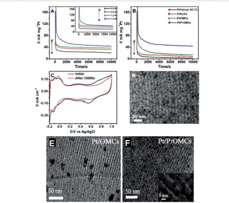
voltam-mogram measurements indicate that the peak current density of the N-doped carbon catalyst is 1.4 times higher than that of the carbon catalyst without N doping. The addition of nitrogen element not only has an intense anchoring effect on Pt nano-particles, but also enhances the electrical conductivity. The doping of P heteroatom inhibits the aggregation of metal particles and leads to a uniform distribution on mesoporous carbons, clearly presented in the TEM pictures in Fig. 2E, in contrast with Fig. 2F.67The Pt supported on phosphorus doped
OMCs (Pt/P7OMCs) demonstrates a much higher current
density than Pt/OMCs, Pt/Vulcan XC-72 and PtRu/XC in chro-noamperometry (see Fig. 2B). Pt/P7OMCs have a relatively stable
electrochemical activity and better CO-tolerance towards methanol oxidation. One reason may be the increase of oxygen-containing functional groups aer P doping, which promote CO-tolerance and enhance the stability. It can be found from Fig. 2C that ECSA (90.76.1 m2g1) aer a 10 000 s stability
test is only a little bit lower than the original value (96.3 7.3 m2 g1), and from Fig. 2D that Pt nanoparticles are not obviously aggregated aer 10 000 s. Moreover, mesoporous carbons incorporated with other compounds, such as ceria, carbon nanotubes, tungsten carbide and tin oxide are also prepared.68–71 Ceramic materials such as ceria and tungsten
carbide were observed to have a stabilization effect on Pt during the long time test.68,69Stability tests indicate that the
electro-chemically active surface of Pt/mesoporous carbon–ceria
Fig. 2 (A) Chronoamperometry curves of Pt/P7OMCs at different oxidation voltages: (a) 0.5, (b) 0.6, (c) 0.8, (d) 0.7 V (inset: with different
concentrations of methanol at 0.7 V) in a solution of 0.5 M H2SO4+ 1.0 M CH3OH. (B) Chronoamperometry curves of Pt/Vulcan XC-72, PtRu/XC,
Pt/OMCs and Pt/P7OMCs recorded at 0.7 V. Scan rate: 50 mV s1. (C) CVs of Pt/P7OMCs in 0.5 M H2SO4before and after 10 000 s stability test.
TEM image of (D) Pt/P7OMCs after 10 000 s stability test; (E) Pt/OMCs and (F) Pt/P7OMCs. Reproduced with permission from ref. 67. Copyright
2014, Elsevier.
Open Access Article. Published on 09 September 2016. Downloaded on 04/11/2016 12:39:22.
This article is licensed under a
[image:5.595.56.529.254.672.2]reduces by 45% aer accelerated degradation of 2000 min, in comparison to 70% of conventional Pt/C.69Tin oxide is also
regarded to enhance the ethanol oxidation on Pt by effectively splitting the C–C bonds in ethanol.71Pt on carbon nanotubes
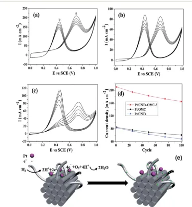
doped OMCs (Pt/CNTs–OMC) prepared by Zhanget al.exhibit about twice higher current density in methanol oxidation than Pt/CNTs and Pt/OMC (see Fig. 3).70This is because the doping of
CNTs forms a unique structure of CNTs–OMC nanocomposites, which is conductive to electron transfer across the OMC parti-cles and results in lowering of the interfacial resistance, illus-trated in Fig. 3e. Accordingly, the conductivity of OMC is only 4.3 S m1, and it rises to 26.4 S m1aer doping CNTs. The ECSAs of Pt/OMCs, Pt/CNTs and Pt/CNTs–OMCs are 57.8, 80.4 and 113.4 m2g1, respectively. In brief, all these doped meso-porous carbons present further improvement of activity and durability of Pt-based catalysts for oxidation reaction in comparison with non-doped mesoporous carbon which are big advantages for fuel cell applications.
Besides carbon-based mesoporous supporting materials, non-carbon mesoporous supporting materials (e.g. CrN, TiN, SnO2–Sb) have also been developed for Pt. These supports have
a large surface area due to the porous structure. Gurrolaet al. claim that aer 100 cycles of CVs in acid medium, ECSA of Pt/ Sb–SnO2decreases less than 10%.72In contrast, ECSA of Pt/C
decreases signicantly attributing to the oxidation of carbon supports. In addition, metal nitride is a better choice for non-carbon supporting materials, as it not only exhibits long-time stability and faster oxidation of CO, but also has high electrical conductivity. Mesoporous TiN is prepared by Yang et al. via a solid–solid phase separation method.73 This material is
formed by heating Zn2TiO4in ammonia gas without a template.
Mesoporous TiN demonstrates a high conductivity of 395 S cm1at 35 bar and good electrochemical stability. Accounting to the CV tests of methanol oxidation, the peak current density of Pt/TiN is 1.5 times higher than that of Pt/C. Yanget al.also prepared mesoporous CrN with a high conductivity of 54 S cm1
Fig. 3 Long-term stability of (a) Pt/CNTs–OMC, (b) Pt/OMC and (c) Pt/CNTs in 1.0 mol L1H
2SO4+ 2.0 mol L1CH3OH with a scan rate of 50
mV s1for 100 cycles and (d) the current density tendency of Pt/CNTs–OMC, Pt/OMC and Pt/CNTs in the forward scan with increasing cycle
number. (e) Schematic of electron transport in Pt/CNTs–OMC. Reproduced from ref. 70 with permission from the Royal Society of Chemistry.
Open Access Article. Published on 09 September 2016. Downloaded on 04/11/2016 12:39:22.
This article is licensed under a
[image:6.595.96.483.273.689.2]by ammonolysis of K2Cr2O7.74The pore size ranges from 10 to
20 nm, and some microporosity is observed. CrN is electro-chemically stable at acidic conditions up to 1.2 V, where carbon materials tend to corrode. When used as a Pt supporting material (Pt/CrN) for methanol oxidation, the synergistic effect of Pt and CrN allows faster CO oxidation. The peak current density is 195 mA mgPt1for Pt/CrN and 145 mA mgPt1for Pt/
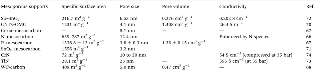
C. Pt/CrN shows higher electrochemical activity and a slower deterioration rate than Pt/C. Recently developed mesoporous supports are summarized in Table 1.
The recently reported MMECs and MSMMs for fuel cell anodes achieved enhanced specic mass activity and durability which are superior to those of commercial Pt/C catalysts. MMECs can be prepared in a facile way at room temperature, avoiding the origin of high cost of high-temperature pyrolysis during the MSMM synthesis. In addition, MMECs can also be directly grown on an electrode surface under good contact conditions by the electrodeposition method,34,38,42without the
use of costly ionomers to immobilize catalysts onto the elec-trode surface. The nanostructure, particle size, pore size and elemental composition of MMECs and MSMMs can be designed by choosing the templates and reaction conditions during the synthesis, in order to obtain optimal performance. This provides a promising method for the generation of high-performance and cost-effective metal catalysts for fuel cells with stable performance.
3.
Use of mesoporous materials in
cathode catalysts
The cathode reaction of the oxygen reduction reaction (ORR) is the rate-determining process in PEMFCs, thus there are many investigations into ORR catalysts. The ORR has different reac-tion routines in acidic and alkaline PEMFCs:75
Acidic conditions:
O2+ 4H++ 4e/2H2O (4epathway) (1)
O2+ 2H++ 2e/H2O2(2epathway) (2)
H2O2+ 2H++ 2e/2H2O (3)
Alkaline conditions:
O2+ 2H2O + 4e/4OH(4epathway) (4)
O2+ H2O + 2e/HO2+ OH(2epathway) (5)
H2O + HO2+ 2e/3OH (6)
Oxygen can be directly reduced to H2O or OH viaa 4e
pathway, or incompletely reduced to H2O2 or HO2viaa 2e
pathway. In proton exchange membrane fuel cells, H+is trans-ported from the anode to cathode to further react with O2,
forming H2O or H2O2. The anion exchange membrane based
PEMFCs produce OHas charge carriers via ORR to provide alkaline conditions. This will allow the use of nonprecious transition metals based mesoporous catalysts for fuel cells.
3.1 Mesoporous cathode electrocatalysts for acidic PEMFCs
Platinum based metals with carbon supports have good cata-lytic behaviour toward ORR. Nevertheless, the high cost and activity degradation due to agglomeration of platinum nano-particles, corrosion of the carbon supports and anode fuel crossover still exist as a bottleneck for wide commercial appli-cation. Accordingly, numerous efforts have been made to improve the catalyst performance. Similar to anode catalysts, mesoporous carbon is used as a support for Pt. Liu et al. prepared mesoporous carbon supported Pt, which exhibits higher mass specic kinetic current density than XC-72 carbon supported Pt.76The durability is also improved, as the
electro-chemical surface area of Pt/mesoporous carbon decreases from 24.5 cm2 mgPt1 to 20.6 cm2 mgPt1 and that of Pt/XC-72
decreases from 21.8 cm2mgPt1to 11.1 cm2mgPt1under the
same conditions. Besides, mesoporous carbon supported Pt can inhibit the formation of H2O2 with a yield of 0.25% in ORR,
lower than the yield of 1.25% from Pt/C.77
Modied mesoporous carbons and mesoporous metal
nitride supported Pt exhibit much more remarkable improve-ment. Youet al.synthesized OMC–SiC composites as a support for Pt by a controlled carbothermal reduction process to utilize both the ordered mesopores of OMC and the high electro-chemical stability of the SiC materials.78 The ORR current
density using Pt/OMC–SiC shows negligible change (0.16%)
aer 1000 cycles, while the ORR current density using
[image:7.595.41.555.62.183.2]commercial Pt/C decreases by 33.4%. The improvement is attributed to a strong interaction of platinum and Si atom on
Table 1 A summary of properties of various mesoporous supports
Mesoporous supports Specic surface area Pore size Pore volume Conductivity Ref.
Sb–SnO2 216.7 m2g1 6.53 nm 0.276 cm3g1 0.202 S cm1 72
CNTs–OMC 1231 m2g1 4.1 nm 1.408 cm3g1 26.4 S m1 70
Ceria–mesocarbon — 5.1 nm — — 67
N–mesocarbon 639–787 m2g1 12.4 nm — Enhanced by N species 66
P–mesocarbon 1338.813 m2g1 3.80.3 nm 1.360.15 cm3g1 — 67
SnO2–mesocarbon 1556 m2g1 3.2 nm — — 71
CrN 72 m2g1 10 to 20 nm — 54 S cm1(compressed at 35 bar) 74
TiN 28.1 m2g1 25 nm — 395 S cm1(at 35 bar) 73
WC/carbon 409 m2g1 5.0 nm 0.47 cm3g1 — 68
Open Access Article. Published on 09 September 2016. Downloaded on 04/11/2016 12:39:22.
This article is licensed under a
the surface of carbon frameworks, which makes the catalyst more electrochemically stable. In addition, zirconia with the treatment of a sulfonated ionomer has been used to modify mesoporous carbon supports to form zirconia/ionomer/mes-oporous carbon.79The mass ORR activity increases from 51
mA mgPt1 to 74 mA mgPt1 when the ionomer is used to
improve the availability of protons and enhance O2solubility.
Yanget al.tested non-carbon mesoporous CrN supported Pt as a catalyst for ORR.80 The specic surface area of Pt/CrN is
68.5 0.1 m2 g1. Kinetic current density obtained from polarization curves at 0.9 V is 9.1 mA mgPt1for Pt/CrN and
5 mA mgPt1for commercial Pt/C, respectively. Another
non-carbon mesoporous support for oxygen reduction reaction is TiNbN with a pore size of 30–50 nm.81Its electrical
conduc-tivity reaches 3.9 S cm1, which is about 2.5 times higher than that of Vulcan XC-72 carbon black (1.5 S cm1) under the same measurement conditions. Though its specic surface area is 45 m2 g1, which is smaller than that of the mesoporous carbon support, Pt/TiNbN still exhibits larger kinetic current density (256 mA mgPt1) than Pt/C (142 mA mgPt1) at 0.9 V.
The activity loss of Pt/TiNbN and Pt/C aer 5000 cycles is 19.2% and 29.4% respectively, indicating that the stability is improved. In addition, TiNbN is stable both in acidic and alkaline solution.
Transition metal catalysts with mesoporous carbon have been proved to be better than those with carbon black attrib-uting to the increased surface area.82–86 According to Liang's
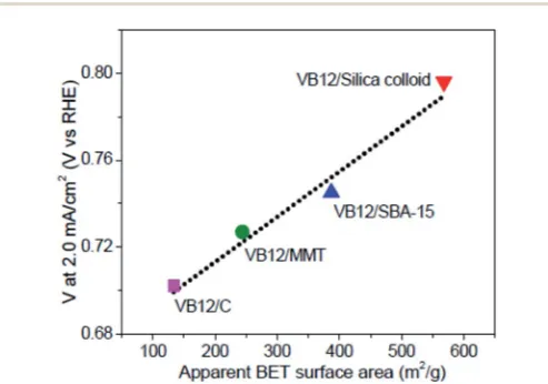
work, a series of mesoporous carbon supported Co (C–N–Co) catalysts are prepared using different templates (silica colloid, ordered mesoporous silica SBA-15, or montmorillonite).85The
ORR activity is found to be proportional to the specic surface area, as shown in Fig. 4. As a result, mesoporous carbon sup-ported catalysts (VB12/MMT, VB12/SBA-15, VB12/silica colloid) perform better than carbon black supported catalysts (VB12/C) due to the increase in surface area. Liuet al.prepared stable and methanol-tolerant ORR catalysts,i.e.Fe carbide supported on N-doped carbon, with a high specic area (705 m2 g1) and
kinetic limiting current density (18.35 mA cm2at 0.7 V).87
3.2 Mesoporous electrocatalysts for alkaline membrane fuel cells
In alkaline PEMFCs, transition metals such as Fe and Co based compounds supported on mesoporous carbons are also inves-tigated as ORR catalysts in order to avoid the use of noble metals.88–92Cobalt oxide and cobalt sulde supported on
mes-oporous carbon or heteroatom doped carbon possess compa-rable or even higher catalytic activity than commercial Pt/C toward ORR.93–96In addition, Co based catalysts are remarkably
methanol-tolerant and more stable than Pt/C. For example, in chronoamperometric tests, when the current of Pt/C decreased by 26%, the current of CoS/N,S-codoped porous carbon reduced by only 8% under the same conditions.95 A Ni-doped Co
3O4
nanowire array (nNi/nCo ¼ 1 : 9) with a mesoporous structure
was used for ORR by Tonget al.recently.97This mesoporous Ni–
Co3O4has a large pore volume of 0.23 cm3g1with the pore size
ranging from 4 to 15 nm, leading to a large surface area of 70.3 m2g1. It exhibits more positive half-wave potential (E
1/2¼
0.86 V) and higher diffusion-limiting current density (JL¼about
5.76 mA cm2) than Co3O4(E1/2¼0.6 V,JL¼1.32 mA cm2) and
Pt/C (E1/2¼0.85 V,JL¼ 5.42 mA cm2) catalysts. It is almost
insensitive to methanol and CO, and much more stable than Pt/ C in accelerated ORR measurements. Some studies reported that Fe based mesoporous catalysts possess high catalytic activity comparable with commercial Pt/C, long-time stability and methanol tolerance.98,99 The addition of Fe has been
observed to greatly improve the ORR activity of mesoporous carbon with N doping due to the high density of surface active sites.98,99 When a trace amount of Fe (0.2 at%) is added, the
calculated kinetic current density of Fe–N–C catalyst increases from about 6 mA cm2(N–C catalyst) to 32.26 mA cm2, which is higher than that of Pt/C (30.56 mA cm2).100 It was also
noticed that the electron transfer number of ORR changes from 2.61 to 4.04. However, Yanget al.found that the role of Fe was to produce more active N sites during the catalyst preparation, and the physical presence of Fe in N-doped carbon was not neces-sary to enhance the ORR activity.101The activity sites of Fe–N–C
need to be further investigated. Until now, great improvement in the use of nonprecious metals based ORR catalysts has been made for both acidic and alkaline PEMFCs, as listed in Table 2, in order to reduce the cost and enhance the performance.
3.3 Metal-free mesoporous electrocatalysts
The use of metal based catalysts brings concerns about toxic metal pollution, irreplaceable or rare metal resources and hard-degraded substances. The crossover of anode fuels is one of the challenges in fuel cells, and metal based catalysts are active toward both anode and cathode fuels. As a result, fuel cell efficiency will be reduced owing to the undesirable oxidation reaction at the cathode. Carbon materials are renewable and easy to handle, and are tolerant to anode fuels. They are promising materials for cathode catalysts to reach high effi -ciency and reduce the cost. Furthermore, heteroatoms have different electronegativity and size from carbon atoms, and they can change the charge distribution and electronic properties of pure carbon materials.26,75 Tailoring carbon materials by the
Fig. 4 The correlation between catalyst activity and apparent BET surface areas of the C–N–Co catalysts. Reproduced with permission from ref. 85. Copyright 2013, American Chemical Society.
Open Access Article. Published on 09 September 2016. Downloaded on 04/11/2016 12:39:22.
This article is licensed under a
[image:8.595.43.290.518.691.2]introduction of heteroatoms to obtain metal-free catalysts with ideal ORR activity is a hot issue nowadays. In recent years, nitrogen-doped carbon with N-containing polymers, ammonia, as well as nitrogen gas as the nitrogen source or the source of both nitrogen and carbon has been developed, which possesses good ORR activity.103–108 Further developments on the
combi-nation of mesoporous carbon materials with heteroatom doping make metal-free catalysts a potential substitution for the Pt/C catalyst.
In a recent study, the SBA-15 template was impregnated with pyrrole as both the carbon and nitrogen source via vapor-ization–capillary condensation in a vacuum container, and then
formation of the nitrogen-doped OMC aer polymerization and etching.109The ORR current density at 0.9 V reached 0.07, 0.09
and 0.12 mA cm2 when the pyrolysis temperature was at
800 C, 900 C and 1000 C respectively. Furthermore it was found that nitrogen-activated carbon (C–N) is the active site for the ORR because current density increases with the C–N frac-tion. Zhanget al.developed a simple template-free method to fabricate nitrogen-doped porous carbon foam from melamine– formaldehyde foam by a two-step pyrolysis process: heating at 300C in air and then at 1000C in a N2atmosphere.110This
[image:9.595.44.546.62.565.2]carbon foam (4.3 at% N content) has a small pore size below 5 nm and gives rise to a high specic surface area of 980 m2g1.
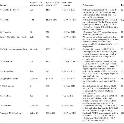
Table 2 Selected ORR catalysts composed of nonprecious transition metals with mesoporous carbon as a supporting material
Catalyst
Centred pore diameter (nm)
Specic surface
area (m2g1)
ORR onset
potential Performance Ref.
Fe–N/OMC (hollow-core) 3.5 1187 0.89 Vvs.RHE ORR current densities at 0.8 Vvs.RHE
are0.04 mA cm2for Fe–N/commercial
carbon (Ketjen black CJ600), and1.0
mA cm2for Fe–N/OMC
82
Fe–N/OMC 22 1138 to 1338 0.8 Vvs.RHE ORR current densities at 0.55 Vvs.RHE
are1.1 mA cm2for Fe–N/commercial
carbon (Black Pearl 2000), and1.5 to
3.0 mA cm2for Fe–N/OMC (depending
on the pore diameter)
83,84
Co–N–carbon 12 572 0.87vs.RHE 4.5 mA cm2at 0.3 V, better than carbon
black supported Co–N
85
CoFe–N–OMC (Co : Fe¼1 : 3) 2.4 670 0.7 Vvs.RHE When used as cathode catalysts in fuel
cell tests, at a cell voltage of 0.3 V, current density of PAIN/CoFe/OMC and
commercial Pt/C is 0.89 and 1.07 A cm2,
respectively
86
Co3O4/N–mesoporous graphene 20 to 40 1599 0.93 Vvs.RHE Compared to commercial Pt/C, it has
a more positive onset potential, higher current density and improved stability from the prevention of nanoparticle agglomeration
93
CoO/N–carbon 3.3 1390 0.06 Vvs.Ag/AgCl Kinetic-limited current density reaches
22.29 mA cm2at0.4 V, higher than
that of commercial Pt/C (21.32 mA cm2);
largely improved methanol tolerance
94
CoS/N,S–carbon N/A 248 0.92 Vvs.RHE ORR current density reaches4.50 mA
cm2at 0.45 Vvs.RHE, largely improved
methanol tolerance
95
CoS2/graphene oxide 2.5 to 3.5 10 to 19 0.97 Vvs.RHE ORR potential at3 mA cm2is 0.76 V
for CoS2/graphene oxide and 0.86 V for Pt/C
96
Fe3C@N–carbon 2 705 0.92vs.RHE Kinetic limiting current density (18.35
mA cm2, at 0.7 V) was close to that of
commercial Pt/C catalyst (19.25 mA
cm2, at 0.7 V)
87
Fe–N/carbon 6.6 56 0.92vs.RHE ORR activity is comparable to Pt/C both
in acidic and alkaline media, high density of surface active sites, while its
specic surface area is not so high
98
Fe–N–carbon 3.0 to 5.5 236 0.95vs.RHE Kinetic current density is 7.40 mA cm2
at 0.82 V, higher than that for Pt/C (6.30
mA cm2at 0.82 V), high stability
99
Fe/carbon–N, Co/carbon–N 3.4 to 4.9 700 to 860 0.8 Vvs.RHE Single cell PEMFC current density at 0.6 V
vs.RHE:0.1 A cm2for Fe/OMC–N;
0.06 A cm2for Co/OMC–N;0.3 A
cm2for commercial Pt/C
102
Open Access Article. Published on 09 September 2016. Downloaded on 04/11/2016 12:39:22.
This article is licensed under a
Rotating disk electrode (RDE) voltammograms are used to investigate the ORR pathway of this carbon foam. It reveals that the average electron transfer number is about 3.6 with little hydrogen peroxide generation. The ORR activity of carbon foam is slightly lower than that of Pt/C, but the methanol-tolerance is largely improved. Nanoporous carbon nanocables with carbon nanotubes as the core and N-doped carbon as the shell have been prepared by Jiang et al.111 This core–shell catalyst has
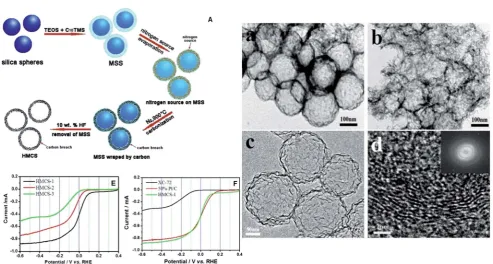
a specic surface area of 413 m2g1and pore diameter range from 1.7 to 4 nm. It demonstrates much higher ORR activity than the catalyst with a core or shell only. It achieves a four-electron transfer in ORR with high catalytic activity comparable with Pt/C and remarkable methanol tolerance. Nitrogen-doped hollow mesoporous carbon spheres (HMCSs) were also prepared based on mesoporous silica spheres (MSSs) as shown in Fig. 5.112MSSs are initially formed from
tetraethylorthosili-cate (TEOS) and trimethoxy(octadecyl) silane (C18TMS), then
HMCSs are prepared aer carbonization with the addition of nitrogen and carbon sources and HF washing. The nitrogen sources for HMCS-1 and HMCS-2 are glycine and lysine, respectively, and glucose for HMCS-3 (no nitrogen doping). Aer forming a hollow structure, the specic surface area increases from 335 m2 g1 (MSSs) to 451 m2 g1 (HMCSs). Among the three prepared metal free catalysts toward ORR, HMCS-1 is the most active one, which displays comparable although inferior ORR activity to the commercial Pt/C catalyst (see Fig. 5E and F). HMCSs show excellent methanol tolerance as they are inactive toward methanol, so they are a promising catalyst to replace Pt catalysts and achieve high efficiency. Moreover, another route has been reported to prepare hollow
nitrogen-doped carbon (HNC) as a simple, environmental friendly, economic and template-free synthesis method, as shown in Fig. 6.113Aniline monomer was polymerized with the
addition of K3[Fe(CN)6] in an ice bath (<5C) for 24 h, followed
by washing and carbonization to form a hollow and porous structure. Trace Fe (0.13 at%) was lein HNC, with C, O, N contents of 86.55, 11.87, and 1.95 at%. Fig. 6a and b demon-strate that HNC is close to commercial Pt/C in ORR activity. In addition, the HNC has advantages of better methanol crossover resistance and long-term durability in alkaline medium. This feature is excellent for methanol fuelled alkaline membrane fuel cells.
Dual elements doped mesoporous carbon was also prepared as an ORR catalyst, such as B-, N-doped carbon nanobers, S-, N-doped mesoporous carbon, and O-, N-doped mesoporous carbon. Mesoporous carbon doped with N and O was fabricated by the thermal treatment of PANI/SBA-15 and silica etching.64
The heating temperature (600C to 900C) could affect the N and O contents in mesoporous carbon. Nitrogen atoms were observed to decrease with increase in temperature. In contrast, O atoms would increase as the O is introduced from the mes-oporous silica driven by the high temperature. The current density of ORR achieved from mesoporous N-, O-carbon synthesized at a pyrolysis temperature of 800C is larger than that of Pt/C. Qi Shiet al.prepared two kinds of B, N-codoped mesoporous carbon nanobers, namely BNCf-N and BNCf
-NA.114 BNC
f-N is pyrolysed with a mixture of boric acid/urea
under N2, and BNCf-NA is further treated under NH3. The B–N–
C sites can enhance the ORR activity and demonstrate the synergistic effect of B, N-codoping. Raman and XPS spectra
Fig. 5 (A) Schematic illustration of the formation of HMCSs; TEM micrographs of HMCS-1 (a) and HMCS-2 (b); HRTEM micrographs (c and d) and SAED (inset in d) of HMCS-1; ORR polarization curves of HMCSs (E) and Pt/C (F) in O2saturated 0.1 M KOH solution, sweep rate: 10 mV s1,
rotation speed: 1600 rpm. Reproduced with permission from ref. 112. Copyright 2014, Elsevier.
Open Access Article. Published on 09 September 2016. Downloaded on 04/11/2016 12:39:22.
This article is licensed under a
[image:10.595.51.545.426.690.2]show that the content of defect sites is enhanced aer NH3
activation. The relative amount of pyridinic-N, which is favourable for ORR, increased from 13 (BNCf-N) to 41 at%
(BNCf-NA) aer NH3activation, as shown in Fig. 7. The specic
surface area increased from 24.7 (BNCf-N) to 306.3 m2 g1
(BNCf-NA) aer NH3activation. Compared with commercial Pt/
C catalysts, the metal free BNCf-NA catalyst shows high
elec-trocatalytic efficiency, much better stability and methanol tolerance thus a promising alternative to the Pt/C ORR catalyst.
To date, S-, N-doped porous carbon materials have been re-ported with different N and S sources, as shown in Table 3. Normally N and S co-doped carbon catalysts present a larger electron transfer number compared to sole N or S doped carbon catalysts, leading to high efficiency of ORR.115–117Sulphur atoms
bonding with carbon have a thiophene-like structure, which has been proved to improve the catalysts with sole nitrogen doping due to the synergistic effects originating from S and N atoms.116–118 For example, S-, N-doped porous carbon foam
Fig. 6 Schematic representation of the synthesis of hollow nitrogen-doped carbon; (a) CV curves of HNC and commercial Pt/C catalysts in 0.1 M KOH at a sweep rate of 50 mV s1. (b) LSV curves of HNC and commercial Pt/C catalysts in O2saturated 0.1 M KOH at a sweep rate of 10 mV s1
and 1600 rpm rotating speed. Reproduced with permission from ref. 113. Copyright 2015, Elsevier.
Fig. 7 B 1s and N 1s XPS spectra of (a and b) BNCf-N and (c and d) BNCf-NA. Reproduced with permission from ref. 114. Copyright 2015, Elsevier.
Open Access Article. Published on 09 September 2016. Downloaded on 04/11/2016 12:39:22.
This article is licensed under a
[image:11.595.132.465.50.260.2] [image:11.595.44.535.445.709.2]exhibits an ORR onset potential close to that of Pt/C, and its current density is higher with a limited-kinetic current density of 11.69 mA cm2 at 0.40 V.119 Rotating-disk voltammetry
measurements show that the electron transfer number is 3.96, indicating a high-efficiency four-electron process with negli-gible formation of H2O2.
Gao et al. reported N-, S-, and P-tridoped porous carbon fabricated from the pyrolysis of worst weed (Eclipta prostrata).122
Heteroatoms were directly introduced from the natural compounds of worst weed. The as-prepared tri-doped carbon consists of mesopores with diameter from 5 to 30 nm and a small number of macropores with diameter from 100 to 150 nm. The pore volume and specic surface area reach 0.2676 cm3 g1and 378.5 m2g1, respectively. This (N, S, P)-doped carbon achieves higher catalytic activity and better durability toward four-electron ORR in comparison with the Pt/C catalyst.
Pyrolysis temperature is a vital factor in the synthesis of heteroatoms doped mesoporous carbon, which can largely affect the catalytic activity as well as the number of electrons transferred for ORR. The optimal pyrolysis temperature is around 900C according to the reported studies, and it may vary because of the different carbon and heteroatom precursors used.64,109,111,115–117,119,121If the pyrolysis temperature is too low,
the carbon sheath will not be adequately graphitized, thus the as-prepared mesoporous carbon will be of poor electrical conductivity. If the pyrolysis temperature is too high, active sites in the as-prepared mesoporous carbon will decrease due to the low heteroatom doping level (density). Besides, the specic surface area and pore volume of mesoporous carbon are also inuenced by the pyrolysis temperature. For these reasons, optimal preparation conditions need to be investigated in order to make heteroatom doped mesoporous carbon a potential substitute for the commercial Pt/C catalyst with enhanced ORR activity, complete reduction product, long stability and meth-anol tolerance.
4.
Fuel cell performance using
electrocatalysts with a mesoporous
structure
[image:12.595.72.261.39.723.2]Although many studies reported the superior performance of mesoporous catalysts toward anode and cathode reactions characterized by electrochemical measurements in three-elec-trode systems, it was still required to be further veried by practical fuel cell performance. The three-electrode measure-ments are performed in bulk electrolytes with catalysts in direct contact with fuels. In fuel cell electrodes, liquid or gas fuels need to pass through the diffusion layer to reach the catalyst layer. As a fuel cell is a more complicated system, many factors such as MEA fabrication (Naon loading, gas diffusion layer, press process,etc.) and operation conditions (temperature,ow rate, humidity,etc.), barring its catalyst properties, will affect its current density, which probably diminish the superiority of mesoporous catalysts. For example, when Pt/mesoporous carbon (Pt/MC) is assembled at the cathode in a H2/O2fuel cell,
the power density is higher than that of the Pt/C cathode at
Table 3 Rece ntly report ed N-, S-co -doped me sopor ous carbo n catal ysts for ORR Cataly st Precurs or (C, N, S) Syn thesis meth od and pyro lysis tem peratu re Speci c surfac e area (m 2 g 1 ) Content of S, N atom s Ref. N,S – mesoporou s carbon Thiophen e and py rimi dine Mesop orous silica tem plate an d chemi cal vapour deposition, 700 C 1100 N: 4.7 at% and S: 0.68 at% 115 N,S – mesoporou s carbon foams Aniline, Na 2 S2 O3 an d (NH 4 )2 S2 O8 Poly meriza tion of anili ne (shell) on the surfac e o f sulphur spheres (core) an d pyro lysis, 1000 C 133.56 N: 0.58 at% and S: 1.0 at% 116 N,S – mesoporou s graphe ne Melamine and benzy l disul de Mo di ed Humme rs method , colloid al silica template and py rolysis, 900 C 157 – 220 N: 4.5 at% and S: 2.0 at% 117 N,S – mesoporou s carbon /graph ene nan osheet s Cysteine Mesop orous silica/g raphen e tem plate and py rolysis , 900 C 281 N: 2.97 wt%; S: 0.89 wt% 118 N,S – porous carbon foams Thiou rea Mesop orous silica tem plate an d pyro lysis, 1000 C 394 N: 6.53 wt%; S: 2.88 wt% 119 N,S – mesoporou s carbon Phenothi azine (or indigo carmi ne) Mesop orous silica tem plate an d pyro lysis, 750 C 855 (4 09) N: 4.51 (6.38) wt%; S: 4.12 (6.38) w t% 120 N,S – porous carbon 1-Allyl-2-thiou rea Silic a n a nosph eres template and pyro lysis, 400 – 1000 C( 9 0 0 C is opti mal) 56.9 to 860.4 N/C (% ): 2.5 – 26; S/C (%) : 0.7 – 3.1 121
Open Access Article. Published on 09 September 2016. Downloaded on 04/11/2016 12:39:22.
This article is licensed under a
60C.123However, the power densities become similar when the
operation temperature is 30C. Ahnet al.found that Pt particles in Pt/MC could deposit on two or more ordered carbon nano-rods to share the Naon ionomer and electrolyte, thus less ionomer loading was required. The optimal Naon loading at the cathode for Pt/MC (10 wt%) is found to be lower than that for Pt/C (20 and 30 wt%).58 In direct methanol fuel cells
(DMFCs) at 80 C, Pt/MC assembled in the anode showed
a maximum power density 8% higher than that of Pt/C, but Pt/ MC assembled in the cathode even showed slightly lower maximum power density than Pt/C, and its best Naon loading was 35%.77Theow rate of fuels also has different effects on Pt/
MC and Pt/C. Recently Brunoet al.prepared Pt/MC with 5.3 nm Pt particle size, which is 25% smaller than that of Pt/C (Vulcan carbon).124When Pt/MC and Pt/C are used as cathode catalysts,
the maximum power density of DMFCs reaches 30 mW cm2
and 16 mW cm2respectively when air was used at the cathode. They found that although mesoporous catalysts could reduce the mass transport losses promoting the water transportation, they would also promote the drying out of the MEA at highow rates. As shown in Fig. 8A, the highest power is achieved at 100 sccm airow, and the power will reduce as the airow increases to 150 sccm when using Pt/MC as the cathode catalyst. In
contrast, in Fig. 8B, the power is observed to keep increasing with airow up to 150 sccm when using Pt/C. Thus it is of vital importance for practical application of mesoporous catalysts to optimize MEA preparation and the operation conditions of polymer electrolyte membrane fuel cells.
In most reported studies, better results have been observed with mesoporous catalysts in fuel cell tests due to their merits as shown in Table 4. The Pt or Pt-alloy particles (3 nm) can only be dispersed on the surface of microporous supports (<2 nm in pore size), which aggregate easily and give rise to low ECSA. In addition, the Naon ionomer fails to enter pores with diameter smaller than 20 nm, showing poor contact between the metal nanoparticles and the Naon ionomer.125,126 In contrast, the
adequate pore size of mesoporous supports leads to more Pt dispersion and fuels accessible in mesopores.126Pt particles in
the mesopores could share the Naon ionomer and fuels, thus less ionomer loading was required.58 The H
2O produced by
electrochemical reactions can easily transfer from the catalyst layer to the gas diffusion layer with less space occupied by the ionomer. Thus the mesoporous structure is favourable for mass transport in the catalyst layer.126,127 On the anode side, when
assembled with PtRu/C, the maximum power density of DMFC reaches 17 W gPt1(34 mW cm2) and 26 W gPt1(61 mW cm2)
[image:13.595.49.550.343.535.2]Fig. 8 Polarization and power curves at different airflows for (A) Pt/mesoporous carbon and (B) Pt/Vulcan carbon at 60C and 1 M methanol as an anode fuel. Reproduced with permission from ref. 124. Copyright 2015, Elsevier.
Table 4 Comparisons between mesoporous catalysts and traditional carbon supported Pt (Pt alloys) applied in fuel cell electrodes
Mesoporous catalysts Traditional carbon supported Pt (Pt alloys)
Pt dispersion Uniform with high specic area Easy to aggregate
Mass transport of fuels Good access to fuels due to adequate pore sizes
and volumes
Pore size too small to obtain adequate fuels,
pore space tends to belled with H2O to slow
down mass transport
MEA preparation Applicable to alkaline and acidic membranes,
less ionomer loading required
Applicable to alkaline and acidic membranes,
normally 20–40 wt% of ionomer loading
Durability Enhanced thermal, chemical and mechanical
stability, tolerant to methanol crossover (heteroatom doped carbon)
Degeneration of carbon black, not tolerant to methanol crossover
Price Cost-effective, noble-metal-free High price due to the use of noble metals
Open Access Article. Published on 09 September 2016. Downloaded on 04/11/2016 12:39:22.
This article is licensed under a
[image:13.595.45.548.602.733.2]at 30 C and 60 C respectively.59 It increases to 31 W g
Pt1
(40 mW cm2) at 30C and 45 W gPt1(67 mW cm2) at 60C
when assembled with PtRu/MC, attributing to the fast oxidation rate and enhanced mass transport of methanol with meso-porous catalysts. Song et al. reported that ultrane porous carbonber (with pores in the range of 5–30 nm diameter) can be formed in a straightforward manner aer the carbonber is oxidized at 280C and subsequently carbonized at 1400C.128
Carbon ber is prepared via electro-spinning of
poly-acrylonitrile/polymethyl methacrylate (PAN/PMMA) blend solu-tion on aluminium foil. Platinum supported on this carbonber makes the power density 1.25 times higher than that of commercial Pt/C in single fuel cell tests at room temperature. On the cathode side, mesoporous carbon doped with heteroatoms or Fe and Co has shown better performance in fuel cells than Pt/ C.86,100,109 Mesoporous carbon doped with Fe and N achieves
a power density of 227 mW cm2 in an
anion-exchange-membrane based alkaline methanol fuel cell, which is higher than the 195 mW cm2 achieved from Pt/C.100 Wan et al.
re-ported that the N-doped mesoporous carbon exhibited twice higher power density of DMFC than Pt/C.109The reason was not
only that N-doped mesoporous carbon showed higher ORR activity, but also that it was inactive toward methanol thus eliminating the negative effect of methanol crossover.
5.
Summary and outlook
This mini-review summarises recent developments and exciting research in the application of mesoporous materials as anode and cathode electrocatalysts in polymer membrane fuel cells. For anode catalysts, mesoporous Pt based metals have been prepared viatemplate-assisted reduction or sput-tering deposition methods. They have shown increased specic surface area, improved electrochemical activity and tolerance to poisoning due to the optimal mesoporous struc-ture. More studies have been done to obtain high-performance catalysts with metals supported on mesoporous materials. The developments of mesoporous carbon and other inorganic compounds have solved the problem of poor electrical conductivity in silica-based mesoporous materials and broadened their applications in electrocatalysts. For cathode catalysts, Pt-based mesoporous catalysts have achieved enhanced specic mass activity and stability in comparison with commercial Pt/C, but they are not tolerant to methanol crossover. In contrast, heteroatom doped mesoporous carbon is inactive toward anode fuels (methanol), so it has improved durability and high fuel cell efficiency, though its ORR activi-ties are slightly lower than those of Pt-based mesoporous catalysts. Additionally, various kinds of organic compounds and even natural biomass can be used as sources to prepare heteroatom doped mesoporous carbon, leading to a great reduction of catalyst cost. The mesoporous supporting mate-rials have some advantages over commercial carbon supports, including (1) several times larger specic surface area and high accessible surface area to support metal deposition, (2) good catalyst–support interaction, (3) high electrical conduc-tivity, (4) good mass transfer of fuels in pores, (5) uniform and
small metallic nanoparticle dispersion and (6) strong corro-sion resistance. As a result, mesoporous electrocatalysts have shown better performance than commercial Pt/C. However, mesoporous anode catalysts without noble metals and meso-porous catalysts for nitrogen-containing fuel oxidation have not been intensively studied. It was found that Pt-based cata-lysts are easily poisoned by the adsorbed Nads, and thus limits
the current density and service life.129–131 As mesoporous
catalysts have demonstrated both activity and CO-tolerance improvement, they may also be considered as noble metal free and Nads-tolerant catalyst anode materials for fuel cells in the
future.
Acknowledgements
The authors thank the EPSRC Supergen fuel cell project (EP/ G030995/1) for funding. One of the authors (Xu) gratefully acknowledges the China Scholarship Council (CSC) for nan-cial support.
References
1 N. V. Rees and R. G. Compton,Energy Environ. Sci., 2011,4, 1255–1260.
2 L. An, T. S. Zhao and Y. S. Li,Renewable Sustainable Energy Rev., 2015,50, 1462–1468.
3 R. Lan, S. W. Tao and J. T. S. Irvine,Energy Environ. Sci., 2010,3, 438–441.
4 E. Antolini, J. R. C. Salgado and E. R. Gonzalez,Appl. Catal., B, 2006,63, 137–149.
5 J. Jiang and A. Kucernak,J. Electroanal. Chem., 2009,630, 10–18.
6 A. Serov and C. Kwak,Appl. Catal., B, 2010,98, 1–9. 7 X. Luo, J. Wang, M. Dooner and J. Clarke,Appl. Energy, 2015,
137, 511–536.
8 R. Lan and S. W. Tao,J. Power Sources, 2011,196, 5021– 5026.
9 H. Zhang, W. Xu, D. Feng, Z. Liu and Z. Wu, Bioresour. Technol., 2016,203, 56–61.
10 T. Hua, R. Ahluwalia, L. Eudy, G. Singer, B. Jermer,
N. Asselin-Miller, S. Wessel, T. Patterson and
J. Marcinkoski,J. Power Sources, 2014,269, 975–993. 11 J. Wang,Energy, 2015,80, 509–521.
12 US Department of Energy, Technical System Targets:
Onboard Hydrogen Storage for Light-Duty Fuel Cell Vehicles, http://www.energy.gov/sites/prod/les/2015/01/f19/fcto_ myrdd_table_onboard_h2_storage_systems_doe_targets_ ldv.pdf, accessed March 2016.
13 N. Guerrero Moreno, M. Cisneros Molina, D. Gervasio and J. F. P´erez Robles, Renewable Sustainable Energy Rev., 2015,52, 897–906.
14 G. Øye, J. Sj¨oblomb and M. St¨ockerc,Adv. Colloid Interface Sci., 2001,89–90, 439–466.
15 Y.-P. Zhu and Z.-Y. Yuan, Mesoporous Organic–Inorganic Non-Siliceous Hybrid Materials, Springer-Verlag, Berlin, Heidelberg, 2015.
Open Access Article. Published on 09 September 2016. Downloaded on 04/11/2016 12:39:22.
This article is licensed under a
16 N. Linares, A. M. Albero, E. Serrano, J. Silvestre-Albero and J. Garcia-Martinez, Chem. Soc. Rev., 2014,43, 7681–7717.
17 S. P. Jiang,Solid State Ionics, 2014,262, 307–312. 18 S. P. Jiang,J. Mater. Chem. A, 2014,2, 7637–7655.
19 J. Zeng, B. He, K. Lamb, R. De Marco, P. K. Shen and S. P. Jiang, ACS Appl. Mater. Interfaces, 2013, 5, 11240– 11248.
20 J. Park and D. Kim,Int. J. Hydrogen Energy, 2014,39, 1063–1070. 21 D. Schneider, D. Mehlhorn, P. Zeigermann, J. Karger and
R. Valiullin,Chem. Soc. Rev., 2016,45, 3439–3467.
22 J. Karger and R. Valiullin,Chem. Soc. Rev., 2013,42, 4172– 4197.
23 K. Vignarooban, J. Lin, A. Arvay, S. Kolli, I. Kruusenberg, K. Tammeveski, L. Munukutla and A. M. Kannan,Chin. J. Catal., 2015,36, 458–472.
24 P. Zhang, H. Zhu and S. Dai,ChemCatChem, 2015,7, 2788– 2805.
25 P. Trogadas, V. Ramani, P. Strasser, T. F. Fuller and M.-O. Coppens,Angew. Chem., Int. Ed., 2016,55, 122–148. 26 L. Dai, Y. Xue, L. Qu, H.-J. Choi and J.-B. Baek,Chem. Rev.,
2015,115, 4823–4892.
27 K. N. Wood, R. O'Hayre and S. Pylypenko,Energy Environ. Sci., 2014,7, 1212–1249.
28 W. Li, J. Liu and D. Zhao,Nat. Rev. Mater., 2016,1, 16023. 29 C. Zhong, W. B. Hu and Y. F. Cheng,J. Mater. Chem. A, 2013,
1, 3216–3238.
30 T. L. Lomocso and E. A. Baranova,Electrochim. Acta, 2011,
56, 8551–8558.
31 H. Li, H. Lin, Y. Hu, H. Li, P. Li and X. Zhou,J. Mater. Chem., 2011,21, 18447–18453.
32 Y. Ma, R. Wang, H. Wang, V. Linkov and S. Ji,Phys. Chem. Chem. Phys., 2014,16, 3593–3602.
33 L.-X. Ding, G.-R. Li, Z.-L. Wang, Z.-Q. Liu, H. Liu and Y.-X. Tong,Chem.–Eur. J., 2012,18, 8386–8391.
34 E. A. Franceschini, G. A. Planes, F. J. Williams,
G. J. A. A. Soler-Illia and H. R. Corti, J. Power Sources, 2011,196, 1723–1729.
35 H. Wang, H. Y. Jeong, M. Imura, L. Wang,
L. Radhakrishnan, N. Fujita, T. Castle, O. Terasaki and Y. Yamauchi,J. Am. Chem. Soc., 2011,133, 14526–14529. 36 L. Wang and Y. Yamauchi,Chem.–Eur. J., 2011,17, 8810–
8815.
37 L.-X. Ding, G.-R. Li, Z.-L. Wang, Z.-Q. Liu, H. Liu and Y.-X. Tong,Chem.–Eur. J., 2012,18, 8386–8391.
38 A. Serr`a, E. G´omez and E. Vall´es,Int. J. Hydrogen Energy, 2015,40, 8062–8070.
39 A. Serr`a, M. Montiel, E. G´omez and E. Vall´es,Nano Mater., 2014,4, 189.
40 J. Thepkaew, S. Therdthianwong, A. Therdthianwong, A. Kucernak and N. Wongyao, Int. J. Hydrogen Energy, 2013,38, 9454–9463.
41 A. Takai, T. Saida, W. Sugimoto, L. Wang, Y. Yamauchi and K. Kuroda,Chem. Mater., 2009,21, 3414–3423.
42 E. A. Franceschini, M. M. Bruno, F. J. Williams, F. A. Viva and H. R. Corti, ACS Appl. Mater. Interfaces, 2013, 5, 10437–10444.
43 E. Antolini,Appl. Catal., B, 2009,88, 1–24.
44 H. Huang and X. Wang,J. Mater. Chem. A, 2014,2, 6266– 6291.
45 C. Galeano, J. C. Meier, M. Soorholtz, H. Bongard, C. Baldizzone, K. J. J. Mayrhofer and F. Sch¨uth, ACS Catal., 2014,4, 3856–3868.
46 X. Yuan, X.-L. Ding, C.-Y. Wang and Z.-F. Ma, Energy Environ. Sci., 2013,6, 1105–1124.
47 D. Banham, F. Feng, T. F¨urstenhaupt, K. Pei, S. Ye and V. Birss,J. Power Sources, 2011,196, 5438–5445.
48 G. Sasikumar, J. W. Ihm and H. Ryu,Electrochim. Acta, 2004,
50, 601–605.
49 W. Zhang, J. Chen, G. F. Swiegers, Z.-F. Ma and G. G. Wallace,Nanoscale, 2010,2, 282–286.
50 F. Han, X. Wang, J. Lian and Y. Wang,Carbon, 2012,50, 5498–5504.
51 C. Zhang, L. Xu, N. Shan, T. Sun, J. Chen and Y. Yan,ACS Catal., 2014,4, 1926–1930.
52 L. Zhao, Z.-B. Wang, X.-L. Sui and G.-P. Yin,J. Power Sources, 2014,245, 637–643.
53 X. Li, W. Liu, J. Ma, Y. Wen and Z. Wu,Appl. Catal., B, 2015,
179, 239–248.
54 E. Li and V. Rudolph,Energy Fuels, 2008,22, 145–149. 55 R. Ryoo, S. H. Joo and S. Jun,J. Phys. Chem. B, 1999,103,
7743–7746.
56 K. L. Yeung and W. Han,Catal. Today, 2014,236, 182–205. 57 X. He, Y. Zhang, C. Zhu, H. Huang, H. Hu, Y. Liu and
Z. Kang,New J. Chem., 2015,39, 8667–8672.
58 C.-Y. Ahn, J.-Y. Cheon, S.-H. Joo and J. Kim,J. Power Sources, 2013,222, 477–482.
59 M. M. Bruno, M. A. Petruccelli, F. A. Viva and H. R. Corti, Int. J. Hydrogen Energy, 2013,38, 4116–4123.
60 S.-Y. Lee, B.-J. Kim and S.-J. Park,Energy, 2014,66, 70–76. 61 S. P´erez-Rodr´ıguez, N. Rillo, M. J. L´azaro and E. Pastor,
Appl. Catal., B, 2015,163, 83–95.
62 C. A. Cao, X. Zhuang, Y. Su, Y. Zhang, F. Zhang, D. Wu and X. Feng,Polym. Chem., 2014,5, 2057–2064.
63 M. Sevilla, L. Yu, T. P. Fellinger, A. B. Fuertes and M.-M. Titirici,RSC Adv., 2013,3, 9904–9910.
64 R. Silva, D. Voiry, M. Chhowalla and T. Asefa,J. Am. Chem. Soc., 2013,135, 7823–7826.
65 G. Wu, K. L. More, C. M. Johnston and P. Zelenay,Science, 2011,332, 443–447.
66 L.-M. Zhang, Z.-B. Wang, J.-J. Zhang, X.-L. Sui, L. Zhao and D.-M. Gu,Carbon, 2015,93, 1050–1058.
67 P. Song, L. Zhu, X. Bo, A. Wang, G. Wang and L. Guo, Electrochim. Acta, 2014,127, 307–314.
68 K. Wang, Y. Wang, Z. Liang, Y. Liang, D. Wu, S. Song and P. Tsiakaras,Appl. Catal., B, 2014,147, 518–525.
69 M. Lei, T. Z. Yang, W. J. Wang, K. Huang, R. Zhang, X. L. Fu, H. J. Yang, Y. G. Wang and W. H. Tang,Int. J. Hydrogen Energy, 2013,38, 205–211.
70 X. Zhang, J. He, T. Wang, M. Liu, H. Xue and H. Guo,J. Mater. Chem. A, 2014,2, 3072–3082.
71 M. A. Hoque, D. C. Higgins, F. M. Hassan, J.-Y. Choi, M. D. Pritzker and Z. Chen, Electrochim. Acta, 2014,121, 421–427.
Open Access Article. Published on 09 September 2016. Downloaded on 04/11/2016 12:39:22.
This article is licensed under a
72 M. P. Gurrola, M. Guerra-Balc´azar, L. ´Alvarez-Contreras, R. Nava, J. Ledesma-Garc´ıa and L. G. Arriaga, J. Power Sources, 2013,243, 826–830.
73 M. Yang, Z. Cui and F. J. DiSalvo,Phys. Chem. Chem. Phys., 2013,15, 1088–1092.
74 M. Yang, R. Guarecuco and F. J. DiSalvo, Chem. Mater., 2013,25, 1783–1787.
75 J. Zhang, Z. Xia and L. Dai,Sci. Adv., 2015,1, e1500564. 76 P. Liu, J. Kong, Y. Liu, Q. Liu and H. Zhu,J. Power Sources,
2015,278, 522–526.
77 F. A. Viva, M. M. Bruno, E. A. Franceschini, Y. R. J. Thomas, G. Ramos Sanchez, O. Solorza-Feria and H. R. Corti,Int. J. Hydrogen Energy, 2014,39, 8821–8826.
78 D. J. You, X. Jin, J. H. Kim, S.-A. Jin, S. Lee, K. H. Choi, W. J. Baek, C. Pak and J. M. Kim,Int. J. Hydrogen Energy, 2015,40, 12352–12361.
79 J.-M. Oh, J. Park, A. Kumbhar, D. Smith Jr and S. Creager, Electrochim. Acta, 2014,138, 278–287.
80 M. Yang, Z. Cui and F. J. DiSalvo,Phys. Chem. Chem. Phys., 2013,15, 7041–7044.
81 Z. Cui, R. G. Burns and F. J. DiSalvo,Chem. Mater., 2013,25, 3782–3784.
82 A. H. A. Monteverde Videla, L. Zhang, J. Kim, J. Zeng, C. Francia, J. Zhang and S. Specchia,J. Appl. Electrochem., 2012,43, 159–169.
83 L. Zhang, J. Kim, E. Dy, S. Ban, K.-c. Tsay, H. Kawai, Z. Shi and J. Zhang,Electrochim. Acta, 2013,108, 814–819. 84 L. Zhang, J. Kim, E. Dy, S. Ban, K.-c. Tsay, H. Kawai, Z. Shi
and J. Zhang,Electrochim. Acta, 2013,108, 480–485. 85 H.-W. Liang, W. Wei, Z.-S. Wu, X. Feng and K. M¨ullen,J. Am.
Chem. Soc., 2013,135, 16002–16005.
86 M. E. Hamzehie, L. Samiee, M. Fattahi, A. A. Seiordi, F. Shoghi and A. Maghsodi, Renewable Energy, 2015, 77, 558–570.
87 Y.-L. Liu, X.-Y. Xu, P.-C. Sun and T.-H. Chen,Int. J. Hydrogen Energy, 2015,40, 4531–4539.
88 A. L. Ong, S. Saad, R. Lan, R. J. Goodfellow and S. W. Tao,J. Power Sources, 2011,196, 8272–8279.
89 H. A. Gasteiger, A. Weber, K. Shinohara, H. Uchida, S. Mitsushima, T. J. Schmidt, S. R. Narayanan, V. Ramani, T. Fuller, M. Edmundson, P. Strasser, R. Mantz, J. Fenton, F. N. Buchi, D. C. Hansen, D. L. Jones, C. Coutanceau, K. SwiderLyons and K. A. Perry, Polymer Electrolyte Fuel Cells 13 (PEFC 13), The Electrochemical Society, Pennington, 2013.
90 J. R. Varcoe, P. Atanassov, D. R. Dekel, A. M. Herring, M. A. Hickner, P. A. Kohl, A. R. Kucernak, W. E. Mustain,
K. Nijmeijer, K. Scott, T. Xu and L. Zhuang, Energy
Environ. Sci., 2014,7, 3135–3191.
91 R. Lan and S. W. Tao,Electrochem. Solid-State Lett., 2010,13, B83–B86.
92 S. Lu, J. Pan, A. Huang, L. Zhuang and J. Lu,Proc. Natl. Acad. Sci. U. S. A., 2008,105, 20611–20614.
93 J. Xiao, X. Bian, L. Liao, S. Zhang, C. Ji and B. Liu,ACS Appl. Mater. Interfaces, 2014,6, 17654–17660.
94 H. Huang, Q. Wang, Q. Wei and Y. Huang,Int. J. Hydrogen Energy, 2015,40, 6072–6084.
95 B. Chen, R. Li, G. Ma, X. Gou, Y. Zhu and Y. Xia,Nanoscale, 2015,7, 20674–20684.
96 P. Ganesan, M. Prabu, J. Sanetuntikul and S. Shanmugam, ACS Catal., 2015,5, 3625–3637.
97 X. Tong, X. Xia, C. Guo, Y. Zhang, J. Tu, H. J. Fan and X.-Y. Guo,J. Mater. Chem. A, 2015,3, 18372–18379. 98 L. Lin, Q. Zhu and A.-W. Xu,J. Am. Chem. Soc., 2014,136,
11027–11033.
99 X.-H. Yan and B.-Q. Xu,J. Mater. Chem. A, 2014,2, 8617– 8622.
100 J. Chen, X. Cui and W. Zheng,Catal. Commun., 2015,60, 37–41.
101 D.-S. Yang, M. Y. Song, K. P. Singh and J.-S. Yu, Chem. Commun., 2015,51, 2450–2453.
102 J. K. Dombrovskis, H. Y. Jeong, K. Fossum, O. Terasaki and A. E. C. Palmqvist,Chem. Mater., 2013,25, 856–861. 103 R. L. Arechederra, K. Artyushkova, P. Atanassov and
S. D. Minteer,ACS Appl. Mater. Interfaces, 2010,2, 3295–3302. 104 Z. Chen, D. Higgins and Z. Chen,Carbon, 2010,48, 3057–
3065.
105 Y. Zheng, Y. Jiao, J. Chen, J. Liu, J. Liang, A. Du, W. Zhang, Z. Zhu, S. C. Smith, M. Jaroniec, G. Q. Lu and S. Z. Qiao,J. Am. Chem. Soc., 2011,133, 20116–20119.
106 L. Qu, Y. Liu, J.-B. Baek and L. Dai,ACS Nano, 2010,4, 1321– 1326.
107 J. P. McClure, J. D. Thornton, R. Jiang, D. Chu, J. J. Cuomo and P. S. Fedkiw,J. Electrochem. Soc., 2012,159, F733–F742. 108 S. Shrestha and W. E. Mustain,J. Electrochem. Soc., 2010,
157, B1665–B1672.
109 K. Wan, G.-F. Long, M.-Y. Liu, L. Du, Z.-X. Liang and P. Tsiakaras,Appl. Catal., B, 2015,165, 566–571.
110 H. Zhang, Y. Zhou, C. Li, S. Chen, L. Liu, S. Liu, H. Yao and H. Hou,Carbon, 2015,95, 388–395.
111 W.-J. Jiang, J.-S. Hu, X. Zhang, Y. Jiang, B.-B. Yu, Z.-D. Wei and L.-J. Wan,J. Mater. Chem. A, 2014,2, 10154–10160. 112 J. Yan, H. Meng, F. Xie, X. Yuan, W. Yu, W. Lin, W. Ouyang
and D. Yuan,J. Power Sources, 2014,245, 772–778. 113 R. Wu, S. Chen, Y. Zhang, Y. Wang, W. Ding, L. Li, X. Qi,
X. Shen and Z. Wei,J. Power Sources, 2015,274, 645–650. 114 Q. Shi, Y. Lei, Y. Wang, H. Wang, L. Jiang, H. Yuan, D. Fang,
B. Wang, N. Wu and Y. Gou, Curr. Appl. Phys., 2015,15, 1606–1614.
115 J. Xu, Y. Zhao, C. Shen and L. Guan, ACS Appl. Mater. Interfaces, 2013,5, 12594–12601.
116 S. Jiang, Y. Sun, H. Dai, J. Hu, P. Ni, Y. Wang and Z. Li, Electrochim. Acta, 2015,174, 826–836.
117 J. Liang, Y. Jiao, M. Jaroniec and S. Z. Qiao,Angew. Chem., Int. Ed., 2012,51, 11496–11500.
118 P. Xu, D. Wu, L. Wan, P. Hu and R. Liu,J. Colloid Interface Sci., 2014,421, 160–164.
119 Z. Liu, H. Nie, Z. Yang, J. Zhang, Z. Jin, Y. Lu, Z. Xiao and S. Huang,Nanoscale, 2013,5, 3283–3288.
120 V. Perazzolo, C. Durante, R. Pilot, A. Paduano, J. Zheng, G. A. Rizzi, A. Martucci, G. Granozzi and A. Gennaro, Carbon, 2015,95, 949–963.
121 Y. Li, H. Zhang, Y. Wang, P. Liu, H. Yang, X. Yao, D. Wang, Z. Tang and H. Zhao,Energy Environ. Sci., 2014,7, 3720–3726.
Open Access Article. Published on 09 September 2016. Downloaded on 04/11/2016 12:39:22.
This article is licensed under a
122 S. Gao, X. Wei, H. Liu, K. Geng, H. Wang, H. Moehwald and D. Shchukin,J. Mater. Chem. A, 2015,3, 23376–23384. 123 C. Alegre, M. E. G´alvez, R. Moliner, V. Baglio, A. S. Aric`o and
M. J. L´azaro,Appl. Catal., B, 2014,147, 947–957.
124 M. M. Bruno, F. A. Viva, M. A. Petruccelli and H. R. Corti,J. Power Sources, 2015,278, 458–463.
125 V. Rao, P. A. Simonov, E. R. Savinova, G. V. Plaksin, S. V. Cherepanova, G. N. Kryukova and U. Stimming, J. Power Sources, 2005,145, 178–187.
126 J. B. Xu and T. S. Zhao,RSC Adv., 2013,3, 16–24.
127 H. Chang, S. H. Joo and C. Pak,J. Mater. Chem., 2007,17, 3078–3088.
128 J. Song, G. Li and J. Qiao,Electrochim. Acta, 2015,177, 174– 180.
129 J. A. Herron, P. Ferrin and M. Mavrikakis,J. Phys. Chem. C, 2015,119, 14692–14701.
130 L. A. Diaz and G. G. Botte,Electrochim. Acta, 2015,179, 529– 537.
131 L. A. Diaz and G. G. Botte,Electrochim. Acta, 2015,179, 519– 528.
Open Access Article. Published on 09 September 2016. Downloaded on 04/11/2016 12:39:22.
This article is licensed under a