© 2019, IRJET | Impact Factor value: 7.211 | ISO 9001:2008 Certified Journal
| Page 6318
INDUCTIVE POWER TRANSFER SYSTEM USING DIGITAL CONTROLLER
BASED MATRIX CONVERTER
S.G.Archana Priyadharsini
1,
DR.K.Yasoda
21
PG Scholar,
Department of Electrical and Electronics Engineering,
Government College of Technology,
Coimbatore, Tamil Nadu, India
2
Assistant professor
,
Department of Electrical And Electronics Engineering,
Government College of Technology,
Coimbatore, Tamil Nadu, India
---***---Abstract
-
The objective of this project is to develop an Inductive Power Transfer system (IPT) using digital controller based matrix converter which can provide a single stage conversion of AC supply at low frequency to high frequency at the transmitting end. Thus matrix converter avoids the bulky energy storage elements used in the conventional AC-DC–AC conversion and provides bidirectional power transfer facility. The rectifier at the receiving end can provide 12 different power levels which can be made use for different applications. The controller using simplified digital circuit has been implemented with the help of logic circuits which provides soft switching operation of the converter. The proposed IPT system have the advantage of resonance frequency tracking capability which enables power transfer at higher operating frequencies with low propagation delay. The self-tuning capability of the controller makes it suitable for dynamic IPT charging system with uncertain loads and fluctuating resonance frequency. The above model has been developed and simulated using MATLAB – Simulink.Key Words: Inductive Power Transfer (IPT), Matrix Converter (MC), digital controller, Electric vehicle (EV), Battery management (BM) control.
1. INTRODUCTION
Inductive power transfer (IPT) is a technology that has gained global acceptance and popularity as a technique, which is suitable for supplying power to variety of applications with no physical contacts. IPT technology transfers power from one system to another through weak or loose magnetic coupling and offers the advantages of high efficiency, typically about 85%–90%, robustness, and high reliability in hostile environments being unaffected by dust or chemicals, which, in fact, are the key to its popularity. Such a power-transfer system is used in many hazardous and clean environments as it eliminates sparking, and avoids electrical shocks
According to the literature, many IPT systems, with various circuit topologies or compensation strategies and levels of sophistication in control, have been proposed and successfully implemented to cater for a wide range of applications, which range from very low-power biomedical implants to high-power battery charging systems.
Contactless power-transfer systems employ power converters to generate a high-frequency current in a primary track/coil to magnetically couple power to one or more pickup coils across a large air gap without direct electrical contacts. Due to the elimination of physical electric contacts, a contactless power-transfer system has many advantages over conventional energy transmission using wires and connectors.
This technology is divided into two broad types: static and dynamic charging. In static inductive charging systems, EVs are charged while they are parked in a parking spot, while in dynamic inductive charging systems EVs can be charged while they are moving Specifically, V2G connections are of great interest as they can be used to support the power grid in extreme conditions such as black-outs
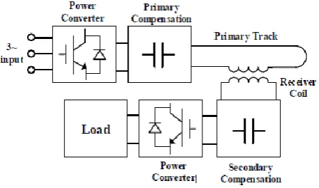
1.1. Inductive Power Transmission
[image:1.595.317.546.528.663.2]Inductive Power Transfer (IPT) systems based on the resonant magnetic induction constitute a new technology which enables power transmission between two systems without physical contacts.
Fig 1. Typical loosely coupled IPT system
© 2019, IRJET | Impact Factor value: 7.211 | ISO 9001:2008 Certified Journal
| Page 6319
in the form of coils to increase the magnetic field of the circuits. In this way, the transmitter coil has a current pass through it that generates a magnetic field. It is coupled to the secondary coil, and when there is a change in transmitter primary current, this induces a voltage in the secondary or receiver coil. The voltage induced in the receiver or secondary coil can then be used to drive a battery charger or other circuitry as required.
2. System Overview
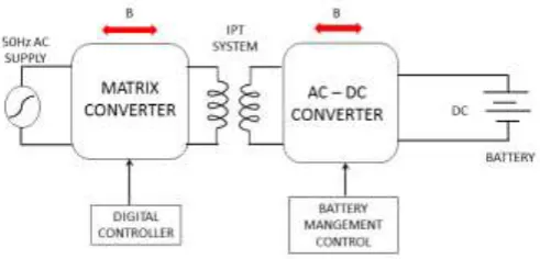
[image:2.595.319.540.261.458.2]The proposed system is used to transmit electric power using matrix converter at the transmitting end and a rectifier at the receiving end. The converter is specifically suitable for establishing grid-to-vehicle and vehicle-to-grid connections through inductive electric vehicle charging and discharging systems. It offers numerous advantages such as safety, convenience, flexibility, isolation and less maintenance.
Fig 2. Proposed IPT system with matrix converter This simplified controller is implemented using basic logic circuit components, without the need for digital signal processor/ field programmable gate array platforms, hereby reducing the complexity and the implementation cost. The converter benefits from resonance frequency tracking capability for the synchronization of switching operations of the converter with the resonant current, that makes it ideal for dynamic IPT systems. Also, it benefits from soft-switching operations to achieve an enhanced efficiency & low electromagnetic interference.
2.1 Basic Circuit Operation Of Matrix Converter At
The Transmitter Side
Power converters play a key role in the performance of IPT systems. Recent developments in IPT systems have heightened the need for high-power, reliable and efficient converters. Normally, these converters take 50 Hz current from mains and convert it to high-frequency using a power electronic converter. These converters have the advantages of the simple and compact topology, bidirectional power flow capability, high quality input-current waveforms, and adjustable input power factor independent of the load.
MCs are used to convert AC mains inputs to an AC output with a different frequency and amplitude directly without any intermediate conversion stage. In order to generate a high-frequency current on the primary side, specific power converters are employed in IPT systems.However, in recent years, there has been an increasing interest in matrix converters . In MCs, the bulky energy storage elements are eliminated and thereby, they have high power density and are more reliable. Specifically, three-phase to single-phase and single-phase to single-phase MCs are of great interest in Inductive Power Transfer systems. A direct soft-switched single-phase ac–ac matrix converter (MC) for bidirectional inductive power transfer (IPT) systems is proposed.
Fig 3. Single-phase ac-ac matrix converter topology used at the transmitter side
Recently, with the decrease in the size and the price of power electronics switches, matrix converter started drawing more research interest. It is most versatile configuration without any limits on the output frequency and amplitude. It replaces the multiple conversion stages and the intermediate energy storage element by a single power conversion stage, and uses a matrix of semiconductor bidirectional switches. This direct frequency converter is characterized by sinusoidal waveforms both at input and output ports, bi-directionality, independent control over input and output frequency. The converter enables attenuation of the harmonic distortions in the grid current. However, the converter is hard-switched, which leads to a lower efficiency and reliability and requires complex commutation techniques.
2.2 Receiver Side converter with battery
management control
[image:2.595.40.286.329.447.2]© 2019, IRJET | Impact Factor value: 7.211 | ISO 9001:2008 Certified Journal
| Page 6320
S1 and S4 switches and closing S2 and S3 switches, thisvoltage is reversed, thus producing a DC output at the load. Using the nomenclature above, the switches S1 and S2 should never be closed at the same time, as this would cause a short circuit on the input voltage source. The same applies
to the switches S3 and S4. The load used here may be a dc
[image:3.595.37.285.197.298.2]load or battery
Fig 4. Single-phase ac-dc converter topology used at the receiver side
3. Battery Management Control At The Receiver
End
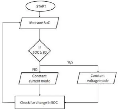
The charging mode selection between the constant current (CC) and the constant voltage (CV) is decided based on the SOC of the battery. If SOC < 80%: Constant Current (CC) mode is selected for charging battery. If SOC >= 80%: Constant Voltage (CV) mode is selected for charging battery. The system consists of two power converters which basically shares a common DC link capacitance. For interfacing the battery with grid, a 1ᵠ full-bridge bidirectional AC to DC converter is used .Bidirectional AC-DC converter acts as a rectifier in the G2V mode of operation and as an inverter in the V2G mode of operation
Fig 5.
Flow chart of CCCV control of AC- DC converter3. Digital Controller For Matrix Converter
A bidirectional IPT system with a direct single-phase ac–ac MC as the primary converter and a rectifier as the secondary converter is used here. This can be achieved by controlling the number energy injection/ regeneration pulses in a specific control cycle. This digital controller is developed using AND, OR, NOT, XOR logic gates, flip-flops, and multiplexers. The controller generates an energy injection/regeneration signal (Sg ) based on the user defined power transfer settings by using selector switches for both positive and negative resonant current half-cycles. Using the proposed power controller, ten power transfer levels can be achieved. Each power level corresponds to a certain number of positive and negative energy injection/regeneration half-cycles and selector states (a1a2a3a4).
The resonant current (ir ), Supply voltage (Vs ), Supply current (ic), and Energy injection/regeneration signal (Sinj/Sreg ) in forward and reverse power transfer modes at power transfer levels are verified conceptually. This shows that using the power controller, the resonant current is directly converted to a digital signal representing 1’s as the positive half cycle and 0’s as the negative half cycle in both directions. Also, the switching diagram of the converter corresponds to the soft switching operation of the converter and it represents the switching signals of the converter (SA1, SA2, SB1, SB2) along with the resonant current, Supply voltage, Supply current, and energy injection/regeneration signal.
3.1 Switching Logic Design
The resonance frequency in an IPT system can slightly deviate from its nominal point due to changes in operating conditions. The deviation of switching operations from the resonance point can dramatically affect the performance of the system. Therefore, constant switching adjustment to the resonance frequency variations is essential to ensure high power transfer efficiency in the system. The resonance frequency tracking capability of the controller enables synchronization of the switching operation of the converters with the resonant current to achieve maximum power transfer with high efficiency.
[image:3.595.51.277.536.742.2]© 2019, IRJET | Impact Factor value: 7.211 | ISO 9001:2008 Certified Journal
| Page 6321
receiver compensation capacitors Ct and Cr . The primary converter is comprised of four bidirectional switches (SA1, SA2, SB1, SB2). A power controller is designed for the ac–ac converter that enables power transfer at the desired level by tuning the energy injection/ regeneration rate in the IPT system. The controller takes resonant current (ir ) and ac supply voltage (Vs ) as feedbacks and generates four switching signals for the matrix converter
In other words, each operation mode starts and ends at current zero-crossing points, forming a half-cycle. The ZCS significantly reduces the complexity of commutation usually required in MCs and eliminates the need commutation techniques. The controller is composed of two main sections: switching logic and frequency divider. The energy injection /regeneration principle and the design methodology are described as follows.
Switching Logic Design
3.2 Modes Of Operation Of The Circuit
Forward Power Transfer
The forward power transfer mode (Sr = 0) enables energy transfer from the transmitter to the receiver dc source. In this case, the MC constantly switches between energy-injection and free-oscillation modes. In energy energy-injection modes, energy is transferred to the IPT system and as a result, the resonant current is increased. In free-oscillation modes, energy transfer to the IPT system is avoided and the resonant current is allowed to circulate in the system and the energy stored in the resonance tank which is used as a source for energy transfer to the IPT system. Since the energy stored in the system reduces, the resonant current decreases. Therefore, switching between these two types of modes enables power transfer regulation in forward power transfer mode. It is clear that the resonant current increases in energy injection modes and it decreases in free-oscillation modes.
Reverse Power Transfer
The reverse power transfer mode, (Sr = 1), is used to enable energy transfer to the transmitter single-phase ac source from the receiver dc source. In this case, the receiver converter acts as an inverter to allow the secondary structure operate as a transmitter and in the primary MC, the
energy-regeneration and free-oscillation modes are engaged. In this case, Req which represents the receiver load reflected to transmitter (shown in Fig. 4) is negative. This means that Req generates power (rather than consuming power) and injects power to the transmitter resonance tank.
In energy-regeneration modes, the MC transfers energy back to the transmitter ac source and therefore the resonant current decreases. This is done by directing the resonant current to the ac source with a reverse polarity and thereby, the energy stored in the resonant tank is injected into the source which results in a reduction in the energy stored in the LC tank and the resonant current. Also, in free oscillation
modes, the primary current is allowed to circulate in the IPT system and thereby, energy regeneration is avoided. However, as a result of the energy transfer from the receiver to transmitter, in free-oscillation modes, the energy stored in the transmitter
resonance tank increases which in turn increases the resonant current. Power transfer regulation in reverse power transfer mode is enabled by continuously switching between these two types of modes.
Forward power transfer mode
Switches SA1 and SB2 conducts
Energy injection process takes place
Signal Sr = 0
Battery charges during this mode
Reverse power transfer mode
Switches SA2 and SB1 conducts
Energy regeneration process takes place
Signal Sr = 1
Battery discharges during this mode
4. Different Power Transfer Levels Obtained Using
The Power Controller
In an IPT system, the power transfer level can be controlled by regulating the energy transfer rate in the system.
Table -1: Power Levels Obtained are tabulated as follows
POWER
LEVELS SELECTOR STATE a1 a2 a3 a4
BATTERY CHARGING CURRENT(A)
BATTERY CHARGING POWER (W)
1 0000 -50.65 -608.9
2 0001 -39.97 -477.5
3 1000 -25.3 -300
4 0010 -23.66 -280.2
5 1100 -20.69 -244.6
© 2019, IRJET | Impact Factor value: 7.211 | ISO 9001:2008 Certified Journal
| Page 6322
7 1001 -15.26 -179.8
8 0101 -11.69 -137.4
9 1101 -9.948 -116.8
10 1010 -7.244 -84.94
11 0110 -5.375 -62.95
12 1111 -2.911 -34.04
4. Simulation Results
Simulation of IPT system with digital power controller and battery management control
Fig.6. IPT System with Digital Power Controller and Battery Management Control
Fig.7. High Frequency Output Voltage and Current of Matrix Converter at Transmitter End
Fig.8. Gate Pulse Generated by Digital Controller for Matrix Converter at Transmitter End
Fig.9. DC Output at the Receiver End of IPT System using Matrix Converter
Fig.10. Output Profile of Battery under CC and CV Mode
5. CONCLUSION
© 2019, IRJET | Impact Factor value: 7.211 | ISO 9001:2008 Certified Journal
| Page 6323
capacitors, the converter is more compact and reliable compared to conventional two-stage converters. The digital controller which is designed based on the energy injection/regeneration principle and is implemented which effectively enables bidirectional power transfer at twelve different power levels. The resonance frequency tracking capability ensures that the converter operates exactly at the resonance frequency of the IPT system and, therefore high efficiency can be achieved. Also, the converter benefits from soft-switching operations that further enhances the efficiency of the converter. Finally, the structure of the single-phase MC along with the simplified controller makes it suitable for inductive charging systems with bidirectional power flow capability. The resonance frequency tracking capability of the converter makes it suitable for dynamic charging systems, in which the system may have variations.
REFERENCES
[1] U. K. Madawala and D. J. Thrimawithana, “A bidirectional
inductive power interface for electric vehicles in v2g systems,” IEEE Trans. Ind. Electron., vol. 58, no. 10, pp. 4789–4796, Oct. 2011.
[2] H. L. Li, A. P. Hu, and G. A. Covic, “A direct ac-ac
converter for inductive power-transfer systems,” IEEE Trans. Power Electron., vol. 27, no. 2, pp. 661–668, Feb. 2012.
[3] U. K. Madawala, M. Neath, and D. J. Thrimawithana, “A
power-frequency controller for bidirectional inductive power transfer systems,” IEEE Trans. Ind. Electron., vol. 60, no. 1, pp. 310–317, Jan. 2013.
[4] M. J. Neath, A. K. Swain, U. K.Madawala, and D. J.
Thrimawithana, “An optimal PID controller for a bidirectional inductive power transfer system using multiobjective genetic algorithm,” IEEE Trans. Power Electron. vol. 29, no. 3, pp. 1523–1531, Mar. 2014.
[5] J. Y. Lee and B. M. Han, “A bidirectional wireless power
transfer EV charger using self-resonant PWM,” IEEE Trans. Power Electron., vol. 30, no. 4, pp. 1784–1787, Apr. 2015.
[6] B. X. Nguyen et al., “An efficiency optimization scheme
for bidirectional inductive power transfer systems,” IEEE Trans. Power Electron., vol. 30, no. 11, pp. 6310– 6319, Nov. 2015.
[7] M. Moghaddami, A. Anzalchi, and A. I. Sarwat,
“Single-stage three-phase ac-ac matrix converter for inductive power transfer systems,” IEEE Trans. Ind. Electron., vol. 63, no. 10, pp. 6613–6622, Oct. 2016.
[8] M. Moghaddami andA. Sarwat, “Self-tuning variable
frequency controller for inductive electric vehicle charging with multiple power levels,” IEEE Trans. Transport. Electrif., vol. 3, no. 2, pp. 488–495, Jun. 2017.
[9] M. Moghaddami and A. Sarwat, “Self-tuned single-phase
ac-ac converter for bidirectional inductive power transfer systems,” in Proc. IEEE Ind. Appl. Soc. Annu. Meeting, Oct. 2017, pp. 1–6.
[10]M. Moghaddami, A. Sundararajan, and A. I. Sarwat, “A