© 2019, IRJET | Impact Factor value: 7.211 | ISO 9001:2008 Certified Journal | Page 8010
A SSR-Based Near Field RFID Reader Antenna
Ajay Dev V
1, Ashess Philip
1, Sharon Shaju
1, Anila P V
21B.Tech, Dept. of Electronics and Communication, M A College of Engineering Kothamangalam,
Kerela, India
2Professor, Dept. of Electronics and Communication, M A College of Engineering Kothamangalam,
Kerela, India
---***---Abstract -
In this paper , a compact near field reader -antenna is proposed for ultra-high frequency (UHF) radio frequency identification (RFID) applications. The antenna structure is composed of two split-ring resonators (SRRs) and miniaturized to a special small size of 21*21*1.6 mm3 for mobile RFID application . The measured bandwidth of antenna prototype is 20 MHz ( 912 - 932 MHz ) with a reflection coefficient less than -10 dB , which covers the China RFID band II ( 920 -925 MHz ) . Simulation shows that the proposed antenna achieves a strong and uniform magnetic field distribution in the near field region.1. INTRODUCTION
Radio-frequency-identification (RFID) has played a major role for automated identifying and tracking objects in various applications, such as warehouse, supply chain, industry , and commerce . Generally, there are two kinds of RFID systems: far-field and near-field system. The far - field RFID systems only operate at UHF ( 840 - 960 MHz) bands using with electromagnetic waves propagating between the readers and tags. Relatively, the near - field RFID systems based on inductive coupling to transfer power and transmit data between the readers and tags. In near-field systems, the inductive coupling stores most of the reactive energy in the magnetic field near to the reader antenna region. Compared to the far-field system, the advantage of near-field system is that the reader antenna will be only affected by high magnetic permeability objects and operates well in close proximity to metals and liquid. The near-field systems can operate at low frequency (LF, 125-134 kHz), high frequency (HF, 13.56 MHz) and UHF bands. The conventional LF/HF near-field RFID tag has complex multiturn loop structure, and the data transmission rate is lower compared to UHF near-field systems. In order to address the size constraint problem, we make a tentative suggestion of a novel type of RFID reader antenna for near- field application. In this paper, we present formally the compact SRR-based RFID antenna and give more details of the near-field characteristics by simulation and measurements.
The compact antenna prototype is fabricated with a special small size of 21 * 21 * 1.6 mm3, which is one of
the smallest dimension of RFID reader antenna in the world. The measured result of prototype shows good impedance matching over 20MHz (912-932 MHz) with reflection coefficient less than -10 dB, which covers the China RFID band II (920-925 MHz). Simulation shows that the antenna features a strong and uniform magnetic field distribution.
2. THEORY OF SRR
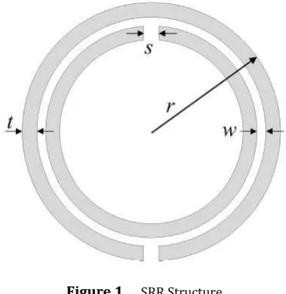
[image:1.595.329.537.462.676.2]Split Ring Resonator (SRR), as shown in Fig. 1, is formed by two different diameter size concentric metal rings with one gap on the opposite position of each one. As a resonator, the inductive effect of SRR is created by the rings while the capacitive effect is determined by the gap between split rings and the gaps at each ring.
Figure 1 . SRR Structure
Volume: 06 Issue: 05 | May 2019 www.irjet.net p-ISSN: 2395-0072
© 2019, IRJET | Impact Factor value: 7.211 | ISO 9001:2008 Certified Journal | Page 8011 and good bandwidth. Due to the high capacitance value
the structure size reduction is possible.
3. ANTENNA DESIGN AND STRUCTURE
[image:2.595.310.563.255.457.2]The configuration of proposed antenna is shown in Fig. 2. The SRR structure and ground are respectively fabricated on the opposite sides of the FR-4 substrate. The SRR structure is formed by two coupled square-rings separated by a gap, each with a split at opposite sides. On the top view of Fig. 2, L1 is the edge side of the fabrication, and L2 is the edge of the outer square. Then, g is the gap between the inner and outer, s1 is the split width of the inner square, and s2 is the outer square. Particularly, the inner square has the same line widthw1, but the outer square has two different line widths of w1 and w2. This can broaden the bandwidth of the antenna. Finally, L4 is the distance between the feed point and a corner of the outer square. On the bottom view, L3 is the long edge of the rectangle ground, and W is the short edge.
[image:2.595.71.256.383.547.2]Figure 2 . Proposed antenna structure
Table 1 . Parameters of proposed antenna
Antenna Square Edge(mm) L1 25 SRR Structure(mm) L2
L4 S1 S2 W1 W2 g
21 4.5 1 1 1 2 0.8 Metal Ground(mm) L3
W 13 4
4 SIMULATION AND MEASUREMENT RESULTS
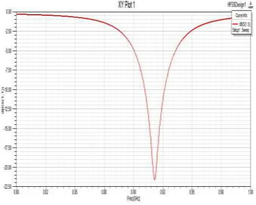
[image:2.595.65.261.601.738.2]The simulated frequency distribution is shown in Fig. 4. Simulations of the proposed antenna were performed using Ansoft High Frequency Structure Simulator (HFSS) software, which uses the finite element method (FEM). The measured impedance bandwidth of the antenna prototype is 20MHz (912-932 MHz) under the condition of reflection coefficient less than ¡10 dB, which agrees well with the simulated results and covers the China RFID Band II standard (920{925 MHz) completely.
Figure 4 . Frequency distribution of proposed antenna
Since the size of SMA connector is comparable to the proposed antenna in Fig. 3 and extends the ground in measurement, the measured result of S11 is better than the simulated result in Fig. 4. The antenna ground is often connected to the PCB in application, so we consider the effect of SMA connector equivalent to the effect of PCB ground. The measurement is more close to practical use rather than simulation.
© 2019, IRJET | Impact Factor value: 7.211 | ISO 9001:2008 Certified Journal | Page 8012
[image:3.595.35.288.235.426.2]Figure 5. Current Distribution Plot
[image:3.595.37.287.461.651.2]Figure 6 a) Magnetic distribution at z=10mm
Figure 6 b) Magnetic distribution at z=20mm
Figs.6(a)&(b) show the magnetic field above the antenna at different xoy planes. The interrogation zone in Figs. 6(a) & (b) is uniform on the most region of antenna, and agrees well with the simulation of current in phase along the antenna in Fig. 5.
5. VARIATION STUDY
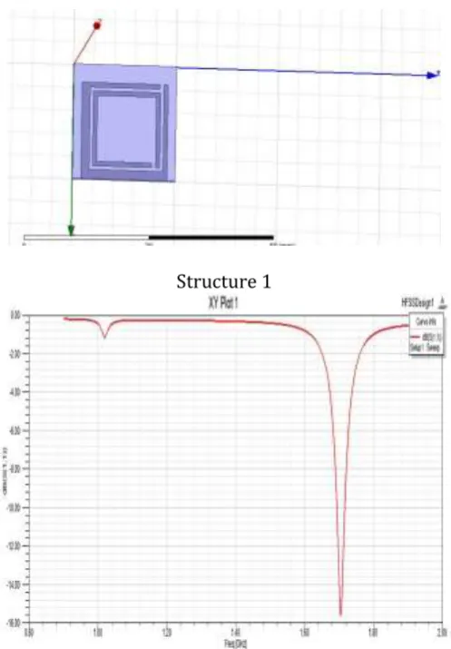
Structure 1
Frequency Distribution Plot of Structure 1
Volume: 06 Issue: 05 | May 2019 www.irjet.net p-ISSN: 2395-0072
© 2019, IRJET | Impact Factor value: 7.211 | ISO 9001:2008 Certified Journal | Page 8013 Frequency Distribution Plot Of Structure 2
Structure 3
Frequency Distribution Plot Of Structure 3
In this modification we are changing the split position of the inner square. An increase in resonant frequency and change of single band to multiband are observations of above modifications. As a result there is a decrease in bandwidth. So the quality factor and selectivity of the antenna increases.
6. CONCLUSIONS
In this paper, the proposed antenna uses two SRRs to obtain a small dimension of 21 * 21 * 1:6mm3. From Table 1 and Fig. 4, the edge of the antenna outer ring is 21 mm, which is approximately equal to 1/16 wavelength at 920 MHz, and the edge of the classical patch antenna must be 163 mm, which is about ½ wavelength at 920 MHz. Thus, the proposed antenna is one of the smallest RFID reader antennas all over the world, which is suitable for mobile application.
Finally, a proposed antenna prototype is fabricated and detects passive UHF RFID tag in near region successfully. It provides the bandwidth of 13MHz (912-932 MHz) with reflection coefficient less than ¡10 dB, which can cover the China RFID band II (920-925 MHz) completely.
REFERENCES
1. Finkenzeller, K., RFID Handbook: Radio-Frequency Identification Fundamentals and Applications, 2nd Edition, Wiley & Sons, New
York, 2004.
2. 2. Nikitin, P. V., K. V. S. Rao, and S. Lazar, \An overview of near field UHF RFID,” Proc. IEEE Int. Conf. on RFID, 167{174, Mar.
2007.
3. Qing, X., C. K. Goh, and Z.-N. Chen, \Segmented loop antenna for UHF near-field RFID applications,” Electron. Lett., Vol. 45,
No. 17, 872{873, Aug. 2009.
4. Qing, X., C. K. Goh, and Z. N. Chen, \A broadband UHF near- field RFID antenna,” IEEE Trans. Antennas Propag., Vol. 58, No. 12, 3829{3838, Dec. 2010.
5. Liu, H.-W., K.-H.Wu, and C.-F. Yang, \UHF reader loop antenna for near-field RFID applications,” Electron. Lett., Vol. 46, No. 1,10{11, Jan. 2010.
BIOGRAPHIES
Prof. Anila P V
Project Guide , Dept. of ECE ,Mar Athanasius College of Engineering ,Kothamangalam, Kerala , India 1’st
© 2019, IRJET | Impact Factor value: 7.211 | ISO 9001:2008 Certified Journal | Page 8014 Ajay Dev V
Student ,B.Tech, ECE, 2015-2019 Mar Athanasius College of Engineering ,Kothamangalam, Kerala , India
Ashess Philip
Student ,B.Tech, ECE, 2015-2019 Mar Athanasius College of Engineering ,Kothamangalam, Kerala , India
Sharon Shaju
Student ,B.Tech, ECE, 2015-2019 Mar Athanasius College of Engineering ,Kothamangalam, Kerala , India
2nd Author
Photo
4th Author
Photo 3rd Author