Manuscript version: Author’s Accepted Manuscript
The version presented in WRAP is the author’s accepted manuscript and may differ from the published version or Version of Record.
Persistent WRAP URL:
http://wrap.warwick.ac.uk/111596
How to cite:
Please refer to published version for the most recent bibliographic citation information. If a published version is known of, the repository item page linked to above, will contain details on accessing it.
Copyright and reuse:
The Warwick Research Archive Portal (WRAP) makes this work by researchers of the University of Warwick available open access under the following conditions.
© 2018, Elsevier. Licensed under the Creative Commons Attribution-NonCommercial-NoDerivatives 4.0 International http://creativecommons.org/licenses/by-nc-nd/4.0/.
Publisher’s statement:
Please refer to the repository item page, publisher’s statement section, for further information.
1
Effects of crosswind and burner aspect ratio on flame characteristics
and flame base drag length of diffusion flames
Fei Tang
1, Qing He
2, Jennifer Wen
11School of Engineering, University of Warwick, Coventry CV4 7AL, UK
2School of Automotive and Transportation Engineering, Hefei University of Technology, Hefei, Anhui 230009, China
Abstract
Experimental investigations were conducted to characterise the impacts of crosswind and burner
aspect ratio on the flame evolution characteristics and flame base drag length of gas diffusion flames
on rectangular burners. The burners have the same surface area of approximately 100 cm2. The tests
to capture the flame base drag length were conducted three times for each condition with the
differences between the original and repeated tests being less than 6%. The thermocouple readings
were corrected for the effect of radiative and convective heat exchange with the surroundings. Overall,
84 independent test conditions were conducted on 4 different burner aspect ratios, 3 fuel supply rates
and 7 crosswind conditions. The changing behaviour of the flame with different burner aspect ratios,
heat release rates and crosswind speeds were carefully analysed. The appearance of “blue flames” in
the upstream edge of the main diffusion flames just above the burner in relatively strong winds was
analysed. Unlike the flame tilt angle and flame height which either increase (the former) or decrease
(the later) monotonically with the increase of wind speed, the flame base drag length was found to
increase with the wind speed firstly until a critical point and then decrease with further increase of the
crosswind for a given heat release rate. This is thought to be due tothe competing influence of thermal
buoyancy and wind induced inertial forces. The transition point for the maximum flame base drag
length with regard to crosswind was found to decrease with the increasing aspect ratio of the burner
for a given heat release rate. A new physics-based correlation considering decay phase with the
crosswinds was proposed for the flame base drag length incorporating all important physical factors
including inertia force, fire induced thermal buoyancy, Froude number, dimensionless heat release rate
and fuel/air density ratio. The proposed formulations were found to correlate well with the current
measurements of gas burner fires as well as some published data in the literature for pool fires on the
ground which were not used in their derivation.
Keywords:
Flame base drag length; Rectangular-source fires; Aspect ratio; Crosswind; Froude number.
Nomenclature
D
the pool size (equivalent diameter or
square length), m
heat release rate, kW
*
D hydraulic diameter, m dimensionless heat release rate
**
D characteristic perimeter diameter, m S the area of burner, m2
Fr Froude number Ta ambient air temperature, K
i
F inertial force , N v* the crosswind speed, m/s
g gravitational acceleration, m/s2 W width of theburner, m
H the pool elevation height from ground., m Greek symbols
L length of theburner, m a air density, kg/m3
drug
L the flame base drag length , m v
the densities of fuel vapor at the
boiling point , kg/m3
3
1.
Introduction
Diffusion flames in crosswinds have attracted considerable interests from fire safety researchers
[1-3]. Most previous studies used circular or square burners while a limited few experiments were
conducted with rectangular burners with different aspect ratios [4-8]. Hasemi and Nishihata [4]
established that the fire source shape (aspect ratio) should be taken into account on the prediction of
flame height and fire plume temperature.Quintiere and Grove [5] investigated the transition behaviour
on flame height and plume temperature from axisymmetric source to line source in a quiescent
condition. Tang et al. [8] experimentally measured mean flame heights and tilt angles on four medium
scale rectangular burners as well as a square pool of 0.205 m × 0.205 m.
In these fire scenarios, the unburnt fuel is close to the burner surface and dragged towards the
downwind direction. The downstream side is preheated by the inclined flame. Both factors can
influence flame spread but their effects may not be the same. The flame drag length is an important
parameter which characterizes such effects and hence of important safety relevance for liquid pool
(tank) fires [3], tunnel fires [9] and flame spread on solid fuels [10, 11]. Dimensionless correlations
for the flame base drag length have been proposed by various investigators [12-21]. Welker and
Sliepcevich [12, 13] correlated the flame base drag length with Froude number and fuel/air density
ratio for relatively low winds. Moorhouse [14] and Johnson [16] studied larger liquefied natural gas
pool fires in crosswinds and correlated the flame base drag length with just the Froude number. Their
correlation was later adopted by Lautkaski [17] for large tank fires through the adjustment via a
laboratory scale (0.1–0.6 m) data with different hydrocarbon fuels in crosswinds and developed a
correlation shown in Eq. (1). Hu et al. [19] studied the effect of sub-atmospheric pressure (64 kPa) on
the flame base drag length. Tang et al. [20] established the relation between flame base drag length
and heat flux through tests on a gas burner of 25 (L) ×5 (W) ×8.5 (H) cm. More recently, Hu et al. [21]
investigated the influence of pool elevation height (the burner is 2-5 cm above ground plane) on flame
base drag length and incorporated the effect of heat release rate as depicted in Eq. (2), wherethe range
of Froude numbers is from 0.25 to 6.25.
(
)
0.5 0.482.375 ( -1)
drag v a
L +D D= Fr
(1)
0.2 0.5 *1/3
0.68 ( ) 2
drag v a
L D= Fr Q − H D
(2)
where Froude number
Fr
=
v gD
2 , dimensionless HRR, *(
5 2)
a p aQ&=Q& c T g D , v is the
crosswind speed, D is the pool size (circulardiameter or square length),
vand
aare the densities ofthe fuel vapour at the boiling point and ambient air, respectively, Ldrag is the flame base drag length
and H is the pool elevation height from ground. For rectangular burners, the pool size D can be replaced
by the equivalent diameter, most previous researchers used the following hydraulic diameter for
equivalent diameter *
D ,
*
(
) (
)
1/ 2(
)
2 2 1
D = LW L W+ = S n+ n
(3)
where the dimensionless HRR can be expressed as:
5
included in the resulting correlations such as Eqs. (1) and (2). However, burner shapes do affect the
burning characteristics of the spreading fire. For example, the burning behaviour of vehicle fires have
been studied for decades mostly by assuming square or circular fire base but in reality they are more
like fires on rectangular sources with different aspect ratios. Such assumption can impact on the
estimated fire hazards and corresponding fire protection measures. In addition, the changing trend of
the flame base drag length in relation to wind condition is not only of practical importance to pool fire
hazards assessment, but it can also shade light on flame spread over solid fuels.
In summary, despite considerable progresses, insight about the effects of crosswind and burner
aspect ratio on the dynamics and flame base drag length of pool fires is still lacking. Associated with this
is the lack of physics based formulations, which incorporate all the important factors including burner
geometry, fuel properties and the complex fluid dynamics to assist fire safety considerations in practical
applications. The present work aims to fill these knowledge gaps by experimentally studying propane
fires on rectangular burners with different aspect ratios in crosswinds of varying speeds, considering
some fine features of the flame behaviour and developing a physics-based correlation to predict the
flame base drag length for pool fires on the ground. The new correlation will also be tested against
some published data in the literature which were not used in their derivation.
2. Experiments
Figure 1a shows the experimental setup consisting of a wind tunnel of 66 m (L) ×1.5 m (W) ×1.3
m (H), a mechanical fan was fixed at one end to provide the longitudinal ventilation, in which the air
m/s. At the test section, the turbulence statistical values of ua rms, ua mean, less than 5%. Here, ua rms, is root-mean-squared fluctuation velocity [m/s], ua mean, is mean of the cross-flow air speed [m/s]. The
following Figure 1b showed that even though the measured longitudinal ventilation velocities
measured by the four probes fluctuated with time slightly, the mean longitudinal wind speed remained
reasonably stable. Four types of burners which consisted of a large sand-filled section over a fine mesh
to mix and release fuel evenly, and a side view charge-coupled device (CCD) to capture flame
evolution. The test section was located just outside the tunnel exit and included four types of gas
burners with the same surface area (S) but different aspect ratios, i.e. the ratio of the long to short rim.
The burner dimensions are 10 cm10 cm, 14.2 cm7.1 cm, 20 cm5 cm and 28.4 cm3.5 cm, giving
aspect ratios “n” of 1, 2, 4 and 8.1, respectively. The burners all have the same height of 30 cm, and
the burner is flush with the ground plane. The pools were made of 2 mm thick steel plate. The setup
was designed to mimic pool fires from fuel spill on the ground.
For the experimental conditions, eleven levels of crosswind speeds, i.e. 0.71 m/s, 0.91 m/s, 1.14
m/s, 1.36 m/s, 1.63 m/s, 1.88 m/s, 2.09 m/s, 2.31 m/s, 2.64 m/s, 3.02 m/s and 3.43 m/s were applied.
Propane gas was supplied at 4.5, 6.5 and 8.5 L/min, giving equivalent heat release rate (HRR) of 7.56,
10.92 and 14.28 kW, respectively. Figure 1c shows the schematic diagram of the thermocouple layout.
The ambient temperature was around 37±2°C during all tests.
The flame base drag length was measured by the scale on the ground from the image frames
recorded by the CCD camera. The measurements were averaged over 750 consecutive frames for each
test. For each condition, 30 seconds of original video recordings were analysed and converted into the
gray scale images (Figure 2b), and then the Otsu method (eg. [8]) was used to identify the flame region
7
obtained and converted to colour contour in Figure 2d for easy reading. As shown in Figure 2d, the
flame base drag length was defined as the length between the burner edges to the location of 50%
flame appearance probability [8], e.g. the flame base drag length is 12.72 cm in Figure 2d. A mass
flow controller (ALICAT) was employed to regulate the fuel flow rate with an accuracy of 0.01
standard liter per minute (SLPM), the range is from 1 to 9 standard liter per minute (SLPM). The
response time is usually several tens of milliseconds. For the thermocouple measurement, K-type
thermocouples (its diameter is 0.5 mm) were used. Its range is from 273 K to 1073 K degrees. Each
test was repeated three times. The thermocouple readings were corrected for the effect of radiative and
convective heat exchange with the surroundings [22-26]. It can be concluded that the impact of such
correction increased with the increasing measurement temperature. When the temperature rise was 828
K, the relative radiation errors was no more than 9%.
Detailed experimental conditions are listed in Table 1. The different combination of the test
conditions were covered in 84 tests. Each test was repeated three times and found to have very good
repeatability with the differences between different tests being less than 6%.
3.
Results and discussion
3.1. The flame characteristics and the evolution of the flame base drag length
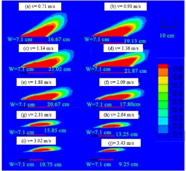
The mean flame evolution on the burner with burner aspect ratio n=2 in crosswinds of six different
speeds is shown in Figure 3. As some gaseous fuel (propane) has been blown towards downstream,
the flame tilt angle increases monotonically with increasing wind speed, and the flame height decreases
monotonically with increasing wind speed. The flame-base drag length has non-monotonic behaviour
and is found to increase with wind speed up to a critical point after which it decreases with wind speed.
For example, when the wind speed increased from 1.36 to 3.43 m/s, the length of the flame base
actually decreased. Although stronger wind blew more fuel downstream, if the wind speed exceeds a
certain value, some unburnt fuel might end up being too far downstream and detached from the flame
edge. The relatively lower temperatures in these downstream regions could not trigger ignition. In such
situations, the actual HRR, overall flame length as well as the length at the flame base decreased as
shown in Figure 3 (e) - (j).
In Figure 4(a), comparison is made for the mean flame characteristics on all the four burners in
crosswinds of 0.71, 2.09 m/s and an intermediate wind speed. The monotonic increase/decrease of the
flame tilt angle and vertical height are also seen here. At the lower wind speed shown on the left, the
burner with the highest aspect ratio, i.e. the width (W) along the wind direction and longest length
facing the wind, is most strongly affected by the wind, resulting in the largest flame base drag length.
But for the higher wind speed, on the contrary, the flames on all burners are smaller with the two
burners shown in Figure (c3) and (c4) with the higher aspect ratios being most obvious. This supports
our analysis that once wind speed exceeds a critical value, some unburnt fuel is blown away further
downstream and unable to ignite. Even stronger wind might extinguish the flame in certain conditions.
In Figure 4(b), snapshots of the instantaneous characteristics on all the four burners in crosswinds
of 0.71, 2.09 m/s and an intermediate wind speed are plotted. Some pockets of blue flames are seen on
all burners at the upstream edge of the main diffusion flames for relatively strong wind. As shown in
Figures 4b (b1 to b4), they started to appear on the four burners at wind speed of 1.63, 1.36, 1.14 and
9
2.09 m/s. Generally, fuel air mixing in diffusion flames are due to air entrainment. In the cases of
strong winds, the fuel is heavily blown towards downstream by fresh air and the main diffusion flames
are mostly burning beyond the burner edge. The observed broad blue flames are thought to be highly
strained diffusion flames where the residence time was insufficient for soot formation.
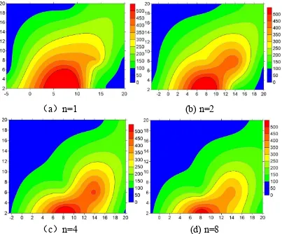
In Figure 5, the vertical temperature rise at different heights are plotted against the horizontal
locations of the thermocouples for the burner with n=2 and HRR=10.92 kW. Figures 6 and 7 present
the temperature field evolution (the thermocouple layout can be seen in Figure 1c). Here the shaded
temperature contours 2 cm above the ground were generated by the Surfer software (www.
Goldensoftware.com) from the discrete thermocouple readings on all four burners with HRR=7.56 kW
and v=0.71 m/s, 2.09 m/s, respectively. By comparing the temperature field for the two different cross
winds of 0.71 m/s, 2.09 m/s. Overall, it is clear from Figs. 3, 4, 6 and 7 that with increasing wind speed
the volumetric heat release increases significantly: the observed flame volumes and the volumetric
residence time both decrease due to the higher wind speeds. There is clearly a transition to a more
momentum dominated mixing process. Since these flames are moving into the lower portions of the
boundary layer with increased velocity, this is the region where mixing rates are most intense. The
error bar is also shown in Figure 5.
Figure 8 presents the measured flame base drag lengths for each burner in different crosswinds
differences between the original and repeated tests to be less than 6%. As discussed earlier, the wind
facing cross-sectional area increases with increasing burner aspect ratio, rendering the flammable
mixture to be brought to the downstream region more easily. The flame base drag length initially
increases with the increase in the crosswind speed due to enhanced fuel air mixing, but after the later
reaches a critical value, it starts to decrease with further increase in the crosswind speed. There exists
a critical wind speed at which the flame base drag length peaked. The results here also indicates that
this critical wind speed decrease with the increase of the burner aspect ratio. In addition, the critical
wind speed for each burner is found to correspond to the wind speed for the appearance of localised
premixed blue flame at the upwind edge above the burner, i.e. 1.63, 1.36, 1.14 and 0.91 m/s for the
conditions tested.
3.2. Comparison with previous correlations and measurements
Figure 9 compares the present measurements with some previous correlations of dimensionless
flame base drag lengths. The correlations of Mudan [14], Moorhouse [15], Johnson [16], Lautkaski
[17] are found to significantly under-predict the measurements for most burner aspect ratios as their
correlations were derived with measurements on burners elevated above the ground but the elevation
height was not included in the correlation, especially the non-monotonic evolution of the flame-base
drag lengths with crosswind velocity in this experimental study cannot be predicted by previous
11
[image:12.595.183.542.74.227.2]Hu et al. [21] subsequently incorporated burner elevation in their correlation, but as shown in
Figure 9b, their new correlation still significantly under-predicts the data even if the elevation height
“H” in Eq. (2) was set to zero. Their tests conducted with the burner elevated between 2 to 5 cm also
showed that the flame base drag length in the 2 cm tests were almost twice that in the 3 cm tests.
Further increase in the burner elevation heights were found to have less influence, implying that the
flame base drag length change rapidly for small burner elevation heights (<3 cm). In Figure 9c, the
measurements of Welker and Sliepcevich [12] with the burner directly sitting on the ground are in very
good agreement with the present data, when the crosswinds are between 0.4 and 2.05 m/s. It is found
that the dimensionless flame base drag length is higher than the results of Hu et al. [19] with 3cm
burner elevation. ForFr2.5, the data of Hu et al. did not show any declining of the flame base
drag length as the present data and that of Welker and Sliepcevich [12], where it’s Fr of all tests are
lower than 2.5; but just slower rate of increase. The range of Froude numbers and Reynolds number for
the previous works can be found in Table 2.
In summary, although qualitatively the non-monotonic evolution of the flame-base drag lengths
with the change of the crosswind speed cannot be captured by the previous correlations, which did not
incorporate the effect of pool aspect ratio and relative strong wind on the flame-base drag length. As
and the current experimental measurements.
3.2 New correlation for flame base drag length of pool fires on the ground
The above analysis and comparison indicated the need for a new correlation which can
incorporate all the important factors not fully considered in previous correlations. As shown in Figure
2, the major influencing factors of the flame base drag length include the following:
1. The speed of the crosswind represented by the inertial force
F
i [18].2. The heat release rate (HRR)
3. The dimensions of the rectangular burner.
This not only influences the wind facing surface area of the flame but also distances the flame
needs to be blown downstream to beyond the burner edge (see Figures 1 and 2). The long rim of burner
is windward (see Figure 1), the larger burner aspect ratio, the more the extent of downwind stretch
easily for a given wind speed.
4. The fuel (or fuel vapour for liquid pool fire)/air density ratio
The larger the fuel/air density ratio, the smaller the buoyancy forces and the harder for the fire
plume to rise.
From the above analysis, the flame base draglength is dependent on both buoyancy Fb (embed in
both HRR and the fuel/air density ratio) and inertial forces Fi. Figure 10 plots the former as a function
of Fr. It can be that whenFr 2.5, the flame base drag length increases with the increase of Fr and it
decreases with further increase of Fr when Fr2.5. The following correlation is proposed for pool
fire on the ground:
13
where the coefficients and constants k, m, j and h are determined from best fitting to the present data.
Fr number is Fr v gW
= 2 , the length scale is W in the calculations of the Fr number in Figs. 10-12.
Figure 11 plots the relationship of dimensionless flame base drag length with other factors based
on Eq. (9) and shows relatively large discrepancies. Although Tang et al. [20] used the hydraulic
diameter defined in their correlation and achieved good agreement with their data, their tests only used
one burner of 25 cm (L) ×5 cm (W) ×8.5 cm (H).
The above analysis indicated that the hydraulic diameter defined by Eq. (3) does not fully capture
the influence of the pool shape, if Lf f W (or n
~
), such as a line burner, the hydraulic diameter*
D based on Eq. (3) will approach zero. This is unphysical. A characteristics equivalent diameter
based on the pool perimeter was proposed by Tang et al. [8] and shown in Eq. (10). This definition
was based on the burning rate and flame tilt characteristics of radiation-controlled rectangular
hydrocarbon pool fires under different cross winds (the burner dimensions of n=1 are 20.5 cm20.5
cm). The underlying assumption of this formulation is that the air entrainment from the sides has
dominating effect on the rate of combustion and flame height.
** 2 1/ 2 1
2L W S ( )
D n
n
+
= = +
(10)
Using the equivalent diameter defined in Eq. (10), equivalent dimensionless HRR expressed in
Eq. (4) and applying least square fitting to the present data only, the coefficients/constants in Eq. (9)
are determined as shown in Eq. (11), where the crosswinds is over 0.4 m/s. In Figure 12, the new
correlation is plotted with the present data as well as the published data (the cross winds are from 0.4
m/s to 2.05 m/s) of Welker and Sliepcevich [12], Wecker [13] for liquid pool fires of n-hexane,
17-200 kW, and the 20 m diameter liquified natural gas pool fire of Mizner [27], whose test was
conducted in cross wind of 6.5 m/s. When the original crosswinds were from 0.20 m/s to 2.05 m/s and
the burner diameters were between 10.16 cm and 60.96 cm, the Fr of Welker’s measurement were
between 0.25 and 1.22, and the Reynolds number of Welker and Sliepcevich from 2E+03 to 3.76E+07.
It can be seen that these independent tests which were mostly captured by the present correlation with
the maximum discrepancy being less than 16% except the case with very low wind speed of 0.4 m/s.
Because the fire was mostly buoyancy controlled, the effect of the limited inertial forces induced by
the very low crosswind only had minor influences. Meanwhile, as shown in Figure 12, it is also can
be found that this new correlation cannot predict the conditions under different side wall height [21].
(11)
If the length scale (W) in the calculations of the Fr number in Figs. 10-12 was changed into D*
and D**. The flame base drag length calculated based on D* and D** respectively can be found in
Figs. 13 and 14, where the Fr was denoted as Fr* and Fr**. It shows relatively large discrepancies.
4.
Conclusions
A series of experiments have been carried out to investigate the effects of crosswind and burner
aspect ratio on flame characteristics and flame base drag length of pool fires on rectangular burners
15
downstream, the actual flame base extended beyond the burner edge. The flame base drag length was
found to increase firstly and then decreases with the increasing crosswind speed. There is a critical
crosswind speed at which the flame base drag length peaked. The critical crosswind speed was found
to decrease with the increasing burner aspect ratio and HRR.
Below the critical wind speed, the burner with the highest aspect ratio, i.e. the width (W) along
the wind direction and longest length facing the wind, was most strongly affected by the wind, resulting in
the largest flame base length. Above the critical wind speed, on the contrary, the flames on all burners were
smaller as some unburnt fuel is blown away further downstream and unable to ignite. Pockets of broad
blue flames have been observed above the burner and in the upstream edge of the main diffusion flames in
relatively large wind condition. These are thought to be highly strained diffusion flames where the
residence time was insufficient for soot formation.
Further quantified analysis also revealed that the flame base drag length increases with the
increase of FrwhenFr2.5; and decreases with the increase of Fr after it peaks at Fr=2.5 for all
the burners tested. A new correlation, which incorporates all the major influencing factors including
the burner aspect ratios, Froude number, dimensionless heat release rates, and fuel (or fuel vapour)/air
density ratio, has been proposed. The new formula was found to correlate well the present as well as
some published test data of different liquid fuels which were not used in their derivation for pool fires
fires on land.
Acknowledgements
The authors acknowledge the European Commission’s Marie Curie International Fellowship
scheme (Grant number 655138) which supported Dr Fei Tang’s stay at University of Warwick, and
National Nature Science Funds of China under Grant No. 51776060.
References
[1] Y. Oka, H. Kurioka, H. Satoh, et al. Fire Saf. Sci. Proc. Sixth Int. Symp., 6 (2000) 1101-1112.
[2] R.O. Carvel, A.N. Beard, P.W.A. Jowitt, Civ. Eng. Syst., 18 (4) (2001) 279-302.
[3] C. S. Lam, E. J. Weckman, Fire Saf. J. 78(2015) 130-141.
[4] Y. Hasemi, M. Nishihata. Fire Safety Sci. 2 (1988)275–284
[5] J.G. Quintiere, B.S. Grove. Proc. Combust. Inst. 27 (1998) 757–766.
[6] J.A.R. Woods, B.A. Fleck, L.W. Kostiuk, Combust. Flame, 146 (2006) 379-390.
[7] R. Tu, J. Fang, Y.M. Zhang, J. Zhang, Y. Zeng, Proc. Combust. Inst. 34(2013)2591-2598.
[8] F. Tang, L.H. Hu, X.C. Zhang, X.L. Zhang, M.S. Dong. Fuel 139 (2015) 18-25.
[9] A. Lönnermark, I. Haukur, Fire Technol. 42 (4) (2006) 283–302.
[10]A.C. Fernandez-Pello, Combust. Flame 36 (1979) 63–78.
[11]V.B. Apte, R.W. Bilger , A.R. Green , J.G. Quintiere , Combust. Flame 85 (1991) 169–184.
17
[13]J.R. Welker, The Effect of Wind on Uncontrolled Buoyant Diffusion Flames from Burning Liquids.
Ph.D. thesis, The University of Oklahoma Graduate College, Norman, OK, 1965.
[14]K. Mudan. Prog. Energy Combust Sci. 10 (1984) 59-80.
[15]J. Moorhouse, I. Chem. E. Symp. Ser. 71 (1982) 507–524.
[16]A.D. Johnson, I. Chem. E. Symp. Ser. 130 (1992) 507–524.
[17]R. Lautkaski. J. Loss Prevent. Process. Ind. 5 (1992) 175–180.
[18]P.K. Raj. Fire Technol. 46 (3) (2010) 579-609
[19]L.H. Hu, X.L. Zhang, M.A. Delichatsiso, L. Wu, C. Kuang. Proc. Combust. Inst. 36 (2017)
3105-3112
[20]W. Tang, C.H. Miller, M. J. Gollner. Proc. Combust. Inst. 36 (2017) 3253-3261.
[21]L.H. Hu, X.Z. Zhang, X.L. Zhang, C. Kuang. Fuel 182 (2017) 857-863.
[22]G. Cox, R. Chitty. Combust. Flame 60 (3) (1985) 219–232.
[23]J. Dupuy, J. Marechal, D. Morvan. Combust. Flame 135 (1) (2003)65–76.
[24]H.X. Wan, Z.H. Gao, J. Ji, J.H. Sun, Y.M. Zhang, K.Y. Li. Combust. Flame 190(2018)260-269.
[25]S. Brohez, C. Delvosalle. Fire Saf. J. 39 (2004) 399–411.
[26]M. Tagawa, Y. Ohta. Combust. Flame 109 (1997) 549-560.
[27]G.A. Mizner, J.A. Eyre. Large scale LNG and LPG pool fires. Institution of chemical engineers
Figure captions
Figure 1. Sketch of the experimental rig.
Figure 2. Definition of the flame base drag and illustration of the underlying physics.
(n=2, HRR=7.56 kW, v=0.71 m/s)
Figure 3. Flame evolution on the burner with n=2 and HRR=10.92 kW in different crosswinds..
Figure 4. Flame evolution on all four burners in crosswinds.
Figure 5. Vertical temperature rise at different vertical heights [the burner with n=2 and HRR=10.92
kW]
Figure 6. Temperature field evolution on all four burners with v=0.71m/s and HRR=7.56 kW.
(The x-coordinate and the y-coordinate are the spatial positions, as shown in Figure 1b)
Figure 7. Temperature field evolution on all four burners with v=2.09 m/s and HRR=7.56 kW.
Figure 8. The measured flame base drag lengths for all the test conditions.
Figure 9. Comparison with previous correlations and measurements.
Figure 10. Relationship between flame base drag length for all burners andFr.
Figure 11. Dimensionless flame base drag length based on the hydraulic diameter D*.
Figure 12. Correlation of the dimensionless flame base drag length based on the equivalent diameter
D** of Tang et al. [8].
Figure 13. Dimensionless flame base drag length based on D* and new *
Fr number (length scale W
was changed to D*, it gives
2 * * v Fr gD = )
Figure 14. Dimensionless flame base drag length based on D** and new **
Fr number (length scale
W was changed to D**, it gives
(a) Schematic diagram of experimental rig.
0 50 100 150 200 250 300
0.6 0.8 1.0 1.2 1.4
Probe 1 Probe 2 Probe 3 Probe 4
,
,
=5%
a rms
a mean
u
u
Velocity
(m/s)
Time (s)
0.91 m/s
Anemometer
(b) Crosswind speed vs with time
[image:21.595.105.521.76.256.2]21
(a) original flame image. (b) gray scale images
[image:22.595.98.521.145.468.2](c) average flame probability distribution (d) colour contour of flame probability.
Figure 2. Definition of the flame base drag length and illustration of the underlying physics.
23
(a) The mean flame characteristics.
[image:24.595.103.514.71.708.2](b) The instantaneous flame characteristics.
-4 -2 0 2 4 6 8 10 12 14 16 18 20 22 0 100 200 300 400 500 600 700 800 900
Vertical heights Z v=0.71 m/s
△
T
(
K
)
Z= 2 cm Z= 6 cm Z= 8 cm Z= 20 cm
Horizontal distance from the burner centreline (cm) (a)
-4 -2 0 2 4 6 8 10 12 14 16 18 20 22
0 100 200 300 400 500 600 700 800 900
Horizontal distance from the burner centreline (cm) Vertical heights Z
Z= 2 cm Z= 6 cm Z= 8 cm Z= 20 cm
[image:25.595.123.497.165.304.2](b) △ T ( K ) v=2.09 m/s
25
(
a
)
n=1 (b) n=2
[image:26.595.111.514.250.584.2](
c
)
n=4 (d) n=8
Figure 6. Temperature field evolution on all four burners with v=0.71m/s and HRR=7.56 kW.
(
a
)
n=1 (b) n=2
[image:27.595.113.513.252.599.2](
c
)
n=4 (d) n=8
27
0.6 0.9 1.2 1.5 1.8 2.1 2.4 2.7 3.0 3.3 3.6 5 10 15 20 25 30 HRR Crosswind(m/s)
(a) n=1
7.56 kW 10.92 kW 14.28 kW Ldr ag ( cm )0.6 0.9 1.2 1.5 1.8 2.1 2.4 2.7 3.0 3.3 3.6 5 10 15 20 25 30 HRR Crosswind(m/s)
(b) n = 2
7.56 kW 10.92 kW 14.28 kW Ldr ag ( cm )
0.6 0.9 1.2 1.5 1.8 2.1 2.4 2.7 3.0 3.3 3.6 5 10 15 20 25 30 Crosswind (m/s) 7.56 kW 10.92 kW 14.28 kW (c) n=4 Ldr ag ( cm ) HRR
[image:28.595.123.505.244.541.2]0.6 0.9 1.2 1.5 1.8 2.1 2.4 2.7 3.0 3.3 3.6 0 5 10 15 20 25 30 Crosswind(m/s) 7.56 kW 10.92 kW 14.28 kW (c) n=8 Ldr ag ( cm ) HRR
0 2 4 6 8 10 12 14 16 18 0 1 2 3 4 5 6 7 8 9 10
Mudan [14] Moorhouse [15]
Lautkaski [17] Johnson [16] drag L W W +
n=4; HRR=7.56 kW n=4; HRR=10.92 kW n=4; HRR=14.28 kW n=8.1; HRR=7.56 kW n=8.1; HRR=10.92 kW n=8.1; HRR=14.28 kW n=1; HRR= 7.56 kW
n=1; HRR=10.92 kW n=1; HRR=14.28 kW n=2; HRR=7.56 kW
n=2; HRR=10.92 kW n=2; HRR=14.28 kW
(a)
Fr
1.0 1.2 1.4 1.6 1.8 2.0 2.2 2.4 2.6 2.8 3.0
0 1 2 3 4 5 6 7 8 9 10
0.2 0.5 *1/3
0.68 ( ) 2
drag v a
L W= Fr Q −HW n=8.1; HRR=7.56 kW
n=8.1; HRR=10.92 kW n=8.1; HRR=14.28 kW
(
b
)
n=4; HRR=7.56 kW n=4; HRR=10.92 kW n=4; HRR=14.28 kW n=1; HRR= 7.56 kW
n=1; HRR=10.92 kW n=1; HRR=14.28 kW n=2; HRR=7.56 kW
n=2; HRR=10.92 kW n=2; HRR=14.28 kW
Hu et al. [21]
0.2 *1/3
Fr Q
drag
L W
0.6 0.8 1.0 1.2 1.4 1.6 1.8 2.0 2.2 2.4 2.6 0 1 2 3 4 5 6 7 8
This study, HRR= 7.56 kW This study, HRR= 10.92 kW This study, HRR= 41.28 kW
Hu et al. [19]
Welker and Sliepcevich [12]
n=1
drag L W W + 0.2 0.5( v)
a
Fr
(c)
[image:29.595.166.432.110.724.2]29
0.5 1.0 1.5 2.0 2.5 3.0 3.5 4.0 4.5 5.0 5.5 6.0 6.5 0.0
0.5 1.0 1.5 2.0 2.5 3.0 3.5 4.0 4.5 5.0 5.5 6.0 6.5 7.0
(
)
0.5 0.5v a
Fr
n=8.1; HRR= 7.56 kW n=8.1; HRR= 10.92 kW n=8.1; HRR= 14.28 kW n=4; HRR= 7.56 kW
n=4; HRR= 10.92 kW n=4; HRR= 14.28 kW
n=2; HRR= 7.56 kW n=2; HRR= 10.92 kW n=2; HRR= 14.28 kW
n=1; HRR= 7.56 kW
n=1; HRR= 10.92 kW
[image:31.595.161.439.165.403.2]n=1; HRR= 14.28 kW
31
0.0 0.5 1.0 1.5 2.0 2.5 3.0 3.5 4.0 4.5 5.0
0 1 2 3 4 5 6
With different side wall height effect Mizner [27] Hu [21]
R2=0.84
(
)
0.50.5
v a
Fr
Slope = 0.80 Slope = - 0.39
R2=0.86 Welker andSliepcevich [12],Welker [13]
n=8; HRR= 7.56 kW n=8; HRR= 10.92 kW n=8; HRR= 14.28 kW n=2; HRR= 7.56 kW n=2; HRR= 10.92 kW n=2; HRR= 14.28 kW n=4; HRR= 7.56 kW
n=4; HRR= 10.92 kW n=4; HRR= 14.28 kW
n=1; HRR= 7.56 kW
n=1; HRR= 10.92 kW
n=1; HRR= 14.28 kW
[image:32.595.148.445.164.394.2]The crosswinds are below 0.4 m/s
Figure 12. Correlation of the dimensionless flame base drag length based on the
0.5 1.0 1.5 2.0 2.5 3.0 3.5 4.0 4.5 5.0 0.0 0.5 1.0 1.5 2.0 2.5 3.0 3.5 4.0 4.5 5.0
n=8.1; HRR= 7.56 kW n=8.1; HRR= 10.92 kW n=8.1; HRR= 14.28 kW n=4; HRR= 7.56 kW
n=4; HRR= 10.92 kW n=4; HRR= 14.28 kW
n=2; HRR= 7.56 kW n=2; HRR= 10.92 kW n=2; HRR= 14.28 kW
n=1; HRR= 7.56 kW
n=1; HRR= 10.92 kW
n=1; HRR= 14.28 kW
(
)
0.5 *0.5v a
[image:33.595.169.446.161.377.2]Fr
Figure 13. Dimensionless flame base drag length based on D* and new *
Fr number (length
scale W was changed to D*, it gives
33
0 2 4 6 8
0.0 0.5 1.0 1.5 2.0 2.5 3.0 3.5 4.0 4.5 5.0
n=8.1; HRR= 7.56 kW n=8.1; HRR= 10.92 kW n=8.1; HRR= 14.28 kW n=4; HRR= 7.56 kW
n=4; HRR= 10.92 kW n=4; HRR= 14.28 kW
n=2; HRR= 7.56 kW n=2; HRR= 10.92 kW n=2; HRR= 14.28 kW
n=1; HRR= 7.56 kW
n=1; HRR= 10.92 kW
n=1; HRR= 14.28 kW
(
)
0.5 **0.5v a
[image:34.595.178.456.164.375.2]Fr
Figure 14. Dimensionless flame base drag length based on D** and new **
Fr number
(length scale W was changed to D**, it gives
Table 1. The experimental conditions
Burner shape
HRR(kW)
Cross wind
(m/s) n= L/W L (cm) W (cm)
1 10 10 7.56-14.28 0.71-3.43
2 14.2 7.1 7.56-14.28 0.71-3.43
4 20 5 7.56-14.28 0.71-3.43
35
Table 2. Comparison of the range of Froude numbers and Reynolds numbers with previous works
Fr number Re number
Welker and Sliepcevich [12] 0.03 to 0.98 2E+03 to 8.24E+04
Mudan [14] 0.02 to 3.0 2.03E+03 to 1.50E+07
Moorhouse [15] 0.02 to 3.0 8.39E+05 to1.50E+07
Johnson [16] 0.02 to 0.4 2.92E+05 to 2.39E+07
Lattkaski [17] 0.08 to 0.1 8.31E+06 to 7.03E+07
Raj [18] 0.03 to 0.98 2E+03 to3.76E+07
Hu [21] 0.25 to 6.25 5.41E+03 to 3.38E+04


![Figure 5. Vertical temperature rise at different vertical heights [the burner with n=2 and HRR=10.92 kW]](https://thumb-us.123doks.com/thumbv2/123dok_us/9426135.446819/25.595.123.497.165.304/figure-vertical-temperature-rise-different-vertical-heights-burner.webp)