Space Flight Operations Contract
Contract NAS9-20000 DRD - 1.4.3.8-a
HAL/S LANGUAGE SPECIFICATION
PASS 32.0/BFS 17.0
HAL/S LANGUAGE SPECIFICATION
Approved by
Original Approval Obtained
Barbara Whitfield, Manager HAL/S Compiler and Application Tools
Original Approval Obtained
Monica Leone, Director Application Tools Build and Data Reconfiguration
32.0/17.0
The HAL/S Language Specification has been revised and issued on the following dates(s):1
Issue Revision Date Change Authority
Sections Changed
29.0/14.0 03/05/99 CR13043 - pp. Ix, x, xi, xii, iii - p. 1-2
- pp. 2-1, 2-3, 2-4, 2-6, 2-7, 2-8 - pp. 3-1, 3-2, 3-3, 3-6, 3-8, 3-9, 3-10,
3-11, 3-12, 3-13
- pp. 4-1, 4-3, 4-4, 4-5, 4-7, 4-8, 4-9, 10, 11, 13, 14, 15, 4-16, 4-17, 4-18, 4-19, 4-20
- pp. 5-1, 5-2, 5-3, 5-4, 5-6, 5-7, 5-8, 5-9, 5-10, 5-11, 5-12, 5-14
- pp. 1, 2, 4, 6, 8, 12, 6-13, 6-14, 6-15, 6-16, 6-18, 6-19, 20, 21, 22, 24, 25, 6-26, 6-27, 6-28
- pp. 7-1, 7-2, 7-3, 7-4, 7-5, 7-6, 7-7, 7-8, 7-9, 7-11, 7-12, 7-13, 7-14, 7-15
- pp. 8-3, 8-5, 8-8, 8-9, 8-10 - pp. 9-1, 9-2, 9-4
- pp. 3, 4, 7, 8, 9, 10-11, 10-13, 10-14, 10-15, 10-16, 10-18
- pp. 11-2, 11-4, 11-6, 11-10, 11-12, 13, 14, 16, 17, 11-18, 11-19, 11-20, 11-21, 11-23, 24, 25, 26, 27, 11-28, 11-29, 11-30
- pp. A-3, A-4, A-5, A-6, A-7, A-8, A-9 - pp. C-1, C-2, C-4, C-5
- p. D-1 - p. E-1 - p. F-1 - p. H-2, H-3
1. A table containing the Revision History of this document prior to the USA contract can be found in Appendix J.
Revision Log Cont’d
Issue Revision Date Change Authority
Sections Changed
CR12935A 4.5 - p. 4-13 CR13813 7.4 -p. 7-6 CR13956 4.8 -p. 4-19 CR14062 3.7.2
3.7.3 Appx D Index
-p. 3-9 -p. 3-9 -p. D-1
-pp. INDEX-1 to INDEX-10 CR14215B 6.5.2
Appx D
-p. 6-23 -p. D-1
CR14216A Preface
DR109063 App. C - p. C-4 DR109083 6.1.1 - p. 6-3 30.0/15.0 03/27/00 CR12711 11.4.1 - p. 11-12
CR13212 4.5 11.4.3
- p. 4-12 - p. 11-15 CR13217 11.4.2
App. A App. G Index
- p. 11-15 - pp. A-1 to A-6 - pp. G-1 to G-9
- pp. INDEX-1 to INDEX-4 CR13236 4.5
7.4
- p. 4-13 - p. 7-6 31.0/16.0 09/07/01 CR13454
7.4 Appx H
cover pages, preface -p. 7-6
Revision Log Cont’d
Issue Revision Date Change Authority
Sections Changed
32.0/17.0 11/05 CR13538 7.4
11.4.1 11.4.10
-p. 7-6 -p. 11-11 -p. 11-23 CR13652 7.4
11.4.8 11.4.9
-p. 7-6 -p. 11-19 -p. 11-21 CR13704A 6.4
7.4
-p. 6-18 -p. 7-6 CR13754A 6.4
7.4
-p. 6-19 -p. 7-6 CR13813 7.4 -p. 7-6 CR13956 4.8 -p. 4-19 CR14062 3.7.2
3.7.3 Appx D Index
-p. 3-9 -p. 3-9 -p. D-1
-pp. INDEX-1 to INDEX-10 CR14215B 6.5.2
Appx D
-p. 6-23 -p. D-1
32.0/17.0
The current status of all pages in this document is as shown below:
Page No. Change No.
All 32.0/17.0
Preface
The HAL/S Language Specification was developed by Intermetrics, Inc., and is currently maintained by the HAL/S project of United Space Alliance.
The HAL/S programming language accomplishes three significant objectives:
• increased readability, through the use of a natural two-dimensional mathematical format;
• increased reliability, by providing for selective recognition of common data and subroutines, and by incorporating specific data-protect features;
• real-time control facility, by including a comprehensive set of real-time control commands and signal conditions.
Although HAL/S is designed primarily for programming on-board computers, it is general enough to meet nearly all the needs in the production, verification, and support of aero-space and other real-time applications.
The design of HAL/S exhibits a number of influences, the greatest being the syntax of PL/1 and ALGOL, and the two-dimensional format of MAC/360, a language developed at the Charles Stark Draper Laboratory. With respect to the latter, fundamental contribu-tions to the concept and implementation of MAC were made by Dr. J. Halcombe Laning of the Draper Laboratory.
The primary responsibility is with USA, Department, 01635A7.
Table of Contents
i November 2005
v November 2005 Figure 2-1 WAIT statement (typical syntax diagram)... 2-1 Figure 2-2 HAL/S character set ... 2-3 Figure 2-3 Subscript Diagram ... 2-7 Figure 3-1 unit of compilation - #1 ... 3-1 Figure 3-2 PROGRAM block - #2 ... 3-2 Figure 3-3 PROCEDURE, FUNCTION, TASK block - #3 ... 3-3 Figure 3-4 UPDATE block - #4 ... 3-4 Figure 3-5 COMPOOL block - #5... 3-5 Figure 3-6 PROGRAM, PROCEDURE, FUNCTION, COMPOOL template - #6 ... 3-6 Figure 3-7 COMPOOL, PROGRAM, TASK, UPDATE header statement - #7 ... 3-7 Figure 3-8 PROCEDURE header statement - #8 ... 3-8 Figure 3-9 FUNCTION header statement - #9... 3-9 Figure 3-10 closing of block - #10... 3-11 Figure 3-11 Name Scope Examples ... 3-12 Figure 4-1 HAL/S DATA TYPES AND ORGANIZATIONS ... 4-1 Figure 4-2 declare group - #11 ... 4-2 Figure 4-3 replace statement - #12... 4-2 Figure 4-4 parametric replace reference - #12.1 ... 4-3 Figure 4-5 Creating Identifiers With Replace Macros ... 4-5 Figure 4-6 Tree diagram for a typical structure template ... 4-6 Figure 4-7 structure template statement - #13... 4-7 Figure 4-8 structure template examples ... 4-9 Figure 4-9 declaration statement - #14 ... 4-10 Figure 4-10 data declarative attributes - #15 ... 4-11 Figure 4-11 Rigid Structure Example... 4-14 Figure 4-12 Label declarative attributes - #16 ... 4-14 Figure 4-13 type specification - #17... 4-15 Figure 4-14 initialization specification - #18 ... 4-18 Figure 5-1 Referencing Structures... 5-2 Figure 5-2 Subscripting - #19... 5-2 Figure 5-3 variable - #20... 5-3 Figure 5-4 subscript construct - #21 ... 5-4 Figure 5-5 Subscript examples ... 5-5 Figure 5-6 componoent, array, and structure subscripts - #22 ... 5-6 Figure 5-7 Structure Subscripting Examples ... 5-8 Figure 5-8 Structure and Array Subscripting Examples... 5-9 Figure 5-9 Matrix and Array Subscripting Examples... 5-10 Figure 5-10 Property of Arayness Exapmle ... 5-11 Figure 5-11 Structure Unraveling Example... 5-13 Figure 6-1 expression - #23 ... 6-1 Figure 6-2 arithmetic expression - #24 ... 6-2 Figure 6-3 arithmetic operand - #25... 6-5 Figure 6-4 bit expression - #26 ... 6-6 Figure 6-5 bit operand - #27 ... 6-7
List of Tables
ix November 2005
1.0 INTRODUCTION
HAL/S is a programming language developed by Intermetrics, Inc., for the flight software of NASA programs. HAL/S is intended to satisfy virtually all of the flight software
requirements of NASA programs. To achieve this, HAL/S incorporates a wide range of features, including applications-oriented data types and organizations, real-time control mechanisms, and constructs for systems programming tasks.
As the name indicates, HAL/S is a dialect of the original HAL language previously developed by Intermetrics. Changes have been incorporated to simplify syntax, curb excessive generality, or facilitate flight code emission.
1.1 Purpose of the Document.
This document constitutes the formal HAL/S Language Specification, its scope being limited to the essentials of HAL/S syntax and semantics. Its purpose is to define completely and unambiguously all aspects of the language. The Specification is
intended to serve as the final arbiter in all questions concerning the HAL/S language. It will be the purpose of other documents to give a more informal, tutorial presentation of the language, and to describe the operational aspects of the HAL/S programming system.
1.2 Review of the Language.
HAL/S is a higher order language designed to allow programmers, analysts, and engineers to communicate with the computer in a form approximating natural
mathematical expression. Parts of the English language are combined with standard notation to provide a tool that readily encourages programming without demanding computer hardware expertise.
HAL/S compilers accept two formats of the source text: the usual single line format, and also a multiline format corresponding to the natural notation of ordinary algebra.
DATA TYPES AND COMPUTATIONS
HAL/S provides facilities for manipulating a number of different data types. Its integer, scalar, vector, and matrix types, together with the appropriate operators and built-in functions, provide an extremely powerful tool for the implementation of guidance and control algorithms. Bit and character types are also incorporated.
HAL/S permits the formation of multi-dimensional arrays of homogeneous data types, and of tree-like structures which are organizations of non-homogeneous data types. REAL TIME CONTROL
HAL/S is a real time control language. Defined blocks of code called programs and tasks can be scheduled for execution in a variety of different ways. A wide range of commands for controlling their execution is also provided, including mechanisms for interfacing with external interrupts and other environmental conditions.
ERROR RECOVERY
HAL/S contains an elaborate run time error recovery facility which allows the
SYSTEM LANGUAGE
HAL/S contains a number of features especially designed to facilitate its applications to systems programming. Thus it substantially eliminates the necessity of using an
assembler language. PROGRAM RELIABILITY
Program reliability is enhanced when software can, by its design, create effective isolation between various sections of code, while maintaining ease of access to
commonly used data. HAL/S is a block oriented language in that blocks of code may be established with locally defined variables that are not visible from outside the block. Separately compiled program blocks can be executed together and communicate through one or more centrally managed and highly visible data pools. In a real time environment, HAL/S couples these precautions with locking mechanisms preventing the uncontrolled usage of sensitive data or areas of code.
1.3 Outline of the Document.
The formal Specification of HAL/S is contained in Sections 3 through 10 of this document. Section 2 introduces the notation to be used in the remainder. The global structure of HAL/S is presented in Section 3. Data declaration and
referencing are presented in Sections 4 and 5, respectively. Section 6 is dedicated to the formation of different kinds of expressions. Sections 7 through 10 show how these expressions are variously used in executable statements.
Section 7 gives the specification of ordinary executable statements such as IF
2.0 SYNTAX DIAGRAMS AND HAL/S PRIMITIVES
In this Specification, the syntax of the HAL/S language is represented in the form of syntax diagrams. These are to be read in conjunction with the associated sets of
semantic rules. Sometimes the semantic rules modify or restrict the meaning inherent in the syntax diagrams. Together the two provide a complete, unambiguous description of the language. The syntax diagrams are mutually dependent in that syntactical terms referenced in some diagrams are defined in others. There are, however, a basic set of syntactical terms for which no definition is given. These are the HAL/S “primitives”. This section has two main purposes: to explain how to read syntax diagrams, and to provide definitions of the HAL/S primitives. Various aspects of HAL/S source text which impact upon the meaning of the diagrams are also discussed briefly.
A syntax diagram Cross Reference Table may be found in Appendix A. 2.1 The HAL/S Syntax Diagram.
Syntax diagrams are, essentially, flow diagrams representing the formal grammar of a language. By tracing the paths on a diagram, various examples of the language construct it represents may be created. In this Specification, the Syntax Diagrams, together with the associated semantic rules, provide a complete and unambiguous definition of the HAL/S language. The syntax diagrams are, however, not meant to be viewed as constituting a “working” grammar (that is, an analytical tool for compiler construction).
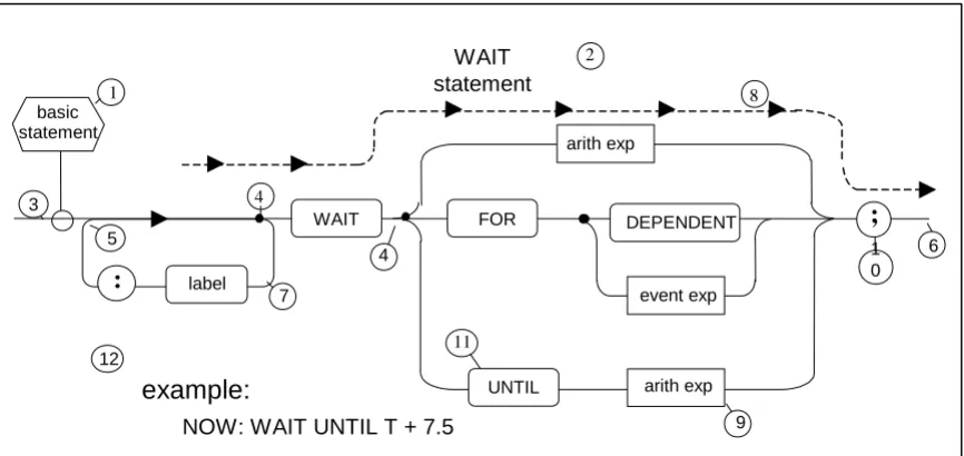
[image:21.612.91.524.419.624.2]A typical example of a syntax diagram is illustrated below. Following the diagram, a set of rules for reading it correctly is given. The rules apply generally to all syntax diagrams presented in the ensuing sections.
Figure 2-1 WAIT statement (typical syntax diagram) WAIT
statement 1
5
: label
basic statement
WAIT
4
FOR DEPENDENT
UNTIL
event exp
arith exp arith exp
;
7
6 1 0
9
example:
NOW: WAIT UNTIL T + 7.5
3
4
2
8
RULES:
1. Every diagram defines a syntactical term. The name of the term being defined appears in the hexagonal box . The title of the syntax diagram is usually a discursive description of the syntactical term. In the case illustrated, the language construct depicted is a particularization of the syntactical term defined (a “WAIT statement” is an example of ).
2. To generate examples of the construct, the flow path is to be followed from left to right, from box to box, starting at the point of juncture of the definition box , and ending when the end of the path is reached.
3. The path is moved along until it arrives at a black dot . No “backing up” along points of convergence such as is allowed. A black dot denotes that a choice of paths is to be made. The possible number of divergent paths is arbitrary.
4. Potentially infinite loops such as may sometimes be encountered. Sometimes there are semantic restrictions upon how many times such loops may be traversed. 5. Every time a box is encountered, the syntactical term it represents is added to the
right of the sequence of terms generated by moving along the flow path. For example, moving along the path paralleling dotted line generates the sequence “WAIT <arith exp>;” (see Rule 7).
6. Boxes with squared corners, such as , represent syntactical terms defined in other diagrams. Boxes with circular ends, such as , represent HAL/S primitives. Circular boxes, such as , contain special characters (see Section 2.2).
7. The text accompanying the syntax diagrams, boxes containing lower case names are represented by enclosing the names in the delimiters <>. Thus box becomes <arith exp>. Upper case names are reserved words of the language.
8. The example given at is an example of HAL/S code which may be generated by applying the syntax diagram (since some boxes, such as for example, are defined in other syntax diagrams, reference to them may be necessary to complete the generative process).
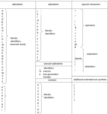
2.2 The HAL/S Character Set.
The HAL/S character set consists of the 52 upper and lower case alphabetical
characters, the numerals zero through nine, and other symbols. The restricted character set is the set necessary for the generation of constructs depicted by the syntax diagrams. The extended character set includes, in addition, certain other symbols legal in such places as comments and character literals, and is used chiefly for the purpose of compiler listing annotation.
The following table gives a complete list of the characters in the extended set, with a brief indication of their principal usage.
1
1
3
6
4
5
7
8
9
11
10
9
12
Figure 2-2 HAL/S character set 2.3 HAL/S Primitives.
HAL/S syntax diagrams ultimately express all syntactical elements in terms of a small number of special characters and pre-defined primitives. Primitives are constructed from the characters comprising the HAL/S restricted character set. There are three broad classes of primitives: “reserved words”, “identifiers”, and “literals”.
A B C D E F G H I J K L M N O P Q R S T U V W X Y Z a b c d e f g h i j k l m n o p q r s t u v w x y z + -* . / | & ¬ = < > # @ $ , ; : (blank) ( ) ' "
alphabetic alphabetic special characters
pseudo-alphabetic
2.3.1 Reserved Words.
As their names suggest, reserved words are names recognized to have standard meanings within the language and which are unavailable for any other use. With the exception of %macro names, they are constructed from alphabetic characters alone. Reserved words fall into three categories: keywords, %macro, and built-in function names. In the syntax diagrams, and in the accompanying text, reserved words are indicated by upper case characters. A list of keywords is given in Appendix B, and of built-in function names in Appendix C.
2.3.2 Identifiers.
An identifier is a name assigned by the programmer to be a variable, label, or other entity. Before its attributes are defined, it is syntactically known as an <identifier>. Each valid <identifier> must satisfy the following rules:
• the total number of characters must not exceed 32; • the first character must be alphabetic;
• any character except the first may be alphabetic or numeric;
• any character except the first or the last may be a “break character” (_).
The definition of an <identifier> generally establishes its attributes, and, in particular, its type. Thereafter, because its type is known, it is given one of the following names, as appropriate:
The manner in which its attributes are established is discussed in Section 4. The manner in which it is thereafter referenced is discussed in Section 5.
2.3.3 Numbers.
HAL/S supports two numeric types: INTEGER and SCALAR.
INTEGER type provides all the signed integers in some finite range. INTEGER DOUBLE supports a larger range than INTEGER single.
SCALAR type is represented as floating point numbers. As such they are an
approximation to the signed reals (engineering numbers) within some finite range and with some finite precision. SCALAR DOUBLE supports a larger range and/or greater precision than SCALAR single.
2.3.4 Literals.
Literals are groups of characters expressing their own values. During the execution of a body of HAL/S code their values remain constant. Differing rules apply for the formation of literals of differing type.
<label> ⎧arith (arithmetic) <process-event name> ⎪char (character) < § var name> where § ≡ ⎨bit
<template name> ⎪event
RULES FOR ARITHMETIC LITERALS:
1. No distinction is made between integer and scalar valued literals. They take on either integer or scalar type according to their context. Similarly, no distinction is made between single and double precision. Consequently, arithmetic literals can be represented by the single syntactical form <number>.
2. The generic form of a <number> is: ±dddddd.dddddddd<exponents> where d = decimal digit.Any number of decimal digits to an implementation
dependent maximum, including none, may appear before or after the decimal point. The sign and the decimal point are both optional. Any number of <exponents> to an implementation dependent maximum may optionally follow.
3. The form of the <exponents> may be: B<power> = 2<power> E<power> = 10 <power> H<power> = 16 <power>
where <power> is a signed integer number. The valid range of values of <power> is implementation dependent.
RULES FOR BIT LITERALS:
1. Literals of bit type are denoted syntactically by <bit literal>. 2. They have one of the forms shown below:
The <repetition> is optional and consists of a parenthesized positive integer number. It indicates how many times the following string is to be used in creating the value. The number of digits lies between 1 and an implementation dependent maximum. 3. The following abbreviated forms are allowed:
TRUE ≡ ON ≡ BIN ‘1’
FALSE ≡ OFF ≡ BIN ‘0’ examples:
0.123E16B-3 45.9
-4
BIN <repetition> ‘bbbbbbb’ where b = binary digit OCT <repetition> ‘ooooooo’ o = octal digit
HEX <repetition> ‘hhhhhhh’ h = hexadecimal digit
DEC ‘ddddddd’ d = decimal digit
examples:
BIN‘11011000110’
RULES FOR CHARACTER LITERALS:
1. Literals of character type are denoted syntactically by <char literal>. 2. They have one of the two following forms:
‘ccccccc’
CHAR <repetition> ‘ccccccc’
Where c is any character in the HAL/S extended character set. The <repetition> consists of a parenthesized positive integer literal. It indicates how many times the following string is to be used in creating the value. The number of characters lies between zero and an implementation dependent maximum.
3. A null character literal (zero characters long) is denoted by two adjacent apostrophes. 4. Since an apostrophe delimits the string of characters inside the literal, an apostrophe must be represented by two adjacent apostrophes; i.e., the representation of “dog’s” would be ‘DOG’ ‘S’.
5. Within a character literal, a special “escape” mechanism may be employed to indicate a character other than one in the HAL/S extended character set. “¢” is defined to be the “escape” character within this context. In accordance with an implementation dependent mapping scheme, HAL/S characters will be assigned alternate character values. Inclusion of these alternate values in a string literal is achieved by preceding the appropriate HAL/S character by the proper number of “escape” characters. The specified character with the “escape” character(s) preceding it will be interpreted as a single character whose value is defined by the implementation.
Since “¢” is used as the “escape” character, specification of the character “¢” as a literal itself must be done via the alternate character mechanism, i.e., an
implementation will designate an alternate value for some HAL/S character to be the character “¢”.
2.4 One- and Two-Dimensional Source Formats.
In preparing HAL/S source text, either single or multiple line format may be used. In the single line or “1-dimensional” format, exponents and subscripts are written on the same line as the operands to which they refer. In the multiple line or “2-dimensional” format, exponents are written above the line containing the operands to which they refer, and subscripts are written below it. Of the two formats, the 2-dimensional is considered standard since it closely parallels usual mathematical practice.
examples: ' '
'ONE TWO THREE' 'DOG''S'
'AB¢AD' 'AB¢¢AD'
⎤
RULES FOR EXPONENTS:
1. In the syntax diagrams, the 1-dimensional format is assumed for clarity. The operation of taking an exponent is denoted by the operator **.
2. Operations are evaluated right to left (see Section 6.1.1).
3. If an exponent is subscripted, the subscript must be written in the 1-dimensional format.
RULES FOR SUBSCRIPTS:
1. In the syntax diagrams, 2-dimensional format is assumed for clarity. Two special symbols are used to denote the descent to a subscript line, and the return from it:
Figure 2-3 Subscript Diagram
Effectively they delimit the beginning and end of a subscript expression, respectively. 2. The 1-dimensional format of a subscript expression consists of delimiting it at the
beginning by $( and at the end by a right parenthesis.
3. For certain simple forms of subscript, the parentheses may be omitted. These forms are:
• a single <number>
• a single <arith var name> (see Section 5).
4. If a subscript expression contains an exponentiation operation, the latter must be written in the 1-dimensional format.
examples: AJ→A**J AJK→A**J**K
examples:
AK+2 →A$(K+2)
examples: A →A$J
S descent to subscript line
2.5 Comments and Blanks in the Source Text.
Any HAL/S source text consists of sequences of HAL/S primitives interspersed with special characters. It is obviously of great importance for a compiler to be able to tell the end of one text element from the beginning of the next. In many cases the rules for the formation of the primitives are sufficient to define the boundary. In others, a blank character is required as a separator. Blanks are legal in the following situations:
between two primitives;
between two special characters;
between a primitive and a special character.
Blanks are necessary (not just legal) between two primitives. With respect to string (bit and character) literals, the single quote mark serves as a legal separator.
3.0 HAL/S BLOCK STRUCTURE AND ORGANIZATION
The largest syntactical unit in the HAL/S language is the “unit of compilation”. In any implementation, the HAL/S compiler accepts “source modules” for translation, and emits “object modules” as a result. Each source module consists of one unit of compilation, plus compiler directives for its translation.
At run time, an arbitrary number of object modules are combined to form an executable “program complex” 2. Generally, a program complex contains three different types of object modules:
• program modules - characterized by being independently executable.
• external procedure and function modules - characterized by being callable from other modules.
• compool modules - forming common data pools for the program complex. Each module originates from a unit of compilation of corresponding type. 3.1 The Unit of Compilation.
Each unit of compilation consists of a single PROGRAM, PROCEDURE, FUNCTION, or COMPOOL block of code, possibly preceded by one or more block templates.
Templates, in effect, provide the code block with information about other code blocks with which it will be combined in object module form at run time.
SYNTAX:
Figure 3-1 unit of compilation - #1 SEMANTIC RULES:
1. A program <compilation> is one containing a <program block>. Its object module in the program complex may be activated by the Real Time Executive (see Section 8), or by other means dependent on the operating system. The <program block> is described in Section 3.2.
2. A program complex is executable within the framework of an executive operating system, and a run time utility library.
compilation
function procedure compool program
1
procedure block program template
program block compool block function block §
§
function template
procedure template
2. A procedure or function <compilation> is one containing a <procedure block> or <function block>, respectively. Its object module in the program complex is executed by being invoked by other program, procedure, or function modules. Both
<procedure block>s and <function block>s are described in Section 3.3.
3. A compool <compilation> is one containing a <compool block> specifying a common data pool potentially available to any program, procedure, or function module in the program complex. The <compool block> is described in Section 3.5.
4. The code block in any <compilation> except a compool <compilation> may contain references to data in a compool <compilation>, references to other <program
block>s, and invocations of external <procedure block>s or <function block>s in other <compilation>s. A <compilation> making such references must precede its code block with a block template for each <program block>, <procedure block>, <function block>, or <compool block> referenced. Block templates are described in Section 3.6.
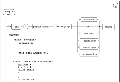
3.2 The PROGRAM Block.
[image:30.612.113.501.360.624.2]The PROGRAM block delimits a main, independently executable body of HAL/S code. SYNTAX:
Figure 3-2 PROGRAM block - #2
Program block
example:
2
:
label
statement
program header declare group
task block
procedure block function block
closing
DECLARE Q; .
. .
CALL BETA ASSIGN(Q);
.
.
.
BETA: PROCEDURE ASSIGN(W); DECLARE W;
W = W + 1; CLOSE BETA; .
. .
CLOSE ALPHA;
update block
SEMANTIC RULES:
1. The name of the <program block> is given by the <label> prefacing the block.
2. The <program block> is delimited by the <program header> statement at beginning, and a <closing> at the end. These two delimiting statements are described in
Sections 3.7.1 and 3.7.4, respectively.
3. The contents of a <program block> consists of a <declare group> used to define data local to the <program block>, followed by any number of executable <statement>s. 4. The normal flow of execution of the <statement>s in the block is sequential; various
types of <statement> may modify this normal sequencing in a well-defined way. 5. PROCEDURE, FUNCTION, TASK, and UPDATE blocks may appear nested within a
<program block>. The blocks may be interspersed between the <statement>s of the <program block>, and with the exception of the UPDATE block are not executed in-line.
6. Execution of a <program block> is accomplished by scheduling it as a process under control of the Real Time Executive (see Section 8).
3.3 PROCEDURE, FUNCTION, and TASK Blocks.
PROCEDURE, FUNCTION, and TASK blocks share a common purpose in serving to structure HAL/S code into an interlocking modular form. The major semantic distinction between the three types of block is the manner of their invocation.
SYNTAX:
Figure 3-3 PROCEDURE, FUNCTION, TASK block - #3 SEMANTIC RULES
1. The name of the block is given by the <label> prefacing the block. The definition of a block label is considered to be in the scope of the outer block containing the block in question. Block names must be unique within any compilation unit.
2. The block is delimited at its beginning by a header statement characteristic of the type of block, and at the end by a <closing>. The delimiting statements are described in Sections 3.7.1 through 3.7.4.
3. The contents of a block consists of a <declare group> used to declare data local to
3
block
PROCEDURE FUNCTION TASK
block
:
label
statement
header declare group
function block update block
closing
procedure block example:
NEW: TASK; I = 1; CLOSE NEW;
the block, followed by any number of executable <statement>s.
4. The normal flow of execution of the <statement>s in the block is sequential; various types of <statement> may modify this normal sequence in a well-defined way.
5. The block may contain further nested PROCEDURE, FUNCTION, and UPDATE blocks. An UPDATE block may not appear within an UPDATE block at any level of nesting. The nested blocks may appear interspersed between the <statement>s of the outer block, and except for the UPDATE block are not executed in-line. A
consequence of this rule is that PROCEDURE and FUNCTION blocks may be nested within each other to an arbitrary depth.
6. The execution of a <task block> is invoked by scheduling it as a process under the control of the Real Time Executive (see Section 8). Execution of a <procedure block> is invoked by the CALL statement (see Section 7.4). Execution of a <function block> is invoked by the appearance of its name in an expression (see Section 6.4).
7. A <procedure block> or <function block> may result in either a single out-of-line expansion or an in-line expansion at each invocation. The semantics of a block invocation is independent of the way it is expanded.
8. A <task block> may not appear within a DO...END group.
9. In the <declare group> of a PROCEDURE or FUNCTION block which forms the outermost code block of a <compilation unit>, some implementations may require all formal parameters to be declared before any local data.
3.4 The UPDATE Block.
The UPDATE block is used to control the sharing of data by two or more real time processes. Its functional characteristics in this respect are described in Section 8. SYNTAX:
Figure 3-4 UPDATE block - #4 SEMANTIC RULES:
1. If present, the <label> prefacing the <update block> gives the name of the block. If <label> is absent, the <update block> is unnamed.
4
update block
statement
update header declare group closing
function block label :
2. The block is delimited at its beginning by an <update header> statement, and at the end by a <closing>. The delimiting statements are described in Sections 3.7.1 and 3.7.4.
3. The contents of the block consist of a <declare group> used to declare data local to the <update block>, followed by any number of executable <statement>s.
4. The normal flow of execution of the <statement>s in the block is sequential; various types of <statement>s may modify this normal sequencing in a well defined way. 5. Only PROCEDURE and FUNCTION blocks may be nested within an <update block>.
The nested blocks may appear interspersed between the <statement>s of the block, and are not executed in-line.
6. An <update block> is treated like a <statement> in that it is executed in-line. In this respect it is different from other code blocks.
7. The following <statement>s are expressly forbidden inside an <update block> in view of its special protective function:
• I/O statements (see Section 10);
• invocations of <procedure block>s or <function block>s not themselves nested within the <update block>;
• real-time programming statements, except for the SIGNAL, SET, and RESET statements (see Section 8.8).
3.5 The COMPOOL Block.
The COMPOOL block specifies data in a common data pool to be shared at run time by a number of program, procedure, and function modules.
SYNTAX:
Figure 3-5 COMPOOL block - #5 SEMANTIC RULES:
1. The name of the block is given by the <label> prefacing the block.
2. The block is delimited at its beginning by a <compool header> statement, and at its end by a <closing>. The delimiting statements are described in Sections 3.7.1 and 3.7.4.
3. The contents of the block consist merely of a <declare group> used to define the data constituting the compool. In no sense is a <compool block> to be regarded as an executable body of code.
5
compool block
4. The maximum number of <compool block>s existing in a program complex is implementation dependent.
3.6 Block Templates.
In a <compilation>, block templates are used to provide the outermost code block of the <compilation> with information concerning external code or data blocks. Depending upon the implementation, the translation of program, procedure, function, and compool <compilation>s may automatically generate the corresponding block templates, to be included in other <compilation>s by compiler directive.
There are four kinds of block templates, PROGRAM, PROCEDURE, FUNCTION, and COMPOOL templates, all being syntactically similar (see Section 3.1).
SYNTAX:
Figure 3-6 PROGRAM, PROCEDURE, FUNCTION, COMPOOL template - #6 SEMANTIC RULES
1. The <label> of the template constitutes the template name. It is the same name as that of the code block to which the template corresponds.
2. The block template is delimited at its beginning by a header statement identical with the header statement of the corresponding code block, and at the end by a <closing>. The delimiting statements are described in Sections 3.7.1 and 3.7.4.
3. The contents of the block template consist only of a <declare group>, which has the following significance:
• in a program <template>, the <declare group> contains no statements. All information about external programs is contained in the <program header>; • in a <compool template>, the <declare group> is used to declare a common data
pool identical with that of the corresponding <compool block>;
• in a <procedure template> or <function template>, the <declare group> is used to declare the formal parameters of the corresponding <procedure block> or <function block> (see Sections 3.7.2 and 3.7.3).
4. The keyword EXTERNAL preceding the header statement of the block template distinguishes it from an otherwise identical code block. To a HAL/S compiler the keyword is in effect a signal to prevent the compiler from generating object code for the block and setting aside space for the data declared.
6
template
PROGRAM PROCEDURE FUNCTION COMPOOL
template
:
label header declare group closing
example:
ETA: EXTERNAL COMPOOL; DECLARE S SCALAR; CLOSE ETA;
EXTERNAL
§ §
3.7 Block Delimiting Statements.
Both code blocks and block templates are delimited at the beginning by a header statement characteristic of their type, and at the end by a <closing> statement. In all code blocks except for the COMPOOL block, the header statement is the first statement of the block to be executed upon entry. A COMPOOL block, containing only declarations of data, is, of course, not executable at all.
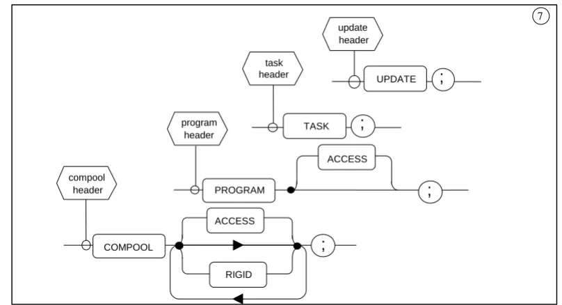
3.7.1 Simple Header Statements
[image:35.612.102.506.253.472.2]Simple header statements are those which specify no parameters to be passed into or out of the block. They are the compool, program, task, and update header statements. SYNTAX:
Figure 3-7 COMPOOL, PROGRAM, TASK, UPDATE header statement - #7 SEMANTIC RULES:
1. The type of the code block or template is determined by the type of the header statement, which is in turn indicated by one of the keywords COMPOOL,
PROGRAM, TASK, and UPDATE.
2. The keyword ACCESS causes managerial restrictions to be placed upon the usage of the block in question. The manner of enforcement of the restriction is
implementation dependent.
3. The keyword RIGID causes COMPOOL data (except for data with the REMOTE attribute) to be organized in the order declared and not rearranged by the compiler.
7
; UPDATE task
header
; TASK
; PROGRAM
ACCESS
; COMPOOL
ACCESS
RIGID program
header
update header
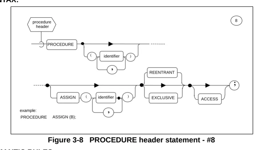
3.7.2 The Procedure Header Statement.
The procedure header statement delimits the start of a <procedure block> or <procedure template>.
[image:36.612.94.510.144.387.2]SYNTAX:
Figure 3-8 PROCEDURE header statement - #8 SEMANTIC RULES:
1. The keyword PROCEDURE identifies the start of a <procedure block> or <procedure template>. It is optionally followed by lists of “formal parameters” which correspond to “arguments” in the invocation of the procedure by a CALL statement (see Section 7.4).
2. The <identifier>s in the list following the PROCEDURE keyword are called “input parameters” because they may not appear in any context inside the code block which may cause their values to be changed.
3. The <identifier>s in the list following the ASSIGN keyword are called “assign
parameters” because they may appear in contexts inside the code block in which new values may be assigned to them. They may, of course, also appear in the same contexts as input parameters.
4. Data declarations for all formal parameters must appear in the <declare group> of the <procedure block> or <procedure template>.
5. If the <procedure header> statement specifies neither of the keywords REENTRANT or EXCLUSIVE, then only one real time process (see Section 8) may be executing the <procedure block> at any one time; however, there is no enforcing protective mechanism. If the keyword EXCLUSIVE is specified, then such a protective mechanism does exist. If an EXCLUSIVE <procedure block> is already being
executed by a real time process when a second process tries to invoke it, the second process is forced into the stall state (see Section 8) until the first has finished
executing it. If the keyword REENTRANT is specified, then two or more processes
identifier PROCEDURE
) (
,
) ( identifier
,
ASSIGN EXCLUSIVE ACCESS
;
REENTRANT
8
example:
PROCEDURE ASSIGN (B); procedure
6. The keyword REENTRANT indicates to the compiler that reentrancy is desired. However, other attributes and conditions may conflict with this overall objective. The following effects should be noted:
• STATIC data is allocated statically and initialized statically. There is only one copy of static data which must be shared by all processes simultaneously executing the block. Hence, in coding REENTRANT blocks care must be taken not to assume that STATIC variables participate in the reentrancy.
• AUTOMATIC data is allocated dynamically and initialized dynamically. Every process simultaneously executing the block gets its own initialized copy of the data on entry into the block. In general, all local data in a REENTRANT block should be declared with the AUTOMATIC attribute.
• Procedures and functions defined within a REENTRANT block must also possess the REENTRANT attribute if they, too, declare local data which is required to participate in the reentrancy.
In addition, for reentrancy to be preserved, the following rules must be observed: • Update blocks3 and inline functions within a REENTRANT block may not declare
any local data, STATIC or AUTOMATIC, because the update block does not inherit the reentrant attribute from the enclosing procedure declaration;
• A procedure or function called by a REENTRANT block must itself also be REENTRANT.
7. The keyword ACCESS may be attached to the <procedure header> of a <procedure template> and its corresponding external <procedure block>. It denotes that
managerial restrictions are to be placed on which <compilation>s may reference the <procedure block>. The manner of enforcement is implementation dependent. 3.7.3 The Function Header Statement.
The function header statement delimits the start of a <function block> or <function template>.
SYNTAX:
Figure 3-9 FUNCTION header statement - #9
3. Any use of update blocks and LOCK data, or of EXCLUSIVE procedure or function blocks should be carefully analyzed with respect to unfavorable timing problems if a procedure is reentered by a higher priority process.
identifier FUNCTION
) (
,
ACCESS
;
9
example:
FUNCTION(A) SCALAR REENTRANT;
function header
REENTRANT EXCLUSIVE type
SEMANTIC RULES:
1. The keyword FUNCTION identifies the start of a <function block> or <function template>. It is optionally followed by a list of “formal parameters” which are substituted by corresponding “arguments” in the invocation of the <function block> (see Section 6.1.1).
2. The <identifier>s in the list following the FUNCTION keyword are “input parameters” since they may not appear in any context inside the <function block> which may cause their values to be changed.
3. Data declarations for all the formal parameters must appear in the <declare group> of the <function block> or the <function template>.
4. <type spec> identifies the type of the <function block> or <function template>. A <function block> may be of any type except EVENT. The formal description of the type specification given by <type spec> is given in Section 4.7.
5. If the <function header> statement specifies neither of the keywords REENTRANT or EXCLUSIVE, then only one real time process (see Section 8) may be executing the <function block> at any one time; however, there is no enforcing protective
mechanism. If the keyword EXCLUSIVE is specified, then such a protective
mechanism does exist. If an EXCLUSIVE <function block> is already being executed by a real time process when a second process tries to invoke it, the second process is forced into the stall state (see Section 8) until the first has finished executing it. If the keyword REENTRANT is specified, then two or more processes may execute the <function block> “simultaneously”.
6. The keyword REENTRANT indicates to the compiler that reentrancy is desired. However, other attributes and conditions may conflict with this overall objective. The following effects should be noted:
• STATIC data is allocated statically and initialized statically. There is only one copy of STATIC data which must be shared by all processes simultaneously executing the block. Hence, in coding REENTRANTblocks, care must be taken not to assume that STATIC variables participate in the reentrancy.
• AUTOMATICdata is allocated dynamically and initialized dynamically. Every
process simultaneously executing the block gets its own initialized copy of the data on entry into the block. In general, all local data in a REENTRANTblock should be declared with the AUTOMATIC attribute.
• Procedures and functions defined within a REENTRANT block must also possess the REENTRANT attribute if they, too, declare local data which is required to participate in the reentrancy.
In addition, for reentrancy to be preserved, the following rules must be observed: • Update blocks4 and inline functions within a REENTRANTblock may not declare
any local data, STATIC or AUTOMATIC, because the update block does not inherit the reentrant attribute from the enclosing function declaration;
• A procedure or function called by a REENTRANT block must itself also be REENTRANT.
7. The keyword ACCESS may be attached to the <function header> of a <function template> and its corresponding external <function block>. It denotes that
managerial restrictions are to be placed on which <compilation>s may reference the <function block>. The manner of enforcement is implementation dependent.
3.7.4 The CLOSE Statement.
For all code blocks, COMPOOL blocks, and block templates, the CLOSE statement is the <closing> delimiter of the block.
SYNTAX:
Figure 3-10 closing of block - #10 SEMANTIC RULES:
1. The <closing> of a code block or block template is denoted by the CLOSE keyword followed by an optional <label>. If present, <label> must be the name of the block. 2. Execution of the CLOSE statement causes a normal exit from a PROGRAM,
PROCEDURE, TASK, or UPDATE block, and a run time error from a FUNCTION block. Exit from a function block must be achieved via the RETURN statement (see Section 7.5).
3. The <closing> of a COMPOOL or PROGRAM block template or a PROGRAM, COMPOOL, PROCEDURE, FUNCTION, TASK, or UPDATE block may be labeled as if it were a <statement>. The <closing>s of PROCEDURE and FUNCTION block templates cannot be labeled.
3.8 Name Scope Rules.
By using the code blocks described, and by taking advantage of their nesting property, the modularization of HAL/S <compilation>s may be achieved. An important
consequence of the nesting property is the need to determine the “name scope” over which names defined in a code block are potentially known. Names (i.e., <identifier>s) to which name scope rules apply are generally either labels or variable names.
10
:
CLOSE
label
;
example:
ALL_DONE: CLOSE; label
GENERAL RULES:
[image:40.612.101.465.397.671.2]QUALIFICATIONS:
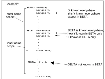
Figure 3-11 Name Scope Examples
1. The name scope of a code block encompasses the entire contents of a block, including all blocks nested within it.
2. The name defined in a name-scope is known, and therefore able to be referenced, throughout that name-scope, including all nested blocks not redefining it. A name defined in a scope is not known outside that name-scope.
3. Names defined in all common data pools used by a <compilation> are considered to be defined in one name-scope which encloses the outermost code block of the <compilation>.
1. The name of a code block is taken to be defined in the name-scope immediately enclosing the block. A PROCEDURE or FUNCTION defined at the outermost level of compilation can be invoked from anywhere within the compilation.
2. The <label> of a statement is effectively unknown in blocks contained in the name scope where the <label> is defined. This is because a code block cannot be branched out of by using a GO TO statement (see Section 7.7).
3. Block labels must be unique throughout a unit of compilation.
4. Under particular, limited circumstances described in Section 4.3, the names of structure template nodes and terminals need not be unique.
example: outer name scope: inner name scope: ALPHA: PROGRAM; DECLARE X; DECLARE Y; . . . . .
BETA: PROCEDURE; DECLARE Y; DECLARE Z; . . . . CLOSE BETA; . . . DELTA: Y = 0;
. . . .
CLOSE ALPHA;
X known everywhere this Y known everywhere except in BETA.
BETA is known everywhere; new Y known in BETA only Z known in BETA only
4.0 DATA AND OTHER DECLARATIONS
The HAL/S language provides a comprehensive set of data types. To encourage clarity and decrease the frequency of errors of omission, all data is required to be declared in specific areas of a HAL/S compilation called “declare groups”. Occasionally the
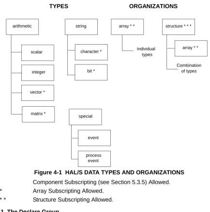
[image:41.612.81.515.176.613.2]demands of a particular algorithm also require other kinds of declarations to be made. Figure 4-1 summarizes the relationship among the types and organizations.
Figure 4-1 HAL/S DATA TYPES AND ORGANIZATIONS * Component Subscripting (see Section 5.3.5) Allowed. * * Array Subscripting Allowed.
* * * Structure Subscripting Allowed. 4.1 The Declare Group.
A <declare group> is a collection of data and other declarations. The position of
<declare group>s within code blocks and block templates has been described in Section 3.
TYPES ORGANIZATIONS
arithmetic string array * * structure * * *
character *
special scalar
vector *
matrix *
integer bit *
array * *
process event event
individual types
SYNTAX:
Figure 4-2 declare group - #11 SEMANTIC RULES:
1. A <declare group> may simply be empty, or it may contain <replace statement>s, <structure template>s, and <declare statement>s. The form of each of these constructs is defined in this Section.
2. The “name scope” (see Section 3.8) of <identifier>s defined in a <declare group> is the code block containing the <declare group> and potentially all code blocks nested within it.
4.2 The REPLACE Statement.
The REPLACE statement is used to define an identifier text substitution which is to take place wherever the identifier is referenced within the same name scope after its
definition. The REPLACE statement constitutes a “source macro” definition. 4.2.1 Form of REPLACE Statement.
SYNTAX:
Figure 4-3 replace statement - #12
11
declare statement declare
group
replace statement
structure template
example:
REPLACE ALPHA BY "J+1" ;
REPLACE BETA (X, ANGLE) BY "SIN (X ANGLE) - EXP (X) / X" ;
) (
"
;
12
,
identifier REPLACE
BY
identifier
text Replace
statement
GENERAL SEMANTIC RULES:
1. The <identifier> following the keyword REPLACE is called the REPLACE name. 2. A REPLACE name may not appear as a formal parameter in a <procedure header> or
<function header>.
3. A REPLACE name in an inner code block is never “replaced” as a result of another REPLACE statement located in an outer code block.
4. Nested replacement operations to some implementation dependent depth are allowed (i.e., the <text> of a <replacement statement> may contain a further <identifier> to be replaced).
SEMANTIC RULES: Simple Replacements
1. A simple replacement is a REPLACE statement with no parameter list following the <identifier>.
2. Whenever it is referenced, an <identifier> defined in a simple REPLACE statement is to be replaced by <text> of the definition as if <text> had been written directly instead of the source macro reference. Enclosing the reference within ¢ signs (e.g.,
¢ALPHA¢) makes the <text> visible in the compiler listing.
3. <text> may consist of any HAL/S characters except instances of an unpaired double quote (“) character. A double quote character (”) is indicated within the <text> by two such characters in succession (“”).
SEMANTIC RULES: Parametric Replacements
1. A parametric replacement is defined by a REPLACE statement with a list of one or more parameters following the <identifier>. The maximum number of parameters allowed is an implementation dependent limit. Each parameter is itself a HAL/S <identifier>. It is known only locally to the REPLACE statement: its name may therefore be duplicated by names used for other <identifier>s in the name scope containing the REPLACE statement.
2. The <text> of a parametric REPLACE statement is composed of any HAL/S characters except instances of an unpaired double quote (“) character. A double quote character may be indicated within <text> by coding two such characters in succession. The <text> may contain, but is not required to contain, instances of the parameters of the REPLACE statement.
4.2.2 Referencing REPLACE Statements. SYNTAX:
Figure 4-4 parametric replace reference - #12.1
identifier
,
argument ) (
12.1 parametric
SEMANTIC RULES:
1. A reference to a parametric REPLACE statement consists of the REPLACE name followed by a series of <argument>s enclosed in parentheses. The REPLACE name must have been defined previously within the name scope of the reference. The number of <argument>s must correspond to the number of parameters of the
REPLACE statement being referenced. Enclosing the reference within ¢ signs (e.g., ¢CBETA(A,B)¢) makes the <text> visible in the compiler listing.
2. The <argument>s supplied in a parametric REPLACE reference are substituted for each occurrence of the corresponding parameter within the source macro definitions <text>. Note that if the parameter in question does not occur within the source macro definition’s <text>, the <argument> is ineffective. <text> substitution is always
completed before parsing. Example:
REPLACE BETA(X,ANGLE) BY “SIN(X ANGLE) - EXP(X)/X”; .
. .
Z = BETA(Y,ALPHA); WILL GENERATE SIN(Y ALPHA) - EXP(Y)/Y
3. In general, the <argument>s supplied in a parametric REPLACE reference comprise <text> separated by commas (subject to the specific exceptions listed below). As such, they conform to the preceding semantic rules for <text> with the following emendations:
• Blanks are significant in <argument>s. Only the commas used to separate <argument>s are excluded from the <text> values substituted into the macro definition.
• The <text> string comprising an <argument> may be empty. The value substituted in such a case is a null string.
• Within each <argument> there must be an even number of apostrophe characters (’). The effect of this rule is to require that each character literal used must be completely contained within a single <argument>.
• Within each <argument> there must be an even number of quotation mark
characters (“). The effect of this rule is to require that the substitution of a nested REPLACE statement include the entire text of the replacement within a single <argument>.
• Within each <argument> there must be a balanced number of left and right
parentheses: for each opening left parenthesis there must be a corresponding right parenthesis.
• Commas are not separators between <argument>s under the following circumstances:
4.2.3 Identifier Generation
New identifiers may be generated by enclosing a reference to a simple REPLACE statement within ¢ signs. The effect is to make visible in the compiler listing, the catenation of the REPLACE <text> with the characters surrounding the construct. For example, REPLACE ABLE BY “BAKER”; then:
1. X = ¢ABLE¢YZ becomes X = BAKERYZ
2. CALL P_¢ABLE¢(Q,R,S); becomes CALL P_BAKER(Q,R,S); ¢ signs are taken in pairs, thus ¢X¢Y¢Z¢ is interpreted as ¢X¢Y¢Z¢. 4.2.4 Identifier Generation With Macro Parameters.
New identifiers may be generated for text substitution within a source macro text by enclosing references to macro parameters within ¢ signs. The effect is the compile-time catenation of the corresponding macro arguments with the characters surrounding the ¢-enclosed parameter (a blank is considered as a character). For example:
Figure 4-5 Creating Identifiers With Replace Macros
Enclosing the entire reference with ¢ signs, i.e., ¢ABLE(V, A)¢ makes the text with the new identifiers visible in the compiler listing (see Section 4.2.2).
4.3 The Structure Template.
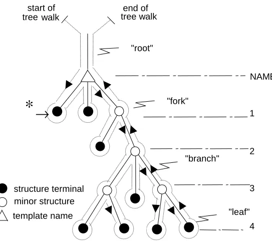
In HAL/S, a “structure” is a hierarchical organization of generally nonhomogeneous data items. Conceptually, the form of the organization is a “tree”, with a “root”, “branches”, and with the data as “leaves”. The definition of the “tree organization” (the manner in which the root is connected to the branches, and branches to leaves) is separate from the declaration of a structure having that organization. The tree organization is defined by a <structure template> described below. The description of the declaration of
structures is deferred to later subsections.
The following figure represents a typical tree organization. REPLACE ABLE(X,Y) BY
“P = ¢X¢QRS+Y;
CALL SUB_¢X¢; ”;
Then the reference ABLE (V, A) causes the following substitutions. P = VQRS+A;
Figure 4-6 Tree diagram for a typical structure template INTERPRETATIONS:
1. The “template name” is at the root of the tree organization.
2. The named “leaves” and “forks” in the branches are at numbered levels below the root. Leaves and forks are called “structure terminals” and “minor structures”, respectively.
3. The “tree walk” shown can provide an unambiguous linear description of the tree organization. The syntactical form of the <structure template> corresponding to a tree organization calls for the names of minor structures and structure terminals to be defined in the same order that the tree walk passes them on the left, as indicated by the arrow at * in the diagram.
4. The tree organization of two templates are considered to be equivalent for the
purposes of various HAL/S statement contexts only if the tree forms are identical, and the type and attributes of all nodes in the tree agree. An implication of this rule becomes apparent: if two corresponding terminal nodes of otherwise equivalent structures reference different structure template names, then the structure templates containing these terminal nodes are not identical.
∗
→
structure terminal minor structure template name
start of tree walk
end of tree walk
"root"
"fork"
"branch"
"leaf" NAME
1
2
3
The syntactical form of a <structure template> is now given: SYNTAX:
Figure 4-7 structure template statement - #13 GENERAL RULES:
1. The <template name> of the <structure template> is given by the <identifier> following the keyword STRUCTURE.
2. The operational keywords DENSE and ALIGNED denote data packing attributes to be applied to all <identifiers> declared with the <structure template>. At each level of a <structure template>, either the DENSE or ALIGNED packing attribute is in effect, subject to modification by use of DENSE and ALIGNED as minor <attributes>. The choice used in the <structure template> gives the default value for the whole
template. This packing attribute is then inherited from higher to lower levels in the structure unless the <attributes> of a minor structure or terminal element modify the choice. Details of the allocation algorithm used for DENSE and ALIGNED data are implementation dependent.
3. The keyword RIGID causes data to be in the sequential order declared within the <structure template>. This attribute is then inherited from higher to lower levels in the structure. Details of the allocation algorithm used for RIGID are implementation dependent. Note that the absence of the keyword RIGID permits compiler reorganization of data.
4. In each definition, <number> is a positive integer specifying the level of the tree at which the definition is effective. Numbering is sequential starting with 1.
5. The level of definition in conjunction with the order of definition is sufficient to distinguish between a minor structure and a structure terminal.
6. In the form <identifier> <attributes>, <identifier> is the name of the minor structure or structure terminal defined. The applicable <attributes> are described in Section 4.5. 7. If the <attributes> specify a structure template <type spec> (see Section 4.7), then the
template of the structure is being included as part of the template being defined. 8. The minor structures and structure terminals of the template (the forks and leaves) are
structure template
STRUCTURE :
13
identifier
RIGID DENSE
ALIGNED
identifier
number attributes ;
15
sequentially defined following the colon. The order of definition has already been described.
9. Each definition of a minor structure of structure terminal is separated from the next by a comma.
NAME UNIQUENESS RULES:
1. <template names> may duplicate <identifiers> of any other kind within a given name scope, but may not duplicate other <template names>.
2. In a given name scope, if a <template name> is used exclusively in qualified structure declarations, duplications of the <identifiers> used for nodes may occur under the following circumstances:
• Any <identifier> used for a node in one template may duplicate an <identifier> used for a node in another template.
• Any <identifier> used for a node in a given template may duplicate another
<identifier> used for a different node in the same template, provided that a qualified reference can distinguish the two nodes.
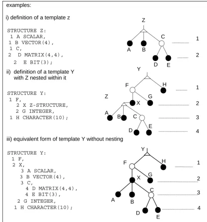
Figure 4-8 structure template examples C
H H F
i) definition of a template z
STRUCTURE Z: 1 A SCALAR, 1 B VECTOR(4),
1 C,
2 D MATRIX(4,4),
2 E BIT(3);
ii) definition of a template Y with Z nested within it
STRUCTURE Y: 1 F,
2 X Z-STRUCTURE, 2 G INTEGER, 1 H CHARACTER(10);
iii) equivalent form of template Y without nesting
STRUCTURE Y: 1 F,
2 X,
3 A SCALAR, 3 B VECTOR(4),
3 C,
4 D MATRIX(4,4), 4 E BIT(3), 2 G INTEGER, 1 H CHARACTER(10);
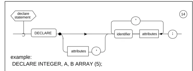
4.4 The DECLARE Statement.
The DECLARE statement is used to declare data names and labels, and to define their characteristics or <attributes>.
[image:50.612.117.488.158.294.2]SYNTAX:
Figure 4-9 declaration statement - #14 SEMANTIC RULES:
1. Each <identifier> and its following <attributes> constitute the declaration of a data name or label. Each definition is separated from the next by a comma.
2. The generic characteristics, if any, of all <identifier>s to be declared are given by the “factored” <attributes> immediately following the keyword DECLARE. The
<attributes> of a particular <identifier> must not conflict with the factored <attributes>. 3. The name scope of any of the <identifier>s defined in a <declare statement> is the
code block containing the <declare group> of which the <declare statement> is a part (see Section 3.8). In any name scope all such <identifiers> must be unique.
4. There are two forms of <attributes>::: data declarative, and label declarative. The form determines whether an <identifier> is defined as a data name or a label. 4.5 Data Declarative Attributes.
Data declarative attributes are used to define an <identifier> to be a data name or part of a structure template, and to describe its characteristics. If <attributes> appear in a <declare statement>, the <identifier> defined is a “simple variable”, or a “major structure” with a predefined template. If <attributes> appear in a <structure template>, the
<identifier> defined is either a minor structure, or a structure terminal. Structure terminals have very similar properties to simple variables.
14 declare
statement
attributes
,
,
example:
DECLARE INTEGER, A, B ARRAY (5);
SYNTAX:
Figure 4-10 data declarative attributes - #15 GENERAL SEMANTIC RULES:
1. The <type spec> determines the type and possibly the precision of the <identifier> to which the <attributes> are attached. Type specifications are discussed in Section 4.7.
2. An optional array specification can precede the <type spec>. It starts with the keyword ARRAY; the following parenthesized list specifies the number of dimensions in the array, and the size of each dimension. The number N of <arith exp>s gives the number of dimensions of the array. <arith exp> is an unarrayed integer or scalar expression computable at compile time5. The value is rounded to the nearest integer, and indicates the number of elements in a dimension. Its value must lie between 2
5. See Appendix F. example:
ARRAY(5) SCALAR STATIC
initialization ALIGNED REMOTE
ACCESS DENSE STATIC
LOCK
RIGID
LATCHED number attributes
arith exp ARRAY
type spec
)
*
( )
,
17 15
18
*
AUTOMATIC