Different Methods for Enhancing
Power Quality
Amardeep Sharma1, Dr. Babita Jain2
1
Student, Department of Electrical Engineering, Poornima College of Engineering,Jaipur
2
Assistant Professor, Department of Electrical Engineering, Poornima College of Engineering, Jaipur
Abstract: Current power utilities need to react to various difficulties, for example, development of power request particularly in non-straight loads in power networks, therefore, a few arrangements about the power with a higher quality ought to be considered.
This paper manages applied investigation of intensity quality upgrades techniques used to moderate the voltage list, swell, voltage plunge concealment and expulsion of sounds mutilation like UPFC (Unified Power Flow Controller)which attempts to improve the power quality at interest side by power conditionings for consonant end and concurrent remuneration of voltage and current, which improves the power quality offered for other symphonious delicate burdens, DPFC (Distributed power stream controller) is utilized to relieve the voltage deviation and improve control quality. (UPQC) bound together power quality conditioner for consonant disposal and synchronous remuneration of voltage and current, which improves the power quality offered for other symphonious touchy burdens.
DSTATCOM (Static Synchronous Reactive Compensator) is a shunt associated compensator to retain or supply responsive current against voltage unsettling influences, for example, voltage droop, swell and gleam. DVR (Dynamic Voltage Restorer) is utilized for improving force quality and diminish the sounds contortion of touchy burden. DVR Proposed not exclusively to improve PQ yet in addition to diminish HD because of the nearness of non-straight burden. Consolidated framework developed by Shunt Active Power Filter (SAPF) and Static Var Compensator (SVC) to improve the power Quality of the island microgrid, in which SAPF utilizes the positive succession technique for consonant identification.
Keywords: Power enhancement, Power quality, Techniques for power management
I. INTRODUCTION
Because of Power quality issues a wide scope of aggravations like voltage swells/droops, gleam, sounds, contortion, motivation homeless people and intrusions are happened. Voltage swells are not as critical as voltage droops since they are less basic in appropriation frameworks.
Voltage list and swell can make delicate gear come up short or shut down, just as make a huge current unbalance that could blow wires or outing breakers. These impacts can be over the top expensive for the clients, going from minor quality varieties to creation downtime and gear harm. Voltage droops can happen at any moment of time, with sufficiency running from 10-90 % and term going on for a large portion of a cycle to one moment .Voltage swell, then again is characterized as swell is characterized as an expansion in rms voltage or current at power recurrence for lengths from 0.5 cycles to one moment. The run of the mill voltage infusion capacity of a DVR is in the scope of half. Henceforth, to make up for music as low as 1% (or lower) the framework must work at adjustment profundities of around 2%; however high size and stage precision should even now be kept up for the remuneration to be compelling. Late work (Metin Kesler et al,2009 ) has proposed a feed-forward methodology for voltage consonant remuneration that additionally represents the example deferral and voltage drop over the channel inductance (Metin Kesler et al,2009 ).
There are a wide range of strategies to alleviate voltage lists and swells yet the utilization of a custom power gadget is viewed as the most proficient strategy. Numerous custom power controllers have just been talked about with delicate loads under anomalous conditions. A large number of these power controller gadgets we have talked about beneath to think about the voltage quality as far as droop, swells and gleams and to improve nature of current at utility end with the assistance of their designs and working standards. To tackle this issue, custom power gadgets are utilized utilizing MATLAB for static and dynamics.
Figure 1: Schematic diagram of DVR
1) DVR is an arrangement associated gadget intended to keep up a consistent RMS voltage over a touchy burden. The DVR comprises of:-
a) An infusion/arrangement transformer.
b) A symphonious channel.
c) A Voltage Source Converter (VSC).
d) An vitality stockpiling
e) A control framework
Schematic graph of DVR is appeared in fig. The primary capacity of a DVR is the assurance of touchy burdens from voltage lists/swells originating from the system. In the event that a blame happens on different lines, DVR embeds arrangement voltage VDVR and remunerates load voltage to pre blame esteem .
Dynamic Voltage Restorers (DVR) are presently winding up progressively settled in industry to lessen the effect of voltage lists to delicate burdens . Be that as it may, since voltage lists commonly just happen a couple of times every year at a specific area, DVR framework will by and large invest the majority of its energy in reserve mode trusting that hang will happen. Be that as it may, tragically, it will even now acquaint additional impedance with the line, essentially because of the arrangement transformer and this impedance will thus cause a voltage drop to the heap and expanded burden voltage music when non-direct loads are available (Sandesh Jainet al,2012 ). On a fundamental level, it would be profitable if the arrangement associated inverter of the DVR could likewise be utilized to make up for any consistent state load voltage sounds (Sandesh Jainet al,2012 ). This would expand the Power Quality 'esteem included' advantages to the framework (which is the definition and main impetus of Custom Power Applications) with insignificant
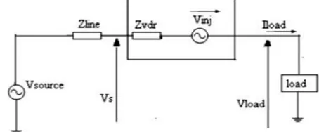
Figure 2: Typical DVR series connected topology (Sandesh Jainet al,2012 )
[image:2.612.187.414.466.560.2]2) DVR is an arrangement associated gadget intended to keep up a consistent RMS voltage over a delicate burden. The DVR comprises of:-
a) An infusion/arrangement transformer.
b) A consonant channel.
c) A Voltage Source Converter (VSC).
d) An vitality stockpiling
e) A control framework
Schematic chart of DVR is appeared in fig.1, The fundamental capacity of a DVR is the assurance of touchy burdens from voltage hangs/swells originating from the system. On the off chance that a blame happens on different lines, DVR embeds arrangement voltage VDVR and remunerates load voltage to pre blame esteem (Rosli Omar et al,2009 ).
Dynamic Voltage Restorers (DVR) are presently ending up increasingly settled in industry to lessen the effect of voltage hangs to touchy burdens . Notwithstanding, since voltage lists commonly just happen a couple of times every year at a specific area, DVR framework will by and large invest the greater part of its energy in reserve mode trusting that list will happen. However, lamentably, it will at present acquaint additional impedance with the line, principally because of the arrangement transformer and this impedance will thusly cause a voltage drop to the heap and expanded burden voltage music when non-straight loads are available.
On a basic level, it would be profitable if the arrangement associated inverter of the DVR could likewise be utilized to make up for any enduring state load voltage music (Sandesh Jainet al,2012 ). This would expand the Power Quality 'esteem included' advantages to the framework (which is the definition and main impetus of Custom Power Applications) with negligible additional capital expense, obviously with some expansion in inverter unfaltering state misfortunes. The confinements in accomplishing this goal are consistent state control stream imperatives and the low tweak profundities that must be utilized with a DVR that has a common voltage infusion limit. Fig. 1 demonstrates a common DVR arrangement associated topology, with a transient vitality stockpiling ability, (for example, a capacitor bank or batteries) to ride through a voltage hang. (Rosli Omar et al,2009 )
A. Quality Conditioner
In power framework, voltage out from turbine is promising to be sinusoidal. So if there is no nonlinear burden associates with power network among generator and the nonlinear burden being referred to, a shunt APF is sufficient to keep both the voltage and the current of transmission line sinusoidal in light of the fact that the transmission line is made out of straight parts, for example, protections, enlistments and capacitors. Be that as it may, in current power framework, control is transmitted for a long separation before conveyance to the nonlinear burden and power is circulated to numerous nonlinear loads in numerous distinction puts along the transmission line. The transmission of symphonious current causes consonant voltage in transmission lines which builds probability of harm to some basic loads, for example, stockpiling gadgets and some micromachining gadgets. Shunt APF can do little with the harm brought about by symphonious voltage in transmission line. An arrangement APF is introduced between power source and basic burden in order to protect voltage consonant from the basic burden (Kim et al. 2004). It is likewise encouraging to wipe out harms to stack brought about by some other supply quality issues, for example, voltage savvy, moment voltage intrudes on, flicks and over voltage. loads sensitive to
B. Fundamental Knowledge
To demonstrate better about the guideline and the hypothesis about the high power UPQC, some principal information about symphonious and consonant disposal hardware is recorded beneath.
C. Series Active Power Filter
This paper speak to, the proposed control calculation for the UPQC is upgraded and disentangled without transformer voltage, burden and channel current estimation, so framework execution is improved. The proposed control strategy has been assessed and progressively tried under various burden conditions utilizing PSIM programming. Underneath Figure demonstrates a fundamental framework arrangement of a general UPQC comprising of the mix of an arrangement dynamic power channel and shunt dynamic power channel. The principle point of the arrangement dynamic power channel is symphonious disconnection between a sub-transmission framework and an appropriation framework; it has the ability of voltage glint/awkwardness pay just as voltage guideline and consonant remuneration at the utility-purchaser purpose of normal coupling (PCC).
The shunt dynamic power channel is utilized to retain current sounds, adjust for receptive power and negative-succession current, and control the dc-connect voltage between both dynamic power channels.
Figure6: Configuration of Series APF
D. Shunt Active Power filter
The twisting of current brings genuine loss of intensity transmission, yet in addition jeopardizes control lattice and power types of gear. A consonant current increment the current moved through transmission lines and thus control transmission misfortune is expanded and influence lattice needs to go out on a limb of higher temperature which undermines the wellbeing of influence matrix. Consonant current in transformers will make them attractive immersed and truly warmed. Much clamor is created due to music in types of gear. Also, music make a few instruments show or show wrong qualities, and now and then make they work off-base. To wipe out symphonious current delivered by nonlinear burdens, a shunt Active Power Filter (APF) is required to associate parallel to control grid(Ahmed et al. 2010). Shunt APF draws vitality from power network and makes it to be symphonious current that is equivalent to the consonant current delivered by nonlinear burden with the goal that consonant current doesn't go to transmission line yet goes between nonlinear burden and APF. Typically an inverter is utilized to understand this capacity.
Figure7: Configuration of Shunt APF
iFh = iLh (1)
At that point load consonant current is caught by APF and won't go through transmission line ish = 0 (2)
Generally a voltage source inverter which utilizes a high limit capacitor to store vitality in DC linker is utilized. Under certain conditions, nonlinear burden produces symphonious current as well as produces substantially more receptive current. So as to maintain a strategic distance from responsive current going to transmission line, the shunt gear needs to remunerate additionally the receptive current. Detached Power Filter (PPF) is normally added to APF to repay a large portion of responsive current and a piece of consonant current in order to diminish the expense.
Brought together Power Flow Controllers In the late 1980s, the Electric Power Research Institute (EPRI) acquaints another methodology with tackle the issue of planning, controlling and working force frameworks: the proposed idea is known as Flexible AC Transmission Systems (FACTS) (Parvej khan et al,2012 ). It is figured thoughtfully an objective for long haul improvement to offer new open doors for controlling force notwithstanding upgrade the limit of present just as new lines (Arup Ratan et al ) in the coming decades. Its primary goals are to expand control transmission capacity, voltage control, voltage steadiness upgrade and power framework dependability improvement. Its first idea was presented by N.G.Hingorani in April 19, 1988. From that point forward various sort of FACTS controllers have been prescribed. Realities controllers depend on voltage source converters and incorporates gadgets, for example, Static Var Compensators(SVCs)(Qing Fu et al,2012 ), static Synchronous Compensators (STATCOMs), Thyristor Controlled Series Compensators (TCSCs), Static Synchronous Series Compensators (SSSCs) and Unified Power Flow Controllers (UPFCs).Among them UPFC is the most adaptable and proficient gadget which was presented in 1991. In UPFC, the transmitted power can be constrained by changing three parameters in particular transmission size voltage, impedance and stage point. Bound together Power Flow Controller (UPFC) is the most encouraging form of FACTS gadgets as it serves to control all the while each of the three parameters (voltage, impedance and stage edge) in the meantime. Subsequently it is picked as the focal point of examination. Throughout the previous couple of years, the focal point of research in the FACTS zone is essentially on UPFC. Numerous specialists have proposed distinctive methodologies of introducing UPFC in power frameworks (Parvej khan et al,2012 ). The UPFC has been examined extensively and many research articles managing UPFC demonstrating, examination, control and application have been distributed in the ongoing years. Numerical models of UPFC has been created to examine unfaltering state attributes utilizing state space computations without thinking about the impacts of converters and the elements of generator. Execution of UPFC has been accounted for by planning an arrangement converter with ordinary controllers. Many power converter topologies have been proposed for the usage of FACTS gadgets, for example, multi beat converter like 24 beats and 48 beats and staggered inverters. The points of interest and restrictions of high power converters have been examined. The dynamic control of UPFC has been investigated with six heartbeat converter utilizing exchanging level model. Their proposed system goes for to control the genuine and receptive power stream in the transmission lines, by adequately changing the terminating edge of shunt converter and regulation record of the arrangement converter. Dynamic control of UPFC has dissected with two leg three stage converters by exchanging level model with straight and nonlinear burdens.
E. Working Principle of UPFC
point The two VSI’s work freely of one another by isolating the dc side. So all things considered, the shunt inverter is working as a STATCOM that produces or assimilates receptive capacity to manage the voltage greatness at the association point. Rather, the arrangement inverter is working as SSSC that creates or retains receptive capacity to manage the present stream, and henceforth the power streams on the transmission line.
[image:6.612.159.408.185.324.2]The UPFC can likewise give synchronous control of all fundamental power framework parameters, viz., transmission voltage, impedance and stage point. The UPFC has numerous conceivable working modes: Var control mode, programmed voltage control mode, direct voltage infusion mode, stage edge shifter copying mode, line impedawork freely of one another by isolating the dc side.
Figure 8:Circuit Arrangement of UPFC
Figure9: Phasor Diagram of UPFC
II. DISTRIBUTED POWER FLOW CONTROLLER
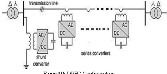
Figure10: DPFC Configuration
The DPFC has same capacity as UPFC to adjust the line parameters, i.e., line impedance, transmission point, and transport voltage size (Sudharshan Rao et al, 2012 ).
A. Eliminate DC Link and Power Exchange
Inside the DPFC, the transmission line is utilized as an association between the DC terminal of shunt converter and the AC terminal of arrangement converters, rather than direct association utilizing DC-connect for power trade between converters. The strategy for power trade in DPFC depends on power hypothesis of non-sinusoidal parts (Qing Fu et al,2012 ). In light of Fourier arrangement, a non-sinusoidal voltage or current can be exhibited as the whole of sinusoidal parts at various frequencies. The result of voltage and current segments gives the dynamic power. Since the essential of certain terms with various frequencies are zero, so the dynamic power condition is as pursue Where Vi and Ii are the voltage and current at the ith consonant, individually, and φi is the point
[image:7.612.168.461.84.215.2]B. Advantages of DPFC
1) High control capacity: The DPFC can control all parameters of transmission Network line impedance, transmission point and transport voltage extent.
2) High unwavering quality: The arrangement converters repetition builds the DPFC dependability amid converters task (Ma Zhengbo et al,2011 ). That is to say, on the off chance that one of arrangement converters fizzles, the others can keep on working.
3) Low cost: The single-stage converters rating, in correlation with three-stage converters is low. Moreover, the arrangement converters, in this design, no compelling reason to any voltage disengagement to interface in line. We can utilize the single turn transformers for arrangement converters hanging. To investigate the attainability of the DPFC, a contextual analysis which is to utilize DPFC to supplant UPFC of the Korea electric power company (KEPCO) is researched. To accomplish a similar control capacity as the UPFC, the DPFC development requires less material (Qing Fu et al,2012 ).
REFERENCES
[1] SudharshanTRaoTGandimeniTandTVijayTKumarTK.T(2012),UNIFIEDTPOWERTQUALITYTCONDITIONER(UPQC)TVSRDTInternationalTJournalTofT
Electrical,TElectronicsT&TComm.TEngg.TVol.T2T(8),T2012T.
[2] P.RamTKishoreTKumarTReddyTandTDr.TK.S.RT.Anjaneyulu, ATNEWTTECHNIQUETFORTIMPROVING POWERTQUALITYTINTPOWERTTRANSFORMER BYTFPGA JournalTofTTheoreticalTandTAppliedTInformationTTechnolo gyTpp.169-175
[3] MetinTKeslerTandTEnginTOzdemirT(AprilT2009),SIMPLIFIEDTCONTROLTMETHODTFORTPOWERTQUALITY
CONDITIONERT(UPQC)TInternationalTConference TonTRenewableTEnergiesTandTPowerTQualityT(ICREPQ’09)Valen ciaT(Spain),T15thTtoT 17th.
[4] AhmadTJamshidiT,S.TMasoudTBarakatiTandTM.TMoradiTGhahderijaniT(OctT2012),TIMPACTTOFTDISTRIBUTEDTPOWERTFLOWTCONTROLLER
TTOTIPROVETPOWERTQUALITYTBASEDTONTSYNCHRONOUS FRAME METHODTIACSITTInternationalTJournalTofTEngineeringTa ndTTechnology,TVol.T4,TNo.T5.
[5] AhmadTJamshidi,S.TMasoudTBarakatiTandTMohammad Moradi GhahderijaniT(2012)TPOWERTQUALITYTIMPROVEMENT
TANDTMITIGATIONTCaseT978-1-4673-0158-9/12/$31.00,IEEETpp464-468
[6] ArupTRatanTBhowmikTandTChampaTNandi.ImplementationTofTUNIFIEDTPOWERTFLOWTCONTROLLERT(UPFC)TFORTPOWERTQUALITYTIMP ROVEMENTTinTIEEET14-Bus SystemTInt.TJ.TComp.TTech.TAppl.,TVolT2T(6),1889-1896
[7] ParvejTkhanTandTHimmatTsinghT(DecT2012).POWERTFLOW CONTROLTINTATRANSMISSIONTLINET TTHROUGH UPFCTInternationalTJournalTofTEmergingTTechnologyT andTAdvancedTEngineeringT(ISSNT2250-2459,VolumeT2,TIssueT12)
[8] SandeshTJain,TProf.TShivendraTSinghT ThakurTandT
Prof.TS.P.TPhulambrikar(DecT2012).TImproveTPowerTQualityTAndTReduceTTheTHarmonicsTDistortionTOfTSensitiveTLoadTInternationalTJournalTo fTEngineeringTResearchTandTApplicationsT(IJERA) ISSN:T2248-9622TVol.T2,TIssueT6,Tpp.806-815
[9] QingTFu,TGuilongTMaTandTShuhuaTChen.TIMPROVETPOWERTQUALITYTWITHTHIGHTPOWERTUPQCTinTtheTproceedingTofTPowerTQualityT
HarmonicsTAnalysisTandTRealTMeasurementsTDataTwww.intechopen.comTpp153-170
[10] MaTZhengbo,TLiTLinchuanTandTDongTTuo. APPLICATION OFTATCOMBINEDTSYSTEMTTOTENHANCETPOWER QUALTYT INTANTISLANDTMICROGRIDTpublishedTinTconferenceT978-T1-4244-9690-7/11/$26.00T©2011IEEE
[11] RosliTOmar,TNasrudinTAbdTRahimTandTMarizanTSulaiman(2009),TMODELINGTNTANDTSIMULATIONTFORTVOLTAGETSAG/SWELLTMITIGA TIONTUSINGDYNAMIC VOLTAGETRESTORE (DVR)TJournalTofTTheoreticalTand AppliedTInformationTTechnology,TVol.5,TNo.T4,pp-464-470