Analysis and Comparison of Structure having
different Infill Material (Red Brick, AAC Block,
Hollow Concrete Block) using ETABS Software
Tushar Raju1, Dr. Rakesh Patel2
1
M.Tech Student, 2Prof. & H.O.D, Department of Civil Engineering SIRTS, Bhopal
Abstract: Reinforcement concrete structure frame system widely used around the world. In building structure, structure element is generally taken as Beam, column, foundation.
The dead & live load is transforming from beam to column, column to footing then ultimately load distributed into the soil. The wall load is taken by beam. In building design we mentioned the entire wall over the beam if it is possible, if it is not possible we taken concealed beam into the slab below the wall. During the analysis of frame structure we consider wall as non structural element. But presence of infill wall in the structure analysis is play important role. In the current study deals with the investigation of the effect of infill in building and their behaviour in structure.
In present situation high rise building constructed with the different types of infill wall. Some of them generally use for example Red brick, AAC wall, Hollow concrete block, light weight Aluminium & Steel panels. So, three types of modal create on ETABS software.
In this study 20 storey high rise building is modal in ETABS with taken three types of infill materials Red brick, AAC block, Hollow concrete block considered for analysis which is located in most critical earthquake zone v. Dynamic analysis is done using ETABS software, soil conditions are to be medium and importance factor is to be taken as 1.2. the all three infill wall modals compare with the basic design parameter like moment, shear force, displacement and as well as earthquake parameter like story drift, story shear, base shear, time period etc.
Keywords: ETABS, Structural Analysis, Soft storey, masonry infill, RC frame, earthquake, displacement, drift, base shear, AAC blocks, Hollow concrete block
I. INTRODUCTION
In present condition increasing in the population, housing has developed as a industry due to high rise building is only solution in the metro cities. But the performance of high rise building also important in all weathering condition and design vertical loading condition as well as lateral loading condition .due to frequent occurrence of the earthquake in the world. The demand of earthquake resisting building is increase.
The objective of the study is to analysis the building structure with different type of infill material wall in dynamic loading condition which is analysis by the Time history method.
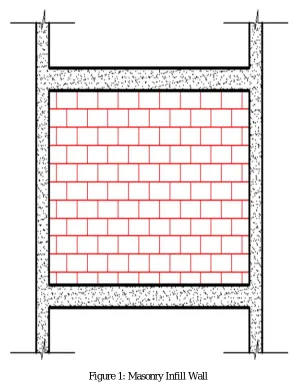
The infill wall is the supported wall that closes the inner or outer perimeter of a building constructed with reinforcement concrete work like beam & column.
Therefore, the structural frame deals to transform the load to one member to another member due to these is called frame bearing function, whereas the infill wall serves to separate inner and outer space. The infill wall has the unique static function to bear its own weight.
Figure 1: Masonry Infill Wall
Many researchers focuses in the behavior and impact of the infill wall in the structure during the vertical and lateral loading condition.
1) Md Irfanullah et. al. (2013): Masonry infill wall treated as non structure element in India . & their strength and stiffness contribution are neglected. But present of infill wall change behavior of the frame action into truss actions. In these paper three type of model as had been created , first is building without infill wall & with infill wall load , second is full infill masonry model with all story & below the plinth level , third is full infill masonry but expect below the plinth level. Provision of infill wall enhances the performance in the terms of story displacement & drift control and increases in lateral stiffness.
2) Omprakesh et. al. (2017): Paper focus on the investigation of the effect of infill in building & their behavior in structure using different type of infill walls. Four types of model has been modeled in the ETABS software , first is RCC frame taking infill masonry weight neglecting effect of stiffness , second is effect of stiffness is considered , third is weight of infill excluding soft ground story , fourth is weight of infill including soft ground story . Modeling has been done by equivalent brace frame as equivalent diagonal strut provided as in place of infill wall. All model perform under the static analysis, AAC block and hollow concrete block give appropriate results compare to other infill walls.
The main objective of this study is to determine the following:
a) To Determine the Analysis of a Building structure with various types of infill walls
b) To determine performance of building structure with infill walls in zones v.
c) To analyse the implementation of SRSS Method in tall structure using ETABS.
[image:3.612.75.538.154.659.2]d) To compare normal conventional building with building with different infill wall building with behaviour in loading and other structure parameter.
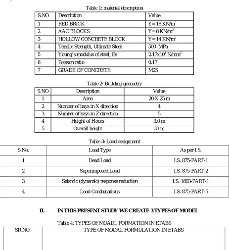
Table 1: material description
S.NO Description Value
1 RED BRICK Y= 18 KN/m3
2 AAC BLOCKS Y= 8 KN/m3
3 HOLLOW CONCRETE BLOCK Y= 14 KN/m3
4 Tensile Strength, Ultimate Steel 500 MPa
5 Young’s modulus of steel, Es 2.17x10⁴ N/mm2
6 Poisson ratio 0.17
7 GRADE OF CONCRETE M25
Table 2: Building geometry
S.NO Description Value
1 Area 20 X 25 m
2 Number of bays in X direction 4
3 Number of bays in Z direction 5
4 Height of Floors 3.0 m
5 Overall height 33 m
Table 3: Load assignment
S.No. Load Type As per I.S.
1 Dead Load I.S. 875-PART-1
2 Superimposed Load I.S. 875-PART-2
3 Seismic (dynamic) response reduction I.S. 1893-PART-1
4 Load Combinations I.S. 875-PART-5
II. IN THIS PRESENT STUDY WE CREATE 3 TYPES OF MODEL
Table 4: TYPES OF MOADL FORMATION IN ETABS
SR NO. TYPE OF MODAL FORMULATION IN ETABS
1. RCC FRAME TAKING WITH INFILL WALL LOADING. (CALCULATED VALUE)
2. RCC FRAME WITH ASSIGN INFILL WALL PROPERTIES IN ETABS.
III. LOADING CALCULATION
A. Dead Load 1) Wall Load
a) FLY ASH Brick = 0.2X 18X (3-0.5) = 9 KN / m2
b) AAC Block = 0.2 X 8 X (3-0.5) = 4 KN / m2
c) Hollow Concrete = 0.2 X 14 X (3-0.5) = 7 KN / m2
2) Slab Load
a) 0.125 X 25 X 1 +1 = 4.2 KN / m2 (Including floor finish)
3) Live Load: ASSESSABLE AREA – 2 KN / m2
Live Load (Seismic calculation) 25% of Live load :- 0.5 kN/m2
4) Sesmic Load: All frames are analyzed for (V) earthquake zone. The seismic load calculation are as per IS: 1893 (part-1)-2016.Seismic force parameters for proposed issue.
B. Diagonal Strut Member
For the presence of infill in our building frame modal, we can create a diagonal (strut) member in frame structure , The width of
strut depends on the length of contact between the wall & the columns (αh) and between the wall & the beams (αL). The
formulations for αh and αL on the basis of beam on an elastic foundation has been used given by Stafford Smith (1966). Hendry
(1998) proposed the following equation to determine the equivalent or effective strut width w, where the strut is assumed to be subjected to uniform compressive stress.
Where, Em is elastic modulus of masonry wall, Ef is elastic modulus of frame material, t is thickness of infill, h is height of infill and L is length of infill, Ic is moment of inertia of the column, Ib is moment of inertia of the beam and θ = tan-1 (h/L).
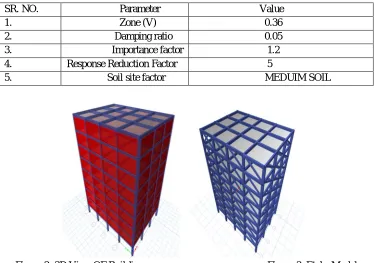
SR. NO. Parameter Value 1. Zone (V) 0.36 2. Damping ratio 0.05 3. Importance factor 1.2 4. Response Reduction Factor 5
[image:4.612.239.386.331.408.2]5. Soil site factor MEDUIM SOIL
Figure 2: 3D View OF Building Figure 3: Etabs Modal
[image:4.612.120.494.451.714.2]IV. FLOW CHART OF THE STUDY
A. Analysis Results
For this research work following outcomes are observed:
1) It is observed in above results that bending moment is comparatively more in bare frame, thus green sustainable frame case results in stable structure with less reinforcement requirement.
2) As bending moment is higher in bare frame results thus heavy section is required which will result in less unbalance (shear) force.
3) In the above chapter results shows that green sustainable structure is comparatively economical than bare frame by 8.4%.
V. SUMMARY
A. From the results, it has been found that displacement of structure with AAC block in all three modal cases is found less than conventional brick masonry.
B. While comparing the modals 1,2,3 for displacements in all the three models model 3 (infill frame) is having least displacement. In model 3 we have considered the strength and stiffness of material is replaced by a equivalent diagonal strut hence it has got least deflections.
C. It is observed from the results that storey shear with AAC and hollow concrete masonry is significantly less when compared to brick masonry infill panel. It is due to the light weight of AAC blocks and hollow concrete.
D. Model M-2 has more storey shear than M-1, and M-3 because Storey shear depend on stiffness of the frame. The struts in masonry infill resist the lateral seismic forces through axial compression along the strut. The contribution of infill increases the stiffness of the frame this resulting increase in seismic forces. Model M-1 has the least value of storey shear with all three types of infill materials because stiffness has not been considered in case M-1.
REFERENCES
[1] http://en.wikipedia.org/wiki/Sustainability Mehta, P.K., Global concrete industry sustainability, The Indian Concrete Journal, February 2009, Vol. 83, No.2, pp. 45-48.
[2] Swamy, R.N., Sustainable concrete for the 21st century-concept of strength through durability, The Indian Concrete Journal, December 2007, Vol. 81, No.12, pp.7-15.
[3] Kalgal, M.R., Sustainable development with concrete, ICI Journal, Vol. 9 No.4 October-December 2008, pp.11-16. [4] Desai, S., Safe, high-tech and sustainable concrete construction, Construction Materials, May 2008, 6, Issue CM2, pp. 85-90. [5] Subramanian, N., Sustainability - Challenges and solutions, The Indian Concrete Journal, December 2007, Vol. 81, No.12, pp.39-50.
[6] Tande, S.N. and Krishnaswamy, K.T., Greening of Concrete Industry for environmentally compatible and sustainable structures, The Indian Concrete Journal, May 2009, Vol. 83, No.5 pp.39-44.
[7] Commision of European Communities (1991), Solar Architecture in Europa, Brussels, BelgiumÇelebi,
[8] G., Gültekin, A. B. , UlukavakHarputlugil, G., Bedir, M., Tereci, A., (2008), Yapı - Çevreİlişkileri, TMMOB MimarlarOdası, SürekliMeslekiGelişimMerkeziYayınları - 10, İstanbul Ionescu,
[9] C., Baracu, T., Vlad, G. E., Necula, H., &Badea, A. (2015). The historical evolution of the energy efficient buildings. Renewable and Sustainable Energy Reviews, 49, 243-253.
[10] O’Connor, J.M., (2015), Architecture&Passive Design, Design Media Publishing, Hong
[11] Kong Schuetze, T. (2015), Zero Emission Buildings in Korea—History, Status Quo, and Future Prospects, Sustainability, 7, 2745-2767; doi:10.3390/su7032745