©IJRASET: All Rights are Reserved
805
SMD based LED Design
Arth B Patel
Electrical Engineering Department, Ganpat University
Abstract: This claim is to be provides an introduction to the basic principles of heat transfer and its collision on LED applications using thermal management at diverse system levels. It describes and discusses relevant characteristics.
Keywords: Heat indulgence conduit, Material property, SMD Type LED, Impact of thermal resistance.
I. INTRODUCTION
Light-emitting diodes (LEDs) are used and accepted in many areas of lighting technology at the present time. They are light sources of the future, and already signify the latest state of technology for lots of applications. Thanks to the direct transfer of electrical current to light (optical radiation) in the semiconductor, LEDs are highly proficient – more efficient than most traditional light sources [1, 4].However, even in the case of LEDs, nearly most of the electrical power is converted to heat rather than light. To put it simply, the higher the current, the more heat is created in the component. This heat loss must be conducted away from the LEDs, since the used semiconductor material is subject to a greatest temperature limit and because its attribute properties such as forward voltage, wave length, and service life may vary with the temperature. In particular in the case of innovative, miniaturized high-performance LEDs, the dissipation of heat is centrally important in order to keep temperatures down – and is regarded as the biggest challenge. Only adequate thermal management across all system levels can allow the full mistreatment of LED performance and efficiency for the duration of operation. This paper provides a general introduction to the basic principles of heat transfer and its manipulate on LED applications Using thermal management at different system levels. significant characteristics are described and discussed in this framework.
II. BASICPRINCIPLESOFHEATTRANSFER
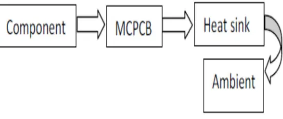
[image:1.612.169.445.492.608.2]In the case of LED systems and other forms of electronics with a certain amount of heat Loss (70%), the aim is generally to transfer this heat into the ambient air to a lesser or greater extent in order to prevent the overheating of components[1].The system heat transfer path is the same in practically all cases, starting from the heat source (semiconductor junction layer) via the PCB, heat sink, and into the ambient air. Here, the term "heat" designates a form of energy which can be transmitted through various mechanisms from one medium to another in the form of a heat flow.
Fig. 1 General Heat removal path of the system
Transmission always takes place at points where there are temperature differences within one medium or between media with different temperatures. The energy is always transmitted from the medium with the higher temperature to the medium with the lower temperature (direction of heat flow – 2nd laws of thermodynamics)[4]. The following three basic heat transfer mechanisms are described in more detail below:
1) Conduction
2) Convection
©IJRASET: All Rights are Reserved
806
A. Thermal Conduction
Thermal conduction is a mechanism for the transport of thermal energy that does not require a macroscopic flow of material. The exchange/transport of heat takes place between neighbouring particles and can be depicted more or less as the transfer of vibration [1, 4].For example, in the case of metals the heat is transmitted between the atomic kernels via vibration energy; energy is also transported through the collision of the freely moving charge carriers.The heat transmitted through thermal conduction is described by Fourier's Law.
Q = λ*A (T1-T2) /L Where,
Q =Total Heat
λ =Material Property
A =surface area
(T1- T2)= Temperature difference between 2 parts L= Length of object
Thermal conductivity describes the ability of a solid, liquid, or gas to transport thermal energy. The typical thermal conductivity values of materials used in an LED system are shown in Table-1.
TABLE-1
Thermal Conductivity Of Material Used In Led System
Material Thermal conductivity
Air 0.026
Aluminium 200
Aluminium Alloy 120-180
Copper 385
FR4 0.3
MCPCB 0.2
The thermal conductivity of metals is typically between 10 and 400 Wm-1K-1. Metal alloys conduct heat less well than their components. As a rule, semiconductors also have a high thermal conductivity. If you apply a voltage to different surfaces of a solid, you create a flow of electrical current. Similarly, if you apply different temperatures to the same surfaces, you create a flow of heat. Like electrical resistance, a thermal resistance of Rth can be defined for one-dimensional thermal conductivity. This thermal resistance is subject to the premise of one-dimensional heat transfer. This occurs when the heat conductor is adjacent to a medium with poor thermal conductivity. More complex structures with three-dimensional heat flows where all heat transfer mechanisms are taken into account can usually normally only be calculated using numerical simulations.
B. Impact of Thermal Resistance
Thermal resistance [K/W] is used to assess thermal conductivity. At a given rate of loss (heat flow), it gives the temperature difference between the start and end of the heat path. It is derived from adding together the thermal resistances of the path sections through which the heat flow must pass [5].
C. Heat Convection
©IJRASET: All Rights are Reserved
807
D. Thermal Radiation
Unlike conductivity and convection, heat transfer through radiation takes place without a carrier medium through the absorption and emission of electromagnetic waves. Everybody above a temperature of T = 0 K emits electromagnetic radiation in the visible to
infrared range (0.35 - 10 μm)[3,4]. The thermal energy transmitted through radiation depends on the physical properties of the
surface material and the geometrical arrangement of the transmitting and receiving surface (view factor). The emissivity e is the
characteristic parameter for the absorption and emission of thermal radiation of a surface.
Q = α*A (T1-T2) Where,
Q =heat transferred, J/s = W
α = heat transfer coefficient, W/(m2 K)
A= transfer surface, m2 T1 = Plate temperature, K T2 = Air temperature, K
In practice, the heat transfer coefficient is determined experimentally with the help of model tests. The test results can then be applied to other convective heat transfer conditions. A black body (ideal heat emitter) would fully emit and absorb all electromagnetic radiation incident upon it with every wavelength (e = 1). In contrast, the surface of a real body only emits part of this radiation. Thus, real objects are called "gray" bodies (e < 1). The emissivity of a body thus describes the amount of radiation that it emits in comparison with a black body.
TABLE-2
Important Emissivities For Led Application
Surface T in C0 ε
Aluminium -Polished
-Heavily oxidized
20 20
0.04 0.25
Lacquers 100 0.9-0.97
Plastic 20 0.9
Solder stop mask 20 0.9
The material of a body and its surface character has a significant influence on emissivity. As a rule, non-metallic and non transparent objects are good heat emitters, with an emissivity of > 80%. The emissivity of metals can vary between 5% and 90%. The shinier a metal, the lower its emissivity. For examples of the emissivity of typical materials used in an electronic system, see Table-2.There is a standard thermal radiation equation for the special case of the emission of radiation into half-space (Stefan-Boltzmann Law). It summarizes physical and geometric influencing factors to describe the heat flow exchanged through thermal radiation.
Q = ε*A*σ (T14-T24)
Where,
Q=heat transfer
A=area of heat transfer
T=temperature difference
ε=Emissivity coefficient (0 < ε <1)
σ= Stefan-Boltzmann constant
In electronics cooling, cooling via thermal radiation has a significant importance for passively cooled systems (free convection). The contribution made by thermal radiation to cooling can be up to 50%. In the case of active cooling, the dissipation of heat through
thermal radiation has a lesser role in comparison to heat dissipation through convection. At PCB level, solder resist (ɛ~0.9) is
©IJRASET: All Rights are Reserved
808
III.THERMALMANAGEMENTOFLIGHTSOURCESBASEDONSMDLEDSFor the realization of LED light sources, thermal management remains a major task and challenge. Despite its high efficiency, even in the case of LED technology nearly most of the electrical power is converted into heat In addition, the continuing miniaturization of housing technology results in an increase in power and packing density, which means that the heat is incident upon and must be dissipated from an ever decreasing amount of space [3].The aim of thermal management – the transfer of heat from the chip to the ambient environment – is always the same. The challenge lies in the adequate design/implementation for the specific power class and constraints of the relevant application area. As a rule, the thermal management of an LED system can be broken down into three system levels:
A. LEDs
B. Sub mount
C. Cooling Unit
The heat path for system heat transfer can be described in the same terms.
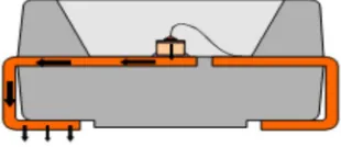
Fig.2 Heat transfer in LED system
The heat generated in the LED barrier layer is transmitted through the LED housing (package) via the soldered joint and on to the carrier (PCB).At PCB level, the heat can be transported to the heat sink by various design measures (horizontal and vertical thermal conductivity. From the cooling unit (e.g. heat sink, system housing), the heat is finally transferred to the ambient environment through heat convection and thermal radiation. Thermal resistances shown in Fig. are often used for visualization purposes, particularly in the case of complex systems [4].
Fig.3 Visualization of an LED system via a thermal resistance network
The thermal partial resistances correspond to the various functional groups in the system or heat path and characterize their individual thermal behaviour. Rth JS is the thermal resistance of the LED and describes the transfer of heat within the LED housing
(junction-to-solder-point); Rth SB is the thermal resistance of the PCB technology (solder-point-to-board);Rth BA is the thermal
©IJRASET: All Rights are Reserved
809
IV.THERMALMANAGEMENTATLEDLEVELAt LED level, thermal management is generally predefined by the component manufacturer and is determined by the design of the LED. The thermal resistance of an LED tells us about its thermal properties. This thermal resistance is usually stated on the LED data sheet as a characteristic parameter. As a general rule, the smaller the thermal resistance of an LED, the faster the heat can be dissipated from the housing. Significant influencing factors on thermal resistance include the technology used for the housing and the light-emitting semiconductor chip. In general, the SMD LEDs available at Opto Semiconductors can be divided into two groups:
1) Lead-frame-based LED housings
2) Ceramic-based LED housings
Although the thermal properties of an LED are fixed, knowledge of the heat path of the LED is decisive for the thermal design of the PCB and system.
A. Heat Path of Lead Frame Based LEDs
[image:5.612.229.384.291.358.2]In the case of a lead-frame-based housing, the semiconductor chip is mounted on a lead frame which – in most cases – consists of a plated copper alloy[2,3].The connection can be glued or soldered Starting from the barrier layer, the heat is primarily dissipated from the package via the chip and lead frame Fig. The amount of heat transfer that takes place via the bond wire is insignificant.
Fig .4 Heat conduction via lead(s)
In another variant of this group, an additional internal heat spreader is embedded in the housing. The LED chip is mounted directly onto this. This means that even internally the heat is already distributed over a larger area and can be better dissipated due to the larger cross section. This type of design is used in Golden Dragon LEDs from Opto Semiconductors, for example Fig.
Fig. 5 Heat spreading and conduction via heat spreader/lead
B. Heat Path of Ceramic-Based LEDs
[image:5.612.222.385.643.712.2]In the case of LED packages based on ceramic substrates, the semiconductor chip is attached to the metallization layer of the ceramic. Aluminium oxide and aluminium nitride are established materials here [2]. The good thermal conductivity (Al2O3: ~20 Wm-1K-1, AlN: 170 Wm-1K-1) of the ceramics enables heat spreading in conjunction with the metallization layer. The heat that arises in the semiconductor is distributed via the metallization layer and ceramic base material and transmitted to the PCB via the solder pad. Certain LED designs have an additional "thermal pad" in addition to the two electrical contacts. This has purely thermal function for primary heat dissipation and is electrically neutral. As a rule, the thermal pad is positioned centrally directly below the semiconductor chip Fig. as below
©IJRASET: All Rights are Reserved
810
V. THERMALRESISTANCERTH,JSOFANLEDWith classical silicon-based semiconductor components such as integrated circuits and transistors, all of the dissipation power is converted into heat. The heat flow is thus equivalent to the electrical power loss, which results in the clear interpretation of the thermal resistance [5]. In the case of light-emitting diodes (LEDs), however, only a part of the supplied electrical energy is converted into heat. Some of the electrical energy is emitted as light/radiation (optical energy) in accordance with optical efficiency. This leads to two different definitions of thermal resistance for LEDs:
A. Electrical Thermal Resistance
Thermal resistance is defined in the same manner as for traditional semiconductor components [3, 5].The decoupled energy (light/radiation) is not taken into consideration (see JEDEC 51-1).
Pheat = Pel Pel = Uf.If Rth, electra = ∆T/Pel
B. Real Thermal Resistance
This definition of thermal resistance considers the actual flow of heat that is dissipated through the housing. The decoupled optical power of the LED is thus taken into account (see JEDEC 51-50).
Pheat = Pel - Pout Rth,real = ∆T/Pel - Pout Rth,real = ∆T/Pel (1- ᶯLED )
Where,
ηLED = optical efficiency of the LED
This value is independent of the working point of the LED and can therefore be used to characterize the LED housing [5].The use of real thermal resistance when considering thermal layout can ensure that the maximum permissible junction temperature is not exceeded in all possible modes of operation.
VI.CONCLUSSION
We analyze in SMD type LED the thermal behaviour of the LED component is firm by the maker via the internal design. The static
thermal properties are described by the thermal resistance Rth JS, real. For thermal management, the flow of heat through the housing
is of significant importance. These heat paths must be taken into account for the thermal design of the PCB. So that improves thermal management at the PCB level.
REFERENCES
[1] Ramazan Ayaz Ali Durusu Hakan Akcal, Yusuf Yasa. Thermal management of high power led. 3rd International Conference on Renewable Energy Research
and Applications, IEEE Oct. 2014.
[2] SEOUL Semiconductor design of Z-power LED.
[3] Effect of Thermal management of Crystal is SMD LEDs. July, 2015.
[4] Chun-Jen Weng, “Advanced thermal enhancement and management of LED packages”, International Communications in Heat and Mass Transfer, Volume
36, Issue 3, March 2009, pp 245–248.
[5] S.-L. Kuo, C.-K. Liu, M.-J. Dai, C.-K. Yu,H.-C. Chien and C.-Y. Hsu,“Characteristics of Thermal Resistance for High Power LEDs,” in 200810th Electronics