MCU-Based Aquaculture System
V. B. De Leon, A. H. Ballado Jr., P. Dychitan Jr., R. Gustilo
Abstract—Developments in the field of control technology stretched the limits of its application in the field of aquaculture. Hence, this study was carried out to utilize microcontrollers to provide the necessary control of several variables or parameters i.e., pH, temperature and water level in an aquaculture system. The versatility of microcontroller programming allowed the manipulation of the range of parameter values, which could be altered depending on the needs of the system. Likewise, other features of the study included ease of monitoring and data logging. The construction of a simulation tank exhibiting different water quality conditions was carried out to capture dynamic aquacultural situations. Remote monitoring and data collection were an integral part of this study. However, the researcher welcomes further improvements in terms of additional parameters - oxygen level, salinity, phosphate level, and the like - necessary for optimum fish growth, and the use of modern advanced control algorithms to improve the system’s efficiency and speed.
Index Terms - microcontroller, aquaculture system, remote terminal unit, data logger
I. INTRODUCTION
It is relatively fitting that tilapia can be called colloquially as “aquatic chicken” because of its high growth rate, adaptability to a wide range of environmental conditions, growth and reproduction even in captivity. Not quite surprisingly, this fish has become an excellent candidate for aquaculture, especially in tropical and subtropical environments. Raising tilapia as an inexpensive meat source can be very promising considering the health risks and high costs associated with the consumption of red meat.
Tilapia culture is believed to have originated more than 4000 years ago, but very little information was available on their culture during those ancient times. Tilapia farming began from the Nile Valley and spread to central and western Africa.
Manuscript reviewed February 28, 2011; revised June 29, 2011. This work was supported by the ERDT program of the Department of Science and Technology.
V. B. de Leon finished his MS ECE in Mapúa Institute of Technology. He also holds a MS Math degree from Ateneo de Manila University. He finished his BS ECE from Rizal Technological University. He is currently pursuing his PhD in ECE in Mapúa Institute of Technology. (email: [email protected]).
A. H. Ballado Jr. received his BS ECE in 1995 from Mapúa Institute of Technology Manila, Philippines. He earned his MS in Electronics Engineering also from the same Institute, in 1999. Currently, he is a candidate for a PhD in Electronics Engineering at the De La Salle University, Philippines. Presently, he is a professor and the program chair of the Electronics Engineering program in Mapúa. (e-mail: [email protected]).
P. M. Dychitan Jr. finished his BS ECE in Don Bosco Technical College in 1993. He is at present the president of Dychitan Electronics Corporation. (e-mail: [email protected]).
The first trials of tilapia aquaculture were recorded in Kenya in the 1920s, while artificial introductions of this species in many Asian and some Pacific Island countries started in the 1950s [1]. Since then, breeding of tilapia has been established in many tropical and subtropical regions, and even in areas beyond their native ranges, where they have been introduced for various purposes. As a result, considerable attention has been paid to tilapia aquaculture during the past three decades. Tilapia farming is expanding worldwide in both developed and developing countries because this group of fish can be cultured under very basic conditions. While it is ideal for rural subsistence farming, tilapia is amenable to more sophisticated, market-oriented culture programs, for these fish have high reproductive and growth rates, are relatively disease-free and hardy in nature [2]. Tilapia aquaculture is currently practiced in more than a hundred countries all around the globe yet alongside the popularity of culturing tilapia are important growth factors that need to be considered which include pH, temperature, and water level (depth); hence, the monitoring and control of these parameters through the utilization of control systems will be the goal of this research.
Through the use and application of control systems, this study will monitor and control each factor based on set values of parameters affecting the growth of the fish. The resulting controlled environment after the application or implementation of process control mechanisms will be crucial in determining the success of growing excellent quality tilapia fit for high-demand human consumption. Generally, the objective of this research is to construct/ build a control system for aquaculture. Specifically, this research seeks to:
create an algorithm incorporating the monitoring and control of pH, temperature and water level of the aquatic environment;
design a control system for monitoring and control of the three growth factors: pH, temperature, and water level;
provide means/ solutions for maintaining the ph, temperature, and depth of the water environment based on specified set values; and
utilize C language for the source code or program to implement the algorithm.
II. METHODOLOGY
The procedures in designing and building the control system in automating tilapia aquaculture will be discussed systematically in this section. The block diagram of the proposed system is shown in Fig. 1.
Sensors being used as transducers will send appropriate signals to the microcontroller which will adjust the factor/s that need/s to be corrected. Altogether, these devices will give the control necessary to maintain set values of parameters for tilapia aquaculture.
Microcontroller Programmed in C language Water Tank Environment
Temperature Sensor
Water Level Sensor
pH Sensor Pump
Water-composition
Correcting Facility
Inlet Valve
Drain Valve
Pump
Electrical
Relays Data logger
Wi-Fi Router
[image:2.595.42.279.331.614.2]Laptop Computer
Fig. 1. Block diagram for the control system implementation for tilapia aquaculture.
Start
Measure pH, Temp and Water Level
Passive mode?
High pH? High pH correction
High pH correction steps
done?
Low pH? Low pH correction
High Temp?
Passive mode
Low Water level?
Close tap water valve Yes
Yes
Yes
Yes
Yes
B
B
High temp correction B
Open tap water valve No
No
No
No
No
B A
A
A
A
Passive mode Low pH correction steps
done?
Passive mode High Temp correction steps
done? Yes
Yes
Yes No No No
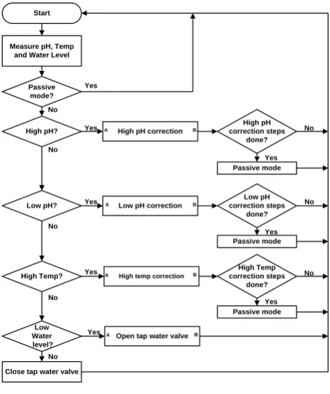
Fig.2. Process algorithm.
The simulation tank holding 15 gallons of water will be equipped with temperature, pH, and water level sensors strategically placed inside the tank. It is provided with a drain valve that would flush out water in the event of water-quality correction. An aerator (with a built-in filter) installed in the system will distribute oxygen evenly in the water.
The tank comes with two reservoirs, one containing alkaline water and tap water on the other, which will neutralize acidity or alkalinity beyond the specified range of values ideal for tilapia growth. Likewise, a reservoir for cold water for water temperature correction is also supplied. Pumps are attached within the tanks to hasten the flow of water/ solution from the reservoirs. Similarly, a pump was attached to the drain valve to ensure faster water exit.
Data will be gathered every 15 minutes and can be monitored indefinitely. For this study, six hours of monitoring were observed for a given date. If water-correcting action is being done, this will be included within the data log. A visual display showing the status of parameters and sensor actions for periodical inspection was also supplied. Range of values of parameters can be interactively altered with this display using the microcomputer. The microcontroller comes with a data logger where one can monitor the status of the system. The following are the considerations and parameters involved in the operation of the MCU-based aquaculture system:
At the heart of the system is an RCM 4300 RabbitCoreMicroController Unit which will be used to provide control. It comes with a data logger and equipped with relays.
The pH sensor (8205 Digital pH Transmitter/ Burkert, Germany) will measure the acidity of aquarium water. Depending on the detected water chemistry, it will send the appropriate signal to the microcontroller which will in turn perform the necessary control action with the opening or closing of water-composition-correcting valves through relays.
The temperature sensor (8400 Screw-in Temperature Sensor, Burkert, Germany) will measure the temperature of aquarium water. If water is too warm based on a given set of values, it will send a signal to the microcontroller which will in turn trigger the opening of the cold-water reservoir valve (mineral water dispenser).
Two float level switches/ sensors (top level/ bottom level sensors) will detect the depth of water in the tank. Both switches are closed when submerged in water and opens when water level is below the switch.
Indicators (LEDs) in the relay board will indicate which valve is open or close to indicate correcting action.
Alkaline reservoir which contains limewater solution (hydrated calcium oxide) will provide the base to neutralize acidity (neutralization reaction).
Tap water reservoir will supply water into the tank as correcting action if aquarium water gets too basic or if water level dips below the level sensors.
Cold-water reservoir will provide the water for cooling action if aquarium water gets too warm.
Solenoid valves (6013 Compact Solenoid Valve, Burkert, Germany) 1/8 ” diameter will open/ close appropriately in the process of water chemistry correction and are connected to the drain, tap and alkaline solution reservoir.
Water is circulated around the system with a submersible pump.
The simulation tank is a 15-gallon translucent aquarium for easy observation.
For the initial conditions in the design of the aquaculture system, the parameters ideal for tilapia growth were used. These were the following:
a) pH range of 6.5 – 8.0 [3] b) temperature of 30 °C or less [4]
c) water level just above the top level sensor [5]
From tilapia culture literature, it was noted that the fish will attain optimal growth if water quality is maintained with a pH of 6.5 to 8.0. Values that would exceed the range above or below and maintained for several days would be fatal to the fish. Likewise, temperature exceeding 30 °C for prolonged periods will eventually result to fish kill. But temperatures below it, even lower than 25 degrees will have little effect on the fish.
It could be noted from the algorithm that pH control takes precedence over temperature control while water level is always maintained for every corrective action. Since the setup is indoors, temperature is a secondary consideration for control unlike pH level which could abruptly change the chemistry of the water resulting from the decay of feeds given to the fish and wastes coming from them in the form of dissolved salts [6]. Temperature change could be a slower process compared to pH change. Hence, if all parameters need to be corrected, it would be pH that would be given priority as evidenced from the main program.
The following status entries were used in the system to describe certain conditions:
High pH correction- a state where the pH of aquarium water is greater than 8.0
Low pH correction- a state where the pH of aquarium water is below 6.5
High Temperature correction- a state where the temperature of aquarium water is more than 30 °C Passive - a state where corrections had already been introduced followed by a time of inactivity Monitoring- a state where the system is “waiting” for water-quality deviations to occur
A. High pH Correction Algorithm
The system is pre-programmed to control the pH level from 6.5 to 8.0. When the pH of aquarium water regardless of its temperature exceeds a pH of 8.0 as sensed by the pH transmitter, the microcontroller will send a signal to the relay switch which will open the drain valve. Water will escape
from the aquarium for a period of 60 seconds (preset time delay). During this time, the top-level sensor would be open since water would have escaped already. No corrective action will take place if this time delay has not yet elapsed. Once this time elapsed, the drain valve will close and the corrective action will take place. Since the water quality is basic/ alkaline, it will open the tap water valve which would allow tap water from the tap water reservoir to flow to the aquarium. This process would continue until the top-level sensor closes. Once closed, the passive state will set in. This is the stage where no action takes place to give time for the system to adjust the correction done (settling time). Once the passive delay has elapsed (system has been preset with a passive delay of 60 seconds), the pH of the water will be measured again. If it falls within the range, then temperature will now be monitored with the water level maintained. Otherwise, the pH will be corrected again and the process above will be repeated. Refer to Figure 3.
A
Open drain valve
Water level below top sensor?
Wait for preset delay time
Time delay elapsed
Close drain valve and open tap water valve
Water level above top sensor?
Close tap water valve Correction Step : Done
B Yes
Yes
Yes No
No
No
Fig. 3. High pH correction.
B. Low pH Correction Algorithm
is the stage where no action takes place to give time for the system to adjust the correction done (settling time). Once the passive delay has elapsed (system has been preset with a passive delay of 60 seconds), the pH of the water will be measured again. If it falls within the range, then temperature will now be monitored with the water level maintained. Otherwise, the pH will be corrected again and the process above will be repeated.
C. High Temperature Correction Algorithm
When the temperature of aquarium water reaches more than 30 °C as sensed by the temperature transmitter, the microcontroller will send a signal to the relay switch which will open the drain valve. Water will escape from the aquarium for a period of 60 seconds (preset time delay). During this time, the top-level sensor would open since water would have escaped already. No corrective action will take place if this time delay has not yet elapsed. Once this time elapses, the drain valve will close and the corrective action will take place. Since the water quality is warm, it will open the water valve which would allow cold water from the cold-water reservoir to flow to the aquarium. This process would continue until the top-level sensor closes. Once closed, the passive state will set in. This is the stage where no action takes place to give time for the system to adjust the correction done (settling time). Once the passive delay has elapsed (system has been preset with a passive delay of 60 seconds), the temperature of the water will be measured again. If it still falls above 30°C, then the temperature will be corrected again and the process above will be repeated.
D. Automated pH Correction System Display
[image:4.595.310.502.330.495.2]The aquaculture system is provided with a display operating in real-time to provide an update of what is happening to the system as exhibited in Fig. 4.
Fig. 4. Sample screen display.
The Status field will tell us the condition of the system whether it is in high pH correction, low pH correction, high temperature correction, passive status, or monitoring status. The pH Level field will indicate the alkalinity or acidity of the aquarium water. The Temperature field will show us the present temperature of aquarium water.
The Top Level Sensor field will tell us if water level in the aquarium is above or below it.
The Drain Valve field will indicate if the drain valve is close or open. An open drain valve lets water out of the aquarium.
The Lime Water field will show us if alkaline water valve is open or close. An open limewater lets alkaline water out of the alkaline water reservoir to neutralize acidity.
The Tap Water field will tell us if the tap water valve is open or close. An open tap water means that tap water is introduced into the system to correct high pH or low water level.
The Cold Tap Water field indicates if the cold-water valve is open or close. An open cold tap water introduces cold water into the system to correct high water temperature. The Date/ Time field shows the present time and date.
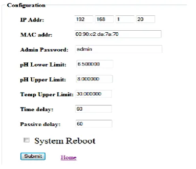
E. Configuration Display
An aquaculturist can alter the pH range and temperature setting of the system as depicted in Fig. 5. Likewise, the time delay and passive delay could be changed. The time delay for the system is defined as the time taken for the drain valve to release water from the aquarium.
Fig.5. Configuration display screen.
Passive delay for the system is defined as the time it takes for the system to remain in a state where no corrective action takes place. This is also the time aquarium water settles down after being corrected.
The pH Lower Limit and pH Upper Limit field could be changed to accommodate a range of pH values appropriate for the type of fish in to be cultured.
The Temp Upper Limit can be altered to allow a new temperature set point to be maintained.
The Time and Passive delay could likewise be reset.
III. RESULTS
Simulating different water conditions were done through
the use of concentrated alkaline solution, muriatic acid (hydrochloric acid), and water heater. For this simulation lasting six hours, the results were noted using the output of the data logger.
Fig.6. pH vs. time chart
The entries in the data log are in the following order: date, time of monitoring, status, pH level, temperature, top-level sensor status, and bottom- level sensor status.
A. Simulation and Data Logging
Data logging started on the first of December, 2010 at 3: 17 pm (System, Start up) and ended at 9:15 pm. For presentation purposes, time was expressed in minutes and pH values were the same numerical figures recorded in the data logger. The range of pH values maintained by the control system is from 6.5 to 8.0.
As presented in the data log, there were three instances when the graph was above the eighth pH mark (High pH Correction). The system responded to correct the high pH during the first simulated pH change. The pH was already correct at 7.96 recorded at 3:50 pm. We could conclude that it took around 27 minutes for this correction to take place. The second “shock” happened at 4: 42 pm. The pH of aquarium water was already correct at 4: 58 after more than 16 minutes. The last correction took place at 5:32 pm. The system corrected the pH after more than 15 minutes. The system stabilized at 5:52 pm.
The temperature to be maintained by the control system is 30 °C or less.
There were three instances where the graph was above the 30 °C mark indicative of a high temperature status of aquarium water. The system responded to correct the high temperature during the first simulated temperature change. The temperature was already correct at 29.6 °C recorded at 3:57 pm. We could conclude that it took around 15 minutes for this correction to take place. The second “shock” happened at 4:33 pm. The temperature of aquarium water was already correct at 4:42 after 9 minutes. The last recorded high temperature situation took place at 5:02 pm. The temperature stabilized at 5:09 pm. When water level goes above a sensor (top or bottom), the status of the sensor would read “above”. The opposite is true when water level is below the sensor, thus, the status of the sensor would read “below”. As monitored from 3:17 pm until 9:15 pm, the status of the two sensors was “below”. This will not come as a surprise, since water level is always maintained for every change in pH or temperature that will happen. One may also refer to the flowchart (see fig. 3) and note that water level is always checked or monitored every step of the way.
B. SMS Monitoring
Data logging apart from being directly done with a laptop computer via Wi-Fi can also be accomplished remotely through Short Message Service. The procedure would be carried by typing “1234 status” on a mobile phone and sending this message to 09279221966. Then, an SMS text message will be received by the sender displaying the status, date, time, pH level, temperature, water level condition (above or below), drain valve condition (open or close), alkaline valve condition (open or close), tap water valve condition (open or close) and cold water valve condition (open or close).
IV. CONCLUSION
An MCU-based aquaculture system proved that monitoring and control of different parameters or factors for optimum fish growth can be done easily and remotely. Unlike the earlier means of monitoring and control that involved actual visit to the site, these things could now be done conveniently through a mobile phone, or a laptop computer connected to the Internet.
Based on the results of controlling several variables altogether, we could conclude that one factor is related to another when simulations were done in the system, that is, temperature, pH, and water volume are all functions of each other. Consequently, a change in a variable will favor a corresponding change in the other. Also, the monitoring of pH based on the sampled monitoring period showed that pH correction is relatively faster than temperature correction. However, in the course of simulation, an outlier was observed. Temperature correction alone took a while before settling in the desired value. See Figure 6. This may be attributed to the fact that water volume is a function of specific heat. The greater volume of water, the greater time will be spent to heat it up. The pH of water could be easily changed depending on the concentration of the acid or base to be used. The result of the study showed that the pH of aquarium water responded fast with the addition of either acid or base. Therefore, microcontrollers are versatile and sound devices that produce the desired output with considerable accuracy and efficiency.
REFERENCES
[1] S. Nandlal, Tilapia Hatchery Operation, Tilapia fish farming in Pacific Island Countries, vol. I, 2004.
[2] A. El-Sayed, Tilapia Culture, 2006.
[3] P. Fowler, D. Baird, R. Bucklin, S. Yerlan, C. Watson, and F.Chapman, “Microcontrollers in recirculating aquaculture,” EES-326, University of Florida, 1994.
[4] Balarin, J.D. and Haller, R.D., Recent Advances in Aquaculture, 1982.
[5] El-Sayed, A.-F.M., Mansour, C.R. and Ezzat, A. Aquaculture, pp. 619– 632.
[6] Wangead, et al (1988) Effects of acid water on survival and growth rate of Nile tilapia (Oreochromis niloticus). In: Pullin, R.S.V., Bhukaswan, T., Tonguthai, K. and Maclean, J.L. (eds) Proceedings of the Second International Symposium on Tilapia in Aquaculture.
0 2 4 6 8 10
0 100 200 300 400
p H
l e v e l
time in minutes