Structural Design and Analysis of Leaf Spring
made of Composite Material
Arun Sam Varghese1, Aju A2, Akhil P. Hari3, Amal Babu4, Martin T. Varghese5
1, 2, 3, 4, 5
Department of Mechanical Engineering, St. Thomas College of Engineering & Technology, Chengannur, Kerala, India.
Abstract: Modern Automobile industry has been facing increasing competition and innovations in the field of improving existing products. Redesigning conventional shapes and reducing weight while increasing or maintaining strength of existing products is becoming highly significant. Even tho leaves springs are the oldest form of suspension systems, most automobiles companies’ use these same conventional leaf springs today also. Researches have proved that composite leaf springs can be used as a potential replacement for conventional metallic leaf springs because of their higher strength to weight ratio. In this paper we propose a new structurally modified trapezoidal composite leaf spring from conventional rectangular shaped steel leaf spring. For this purpose, a rectangular shaped rear leaf spring for MAHINDRA “MODEL-COMMANDER 650 DI” is considered. The objective is to compare the stresses, deformations and weight saving of trapezoidal composite leaf spring, rectangular composite leaf spring and rectangular steel leaf spring. The design constraint is stiffness. The composite material selected was glass fiber reinforced polymer (E-glass/epoxy). The design parameters were selected and analyzed with the objective of showing trapezoidal composite leaf spring was superior compared to rectangular composite leaf spring having same weight. Result shows that, the weight of rectangular composite leaf spring was nearly reduced up to 85% compared with steel material and newly proposed trapezoidal leaf spring was much superior to rectangular composite leaf spring. The leaf spring was modeled in SOLID WORKS and the analysis was done using ANSYS 16.0 software.
Keywords: Composite material, High strength to weight ratio, Trapezoidal leaf spring, Static Analysis, SOLID WORKS & ANSYS
I. INTRODUCTION
A. General Background
to an uncomfortable ride and also cause additional stress in the automobile frame. The part which performs the function of isolating the automobile from the road shocks, is called a suspension system.
B. Objective
The objective of the present work is to design, analysis & optimization of leaf spring. Reducing weight while increasing or maintaining strength of products is getting to be highly important research issue in this modern world. This is done to achieve the following.
1) To the replace conventional steel leaf spring rectangular cross section with steel leaf spring trapezoidal cross section per leaf & whole leaf spring shape as a trapezoidal cross section by using same dimensions for all three cross sections.
2) To achieve substantial weight reduction in the suspension system by replacing all three cross section of leaf spring with composite leaf spring cross section
3) Find optimum cross section for leaf spring based on weight reduction & output parameters of leaf spring
4) Compare the load carrying capacity, stresses, deflection and weight savings of composite leaf spring for all cross section with that of cross section of steel leaf spring
C. Scope
The wide scope of composite material in automotive, aerospace, wind energy ,electrical, domestic purpose etc. Composite materials have a great potentiality of application in structures subjected to primarly to compressive load. Composite materials have attractive aspects like relatively high compressive strength, good adaptability in fabricating thick composite shells, low weight, low density and corrosion resistance. Composite materials have good mechanical, electrical, chemical properties, due to which we can use composite materials in various industries.
II. LITERATUREREVIEW
conclude that ,stresses in the extra full length leaves were almost 50% more than that of the graguated length leaves .Finally the present ork offers an exclusive idea regarding the construction of muli-leaf spring through its proposal for manufacturing the extra full-length leaves with composite ,while using steel for the rest of the leaves ,to minimise the cost.[4]
III. METHODOLOGY
A. Numerical Calculations
Model-Mahindra“Model-Commander 650 Di”
Number of leaf springs = 10 ,Overall length of the spring = 2L1 = 115cm = 1150 mm Width of leaves = 50 mm
Assuming factor of safety =1.33 Number of full length leaves = 2 = Nf Number of graduated leaves = 8 = Ng Number of springs = 10 = (Ng+Nf) Center load = 2W =1910 kg
2W =1910 X 10 X 1.33 is nearly 25403 N 2W = 25403/4 = 6350.7 N
2W= total load/no of springs = 6350.7 N
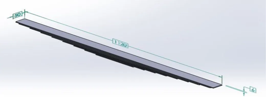
Effective length =1120 mm, ineffective length = 90 mm, no of full length leafs =2 , gradual length leafs = 8, Total leafs =10
length of smallest leaf(leaf 1)= (1120/10-1)+90 = 214 mm length of leaf 2= (1120/10-1)×2+90=338 mm
length of leaf 3= (1120/10-1)×3+90= 463 mm length of leaf 4= (1120/10-1)×4+90=588 mm length of leaf 5 = (1120/10-1)×5+90=712 mm length of leaf 6 = (1120/10-1)×6+90=837 mm length of leaf 7= (1120/10-1)×7+90=961 mm length of leaf 8= (1120/10-1)×8+90=1085 mm length of leaf 9= 1120 mm
length of leaf 10= 1120 mm For steel,
Weight of smallest leaf (leaf 1) = density × volume× acceleration due to gravity = 214 × 6 × 50 × 0.00000786 ×10
= 5.046 N
Weight of leaf 2 = 338 × 6 × 50 × 0.00000786 ×10 =7.97N
Weight of leaf 3 = 463 × 6 × 50 × 0.00000786 × 10 =10.91N
Weight of leaf 4 = 588 × 6 × 50 × 0.00000786 × 10 =13.86N
Weight of leaf 5 = 712 × 6 × 50 × 0.00000786 × 10 = 16.78N
Weight of leaf 6 = 837 × 6 × 50 × 0.00000786 × 10 = 19.73N
Weight of leaf 7 = 961 × 6 × 50 × 0.00000786 × 10 = 22.66N
Weight of leaf 8= 1085 × 6 × 50 × 0.00000786 × 10 = 25.58N
Weight of leaf 9 = 1120 × 6 × 50 × 0.00000786 × 10 =26.40N Weight of leaf10 = 26.40N
Weight of mono leaf spring = 1120 × 24 × 50 × 0.000002 × 10 = 26.88N Weight saved = 175.336 – 26.88 = 148.456N %weight saved = (148.456 ÷ 175.336) × 100
= 84.66%
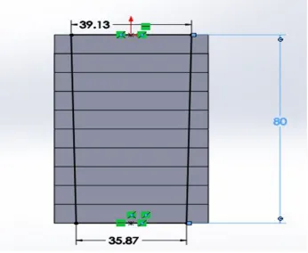
Equalizing the volume of Trapezoidal leaf spring and Rectangular leaf spring Since length of the leaves are same, we can exclude the in both sides. (a+b)/2×h = xy
Where , a = Width of smaller end of trapezoidal leaf Taking h=80 mm b = Width of larger end of trapezoidal leaf Given x=50 mm , y=60 mm h =height
a+b/2×80=50×60 x = width of rectangular leaf
a+b=75 ---① y = thickness of rectangular leaf But b/a=60/55=1.091
b = 1.091×a 2.091a=75 a = 35.868 mm b = 1.091×a b = 39.1319 mm
B. Material for Leaf Spring
The material used for leaf springs is usually a plain carbon steel having 0.90 to 1.0% carbon. The leaves are heat treated after the forming process. The heat treatment of spring steel products has greater strength and therefore greater load capacity, greater range of deflection and better fatigue properties.
1) Carbon/Graphite fibers: Their advantages include high specific strength and modulus, low coefficient of thermal expansion and high fatigue strength. Graphite, when used alone has low impact resistance.Its drawbacks include high cost, low impact resistance and high electrical conductivity.
2) Glass fibers: The main advantage of Glass fiber over others is its low cost. It has high strength, high chemical resistance and good insulating properties. The disadvantages are low elastic modulus poor adhesion to polymers, low fatigue strength and high density, which increase leaf spring weight and size. Also crack detection becomes difficult.
3) Composite materials: A composite material is made by combining two or more materials – often ones that have very different
properties. The two materials work together to give the composite unique properties. However, within the composite you can easily tell the different materials apart as they do not dissolve or blend into each other.
4) Natural composites: Natural composites exist in both animals and plants. Wood is a composite – it is made from long cellulose
fibres (a polymer) held together by a much weaker substance called lignin. Cellulose is also found in cotton, but without the lignin to bind it together it is much weaker. The two weak substances – lignin and cellulose – together form a much stronger one. The bone in your body is also a composite. It is made from a hard but brittle material called hydroxyapatite (which is mainly calcium phosphate) and a soft and flexible material called collagen .
C. Making Composites
Most composites are made of just two materials. One is the matrix or binder. It surrounds and binds together fibres or fragments of the other material, which is called the reinforcement.
D. Composite Leaf Springs
TABLE I
MECHANICAL PROPERTIES OF STEEL
Mechanical Symbols Units Values
Young s Modulus E Gpa 207
Shear Modulus G Gpa 80
Poissons ratio µ .3
Yield strength Sy Mpa 370
Density ρ Kj/m ʒ 7600
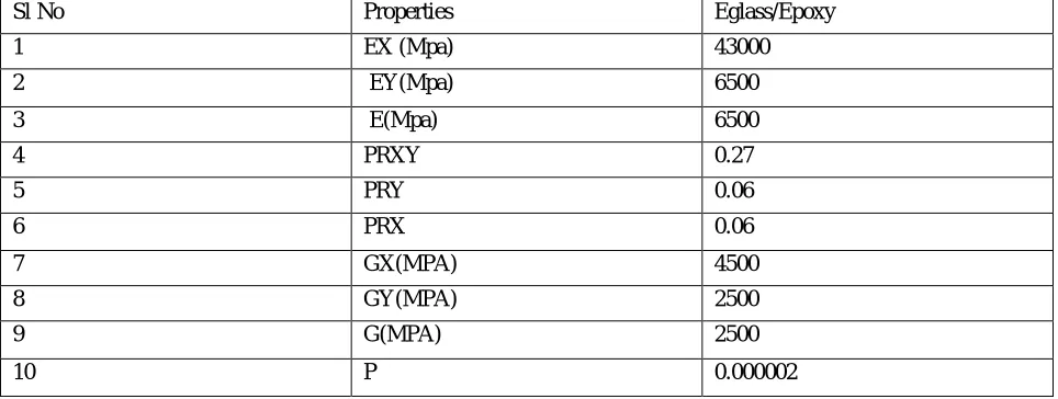
TABLE II
PROPERTIES OF COMPOSITE MATERIALS
Sl No Properties Eglass/Epoxy
1 EX (Mpa) 43000
2 EY(Mpa) 6500
3 E(Mpa) 6500
4 PRXY 0.27
5 PRY 0.06
6 PRX 0.06
7 GX(MPA) 4500
8 GY(MPA) 2500
9 G(MPA) 2500
10 P 0.000002
E. Design
The leaf spring model was done in SOLID WORK software.This work deals with replacement of cross section of rectangular steel leaf spring of a light commercial vehicle with cross section of trapezoidal per leaf & whole shape as a trapezoidal cross section. Numerical calculations are completed with the help of design equations of spring. Dimension of trapezoidal cross section per leaf & trapezoidal cross section are to be taken as same dimension of rectangular cross section of leaf. Different Material had been used for trapezoidal cross section per leaf & trapezoidal cross section & compare with each other .The modeling of the leaf spring have been done in SOLIDWORK. Finite element analysis of the leaf spring have been carried out in ANSYS 16.
TABLE III
LEAF SPRING PARAMETERS
Leaf No: Full leaf length (mm) Radius of curvature
1 1120 961
2 1120 967
3 1085 973
4 961 979
5 837 985
6 712 991
7 588 997
8 463 1003
9 338 1009
[image:5.612.61.550.566.730.2]1) Sketching: To create a line in a 3D sketch:
a) Click 3D Sketch (Sketch toolbar) or Insert > 3D Sketch.
i) In new parts, the view changes to Isometric.
b) Click Line (Sketch toolbar) or Tools > Sketch Entities > Line.
c) In the PropertyManager, under Options, select one of the following:
i) For construction to create a 3D construction line.
ii) Infinite length to create a 3D line of infinite length.
iii) Midpoint line to create a line that is symmetrical from the midpoint of the line.
d) Click in the graphics area to start the line.
i) The 3D Line PropertyManager appears and the pointer changes to .
ii) Each time you click, the space handle appears to orient your sketch.
iii) If you want to change planes, press Tab.
iv) Drag to where you want the line segment to end.
v) To continue the line, select the end point and press Tab to change to another plane if necessary.
[image:6.612.108.506.304.477.2]vi) Drag the second segment and release the pointer.
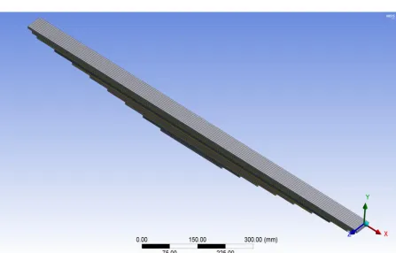
Figure 1. Assembled model of leafspring developed in solidwork
[image:6.612.49.569.513.703.2]
Figure 3. TrapeZoidal cross section
By using 60/55 cross section its found that, value of stress & displacement is nearer to rectangular cross section . It also found from result that as value of width increased its result in decreasing value of stress & deflection. So proper cross section for leaf spring is selected 60/55.
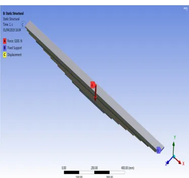
F. Analysis
The analysis is done in ANSYS 16.0, the analysis is the limitation of the operation of practical conditions, The boundary conditions and loading conditions are entered in the ansys platform. From the Finite element analysis the normal and shear stress of each points under the different loading conditions are obtained.The software implements equations that govern the behaviour of these elements and solves them all; creating a comprehensive explanation of how the system acts as a whole. These results then can be presented in tabulated, or graphical forms. This type of analysis is typically used for the design and optimization of a system far too complex to analyze by hand.This enables a reduction in the level of risk, and in the cost of ineffective designs. The multifaceted nature of ANSYS also provides a means to ensure that users are able to see the effect of a design on the whole behaviour of the product.
1) Process In Ansys:
a) Build Geometry: Construct a two or three dimensional representation of the object to be modeled and tested using the work
plane coordinate system within ANSYS.
b) Define Material Properties: Now that the part exists, define a library of the necessary materials that compose the object(or project) being modeled. This includes thermal and mechanical properties.
c) Generate Mesh: At this point ANSYS understands the makeup of the part. Now define how the modeled system should be
broken down into finite pieces.
d) Apply Loads: Once the system is fully designed, the last task is to burden the system with constraints, such as physical loadings or boundary conditions.
e) Obtain Solution: This is actually a step, because ANSYS needs to understand within what state (steady state, transient… etc.) the problem must be solved.
f) Present the Results: After the solution has been obtained, there are many ways to present ANSYS’ results, choose from many
2) Static Analysis: Used to determine displacements, stresses, etc. under static loading conditions. ANSYS can compute both linear and nonlinear static analyses. Nonlinearities can include plasticity, stress stiffening, large deflection, large strain, hyper elasticity, contact surfaces, and creep.
Figure 4. Leaf spring modelled in Ansys
[image:8.612.119.492.366.716.2]Figure 6. Displacement boundary conditions
[image:9.612.83.530.424.710.2]IV. RESULTANDDISCUSSION
[image:10.612.151.475.114.381.2]A. Analysis Results 1) For Steel
Figure 8. Deformation on steel Values of Deformation
Maximum: 0.0004301m
Figure 9. Equivalent stress Values of Equivalent stress
[image:10.612.138.474.437.670.2]3) For E-Glass Epoxy
Figure 10. Deformation on E-GLASS EPOXY
Value of Deformation on E-GLASS EPOXY Maximum: 0.0023004m
Figure 11. Equivalent stress Value of Equivalent Stress
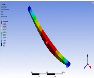
[image:11.612.102.514.401.687.2]Figure 12. Deformation on trapezodial shape [E-GLASS EPOXY]
Value of deformation on trapezoidal shape Maximum 0.00013804m
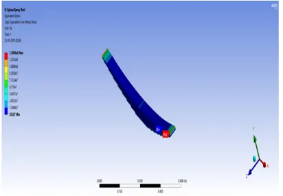
Figure 13 Equivalent stress
Value of Equivalent stress
[image:12.612.86.540.421.668.2]TABLE4.
RESULTANALYSIS
Cases Deformation (m) Equivalent Stress (Pa)
Conventional steel leaf spring 0.0004301 1.6757×10⁸
E-glass/Epoxy leaf spring 0.0023004 1.3896×10⁸
E-glass/Epoxy leaf spring of
trapezoidal shape
0.0013804 1.0391×10⁸
V. CONCLUSION
A. From static analysis results, it is seen that maximum von misses stress for a given load of 3200N for steel leaf spring of rectangular cross section is 1.6757×10⁸ Mpa and maximum deformation is .0004301m.
B. From static analysis it’s found that by using E-glass/Epoxy for a given load of 3200N on rectangular cross section leaf , maximum von mises stress is 1.3896×10⁸ Pa and maximum deflection is 0.0023004m.
C. From static analysis it’s found that by using E-glass/Epoxy for a given load of 3200N on trapezoidal cross section maximum
von mises stress is 1.0391×10⁸ Pa and maximum deflection is 0.0013804mm.
D. All the FEA results are compared with the theoretical results and it is found that they are within the allowable limits and nearly equal to the theoretical results.
E. From static analysis it is observed that by using trapezoidal cross- section leaf spring are better when compared with rectangular cross-sectional leaf spring.
VI. ACKNOWLEDGMENT
Presentation, inspiration and motivation have always played a key role in the success of any venture. First of all we would like to thank God, the almighty for his kind blessings upon us for the completion of this project work.We express our sincere thanks to all the faculty members of mechanical engineering department for their valuable guidance and kind supervision.We surrender our esteemed and sincere thanks to all the faculty members of mechanical engineering department for their help and timely suggestion. We are thankful to our parents and friends for their motivation and support.
REFERENCES
[1] Syambabu Nutalapati, Design And Analysis Of Leaf Spring By Using Composite Material For Light Vehicles , Ijmet_06_12_005 , Volume 6, Issue 12 , Pp. 36-59,Dec 2015
[2] Rohit Gosh And Susvosh, Static Analysis Of Multileaf Spring Using Ansys Benchmark 16,Ijmet_07_05_025 Volume 7,Issue 5,Pp.241-249 , September-October 2016
[3] Kabariya Kaushal Kanubhaii, Shyam Gupta,,Design And Analysis Of Automobile Leaf Spring By Changing Cross Sectional Area And Compared It With Composite Material,Ijariie-Issn(O)-2395-4396,Vol-4, Issue-1
![Figure 12. Deformation on trapezodial shape [E-GLASS EPOXY]](https://thumb-us.123doks.com/thumbv2/123dok_us/1242748.650407/12.612.86.540.421.668/figure-deformation-trapezodial-shape-e-glass-epoxy.webp)