Current Transducer
GRID AC
DC
Controller
A Review on Integration of PV to the Grid using
Current Control Techniques
Ankur Sharma, Imran Khan
1
M.TECH Scholar, 2Associate Professor, Azad Institute of Engineering and Technology, lucknow
Abstract: This review deals with the increasingly urgent energy issues, the world attaches great importance to begin the development of n ew energy and related technology. At present, large scale photovoltaic power generation and scale of renewable energy has become parts of development strategy, meanwhile it is the way to guide the development of photovoltaic industry. However, because of its own characteristics different from conventional power generation grid connected PV power station and its security, stability, reliable operation become new challenges which power grid and PV power plant need to face. Grid connected voltage source inverters are essential for the integration of the distributed energy resources. However, due to the small capacity and intermittent nature of the renewable sources, it is extremely difficult to integrate them in the existing grid system. The concerns of instability and unpredictability have kept the renewable sources away from participating in real time power generation.
I. INTRODUCTION
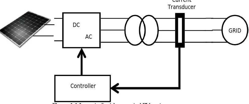
[image:1.612.126.532.459.630.2]Modern power systems, observing to the Smart Grid concept, involve more and more the integration of the Distributed Energy Resources (DER) mainly based on clean energy sources like solar and wind power. The integration of these renewable resources to the utility grid becomes essential to increase the reliability and the ability of power systems. In this sense, the greenhouse emissions can be seriously reduced. Voltage source inverters are power electronics circuits widely used to line the distributed energy resources with the advantage power system. Grid connected VSIs are normally operated by controlling its output power, two possible control schemes can be applied either voltage or current control. The phase angle and amplitude of the output voltage are controlled according to the desired output power by voltage control. For the current control, the current injected by the inverter is directly controlled to produce the desired output power.
Figure 1.1 Layout of grid connected PV system
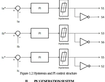
Hysteresis Current Control (HCC) was initially applied as an analog controller and it is frequently used for grid connected inverters configuration reflecting its fast transient response, good accuracy, implementation simplicity and fundamentally over-current protection. Common Hysteresis Current Control has two main disadvantages, the variable switching frequency depending on the
Figure 1.2 Hysteresis and PI control structure
II. PV GENERATION SYSTEM
Grid connected PV generation system is generally composed of the PV array, the inverter device with the purpose of extreme power tracking and the control system. Photovoltaic system use solar panels to alter sunlight into electricity. A structure is made up of one or more solar PV panels or dc power converter that holds the solar panels, and the interconnections and accumulating for the other components. Photo-voltaic (PV) is the name of a method of altering solar energy into direct current electricity using semiconducting materials that exhibit the photovoltaic effect
A. PV Modules or Solar Panels
Due to low voltage of the single solar cell (mainly 0.5v) several cells are wired in series for construction of a shield. Then the shield is assembled into a protective weather proof enclosure thus making a PV module or solar panel. Modules are then threaded together into a PV array.
A photovoltaic array is a connected assembly of PV modules. Most PV array use an inverter to alter the dc power produced by the modules into AC. The modules in a PV array are connected in series to obtain the desired the voltage, the single string are then connected in parallel to allow the system to create more current.
A solar or PV inverter alters variable direct current (DC) output of the photovoltaic solar panel into a utility frequency AC that can be consumed into a commercial electrical grid or it is used by the native or off grid electrical network. It is a critical component in the PV system allowing the use of ordinary commercial applications. Solar inverters have special functions adapted for use with the photovoltaic arrays including maximum power point tracking and anti-islanding protection.
B. Characteristics of Solar Array
A photovoltaic system uses one or more solar modules or solar panels to convert solar energy to electrical energy. Basically its include solar panels, electrical, mechanical connections and means of modifying the electrical output.
Figure 2.1 Basic PV cell structure
2) Photovoltaic Array: Again the power produced by a single photovoltaic module is not sufficient to meet the power demands for most of the practical purposes. PV array can use inverters to convert the dc output into ac and use it for motors, lighting and other loads. The modules are associated in series for more voltage rating and then in parallel to meet the current descriptions.
C. Working Of PV Cell
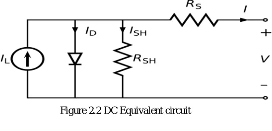
The PV cell is based on the principle of photoelectric effect. Photoelectric effect can be defined as when an electron gets ejected from the conduction band as a consequence of absorption of the sunlight of certain wavelength by the matter. So, in a photovoltaic cell when sunlight attacks its surface, some portion of the solar energy is absorbed in the semiconductor material. If absorbed energy is greater than the band gap energy of the semiconductor, the electrons from the valence band jumps to the conduction band. By this, pair of hole electrons are created in the irradiated region of the semiconductor. The electrons generated in the conduction band are now able to move. These free electrons are enforced to move in a particular direction by the act of electric field present in the PV cell. This electron establishes current and can be drawn for exterior use by connecting a metal plate on top and bottom of PV cell. This current and voltage created because of its built in electric fields produces required power.
Figure 2.2 DC Equivalent circuit
III. CURRENT CONTROL TECHNIQUES
Among multiple functions of grid connected systems, the current control plays one of the most important roles. The performance of the complete system largely depends on the quality of the applied current control strategy. It has to fulfill basic requirements, such as low harmonic distortion of the output current, high dynamic response, regulation of the dc-link voltage and, in a number of cases, provide bi- directional power flow. The desire to propose a current control strategy which combines most of these requirements has encouraged many researches in the last two decades. A large number of current controller techniques have been described for different applications, namely ac drives, active filters, uninterruptible power supplies, ac-dc converters, etc. These control strategies achieve the same basic steady-state goal of controlling the fundamental input or output current waveform; however they differ on the implementation complexity, dynamic response and output current harmonic contents. Although the existing current control techniques vary from very simple hysteresis methods to complex analytical approaches, they are all based on the same basic principle. The load current is controlled by correctly modulating the converter input/output voltage.
One of the earliest introduced current control approaches based on this comparison technique is the ramp-comparison controller. It compares the control signal generated according to the current error to a triangular carrier waveform, to generate the switching states. The main advantage of this concept is that the inverter operates at a fixed switching frequency defined by the frequency of the triangular carrier waveform. However, the system response is affected by stability requirements of the feedback loop, which also depends to load parameters. Moreover, it performs an inherent phase and amplitude error even in steady-state operation.
[image:3.612.180.454.376.508.2]particular interest. Moreover, new generations of microcontrollers and digital signal processors are released with highe processing capability and with additional number of peripheries. This trend has boosted the utilization of control schemes that demand complex on-line processing and stored elements. The Direct Power Control concept fits into these characteristics, since it requires an instantaneous calculation of the active and reactive powers that are compared to the desired references. The error signals are used to select from a stored switching table the optimum switching state. Another approach which is increasing force with the development of faster DSP devices is the predictive control. It calculates the optimum inverter voltage required to drive the actual currents according to the reference values. Although it gives optimum performance in terms of both response time and accuracy, it takes more calculations and requires a good knowledge of the load parameters. The dependency of load parameters is eliminated for the hysteresis control approach which uses hysteresis comparators to select the proper switching states based on the comparison of the current error with switching boundaries defining a hysteresis band. Although simple and extremely robust, this control technique exhibits several unsatisfactory features such as varying modulation frequency over a fundamental period. A good performance concerning steady-state accuracy is obtained using synchronous reference frame transformation. Using rotating dq-reference frame theory, ac values become dc quantities and can be easily regulated using PI controllers. However, stability and dynamic performance are again influenced by load parameters.
Each of the existing current control techniques has its own characteristics and strengths, which makes it suitable for specific applications. Furthermore, properties associated to switching frequency, load current distortion and dynamic behavior usually contradict each other. Therefore, the choice of the most appropriate current control method means searching for the best compromise between these characteristics and the nature of the application.
A. Ramp-Comparison Control
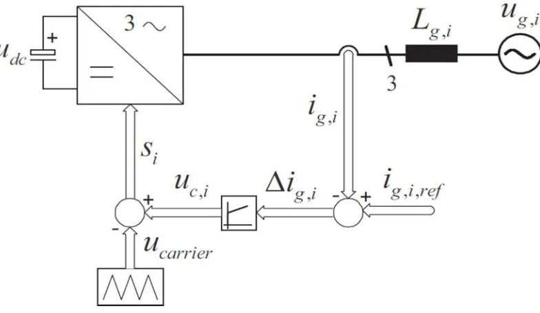
[image:4.612.117.509.387.614.2]The ramp-comparison current controller uses proportional-integral (PI) error compensators and a fixed frequency triangular carrier to generate the gate signals of the converter power switches. Based on the phase current error (∆Ig,i) the PI controller derives the modulating signals (Uc,i) to be compared to the pulse-width modulator (triangular carrier) as shown in Figure 3.1
Figure 3.1: Ramp-comparison current control scheme
Figure 3.2 illustrates the inverter output voltage resulting for the comparison between the control signal Uc,i and the triangular carrier Ucarrier. If the control signal is higher than the triangular waveform, the witches are activated to apply Udc to the output. On the other hand, if the control signal is lower than the triangular carrier, an output voltage equal to −Udc is produced.
Figure3.2 Inverter output voltage
Additionally, the points of intersection define the switching instants of the power switches. This maintains the switching frequency constant, since the triangular carrier is operated with a fixed frequency. However, despite this main advantage, the control concept has inherent amplitude and phase tracking error, as the PI controller has to process AC signals. Furthermore, it can be affected by stability requirement of the current feedback loop which is highly dependent to load parameters.
B. Voltage-Oriented Control
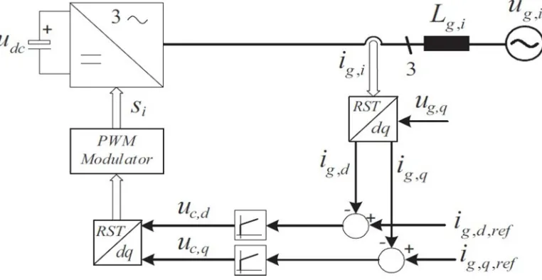
Voltage-Oriented Control (VOC) scheme uses the rotating dq frame theory to ensure a zero steady-state output current error. By transforming ac phase quantities to dc components, the infinite dc gain of the PI controllers is able to lead actual dq currents to the desired values without introducing static errors.
[image:5.612.115.496.523.720.2]In the particular case of the VOC scheme the synchronous transformation is oriented such that the d-axis is aligned to the grid voltage vector. The load current vector ig, is divided into rectangular components, where the component ig,d determines the active power whereas ig,q controls the reactive power flow.
Figure 3.9 illustrates the VOC principle involving the use of rotating synchronous rectangular coordinates. The three measured output phase currents are converted to dq components using synchronous reference frame transformation and compared to the respective reference values (ig,dq,ref ). Two PI regulators compensate any existing error by generating appropriate control voltages uc,d and uc,q, which are transformed back to phase quantities and used as inputs by the pulse-width modulation (PWM) block to generate the command signals to the power devices. Although, the described approach allows efficient regulation of active and reactive power flow using two distinct loops (ig,d and ig,q), the control of these variables are not performed completely independent.
C. Direct Power Control
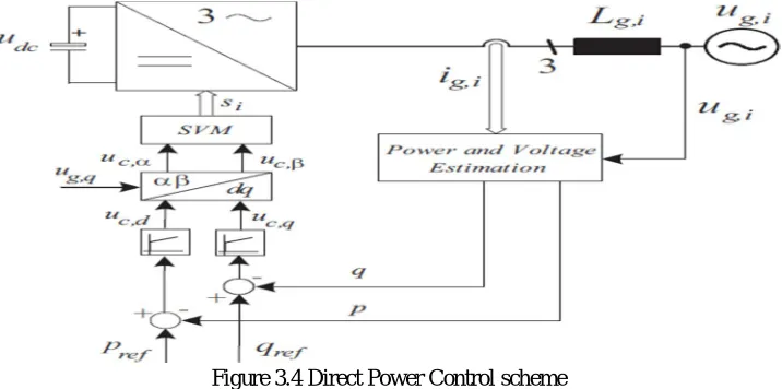
[image:6.612.128.486.234.412.2]The Direct Power Control (DPC) concept proposed by Noguchi et. Al slightly differs from the other current control techniques which use inner current control loops to directly regulate the load currents. Instead of that, DPC (Figure 3.4) regulates instantaneous phase currents in terms of active and reactive powers.
Figure 3.4 Direct Power Control scheme
It is based on the industry standard practice for ac machines known as Direct Torque Control (DTC). For the DPC approach active and reactive power variables are directly controlled in a manner analogous to torque and flux control in motor drives applications. The three-phase currents and grid voltages are used to estimate the instantaneous active and reactive powers that are compared to respective references. Usually, the active power reference Pref is set by the dc-link voltage controller and the reactive power reference Qref is adjusted to zero to ensure unit power factor. Two hysteresis controllers based on p and q error quantities and a grid voltage position detector supply the inputs to the switching table which is in charge to select the optimum voltage space vector of the converter. The influence of each vector on the instantaneous real and imaginary powers is diverse and results in different control dynamics. The impact of each vector is analyzed off-line and properly stored in a switching table according to the operating condition.
One of the most important aspects on DPC apart from the switching table is the correct estimation of the active and reactive powers. It can be performed either based on three- phase quantities.
D. Predictive Current Control
Due to the availability and continuous development of powerful and fast microprocessors, the interest in current control techniques which demand high computational effort is increasing. The performance of this type of controllers is rising proportionally to the speed and calculation power of new families of microprocessors. The basic idea of the predictive current controller is to perform a fast and accurate control loop that selects the optimum control action among all possibilities, to fulfill a certain predefined criteria. This decision is based on the knowledge of actual variable measurements and load parameters.
Figure 3.5 Basic structure of the Predictive current control approach
E. Hysteresis Control
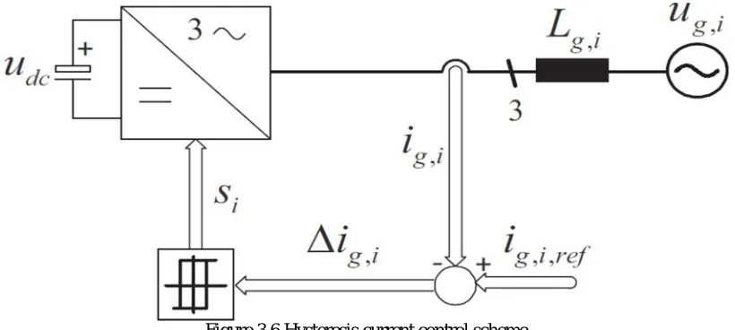
The basic concept of the hysteresis current control is to switch the output voltage level (+udc to −udc for a two-level system) appropriately whenever the measured current goes above or below a given tolerance boundary. The current errors resulting from the comparison between measured currents and respective phase current references are controlled using three independent hysteresis comparators as illustrated in Figure 3.6 by the simplified diagram of a typical three-phase hysteresis current controller.
Figure 3.6 Hysteresis current control scheme
[image:7.612.102.512.360.544.2]This variable switching frequency results in an undesirable spread of the ripple current harmonics, which complicate the design of the output filter and may generate unwanted resonances on the utility grid. Another important factor which influences the switching frequency is the interference between the commutations of the three phases, inherent to three-phase system without a neutral connection. In this case, each phase current not only depends on the corresponding phase voltage but it is also affected by the voltage of the other two phases. Furthermore, due to this interaction between the phases the instantaneous current error is not limited within the tolerance band, but it can reach double of this value. If the output voltage of one phase should be reversed in order to maintain the current error within the given tolerance band, this transition can be made impossible by the switching state of the other two phase controllers. Therefore, the current error continues to increase until it reaches twice the band width where a switching action is enforced in another phase according to iR + iS + iT = 0
However, although the inclusion of new concepts into the classical hysteresis control increases the level of complexity, they do not affect dynamic response and stability issues. Therefore, constant switching frequency hysteresis control emerges as a well suited approach for high performance high-speed applications.
As described above, there is no control technique which is able to fulfill all requirements in terms of stability, harmonic content, dynamic response and simplicity. These specifications usually contradict each other, demanding a careful analysis of the compromise between these characteristics and the nature of the application. Besides the characteristics there exist some additional attributes that must be take into account for the selection of the control technique. The ramp-comparison for example, has an inherent amplitude and phase tracking error which limits its applications in the majority of the cases. For grid connected systems, the direct power control is a practical alternative, since it provides a direct control of the active and reactive powers without any current control loop. Moreover, it turns to be robust to possible variations of the grid impedance. Hysteresis current controller has a well-defined harmonic spectrum, robust, extremely fast and is very simple to implement.
IV. CONCLUSION
This paper has reviewed how to design a control method for three- phase grid- connected inverter system for distributed generation application. The method is hysteresis current control along with PI control for grid connected voltage source inverter. This work discusses methods for controlling the flow of energy between renewable energy sources and the utility network. The emerging interest in such technologies demands continuous research of new control concepts, especially in the area of high voltage and high power applications. For the future research, the following improvement can be implemented.
REFERENCES
[1] F. Blaabjerg, R. Teodorescu, Z Chen, and M. Liserre, “Power Converters and Control of Renewable Energy Systems”, in Proceeding of International Conference on Power Electronics (ICPE’04), 2004.
[2] Lai Jih-Sheng and Peng Fang Zheng, “Multilevel Converters-A new Breed of Power Converters”, IEEE Transactions on Industry Applications, vol. 32, no. 3, pp. 509–517, 1996.\
[3] N. S. Choi, J. G. Cho, and G. H. Cho, “A General Circuit Topology of Multilevel Inverter”, in Proceeding of Power Electronics Specialists Conference (PESC ’91), 1991, pp. 96–103.
[4] H. Habeebullah Sait, S. Arul Daniel, “New control paradigm for integration of photovoltaic energy sources with utility network” Electrical Power and Energy Systems 33 (2011) 86–93
[5] M. Marchesoni, “High-Performance Current Control Techniques for Application to Multilevel High-power Voltage Source Inverters”, IEEE Transactions on Power Electronics, vol. 7, no. 1, pp. 189–204, 1992.
[6] Zargari NR, Ziogas, Joos G. A two switch high performance current regulated DC/AC converter module. In: Proceedings of IEEE industry application social annual meeting, vol. 2; 1990. p. 929–34.
[7] S. D. Round, L. Dalessandro, and J. W. Kolar, “Novel Phase Decoupling and Coordinating Tolerance Band Current Control for Three-Phase Three-Level PWM Rectifiers”, in Proceeding of European Conference on Power Electronics, Drives and Motion (PCIM’2005), Nuremberg, Germany, 2005, pp. 285–291. [8] B. K. Bose, “An Adaptive Hysteresis-Band Current Control Technique of a Voltage-Fed PWM Inverter for Machine Drive System”, IEEE Transactions on
Industrial Electronics, vol. 37, no. 5, pp402–408, 1990.
[9] G. Marcelo, J. Gazoli and E. Filho, “Comprehensive Approach to modeling and Simulation of Photovoltaic Arrays”, IEEE Trans. Power Electron. Vol. 24, no. 5, pp.1198-1208, May 2009.
[10] Pooya Ghani , Vahid Asadzadeh “Implementation of Three-phase grid-connected inverter Using TMS320LF2407A microprocessor”, Power Electronics, Drive Systems and Technologies Conference (PEDSTC), 2011 2nd DOI: 10.1109/PEDSTC.2011.5742437 Publication Year: 2011 , Page(s): 305 – 310 Cited by: Papers (2)
[11] Jaime Castelló Moreno, José M. Espí Huerta, Rafael García Gil and Sergio AlejandroGonzález, “ Robust Predictive Current Control for Three-Phase Grid- Connected Inverters”. IEEE Transactions on Industrial Electronics, vol. 56, no. 6, June 2009.